Stephan ARTEC Series User manual
1
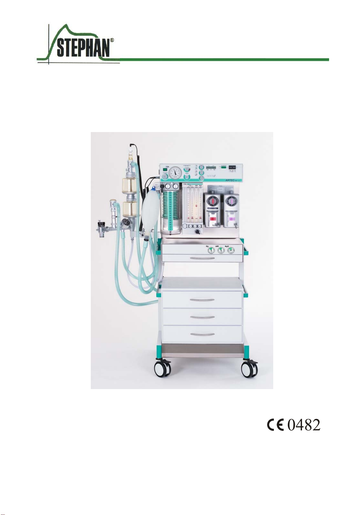
ARTEC
Anesthesia system
Version 1.2. Status 04.10/
Picture shows Artec with optional components
Operating instruction


3
Table of contents
1GENERAL INFORMATION 5
2TECHNICAL DESCRIPTION 6
2.1 Possible Expansion and Upgrading of the Unit 6
2.2 Scope of Use and Application 8
3DESCRIPTION 9
3.1 Gasmixing unit 3 and 4 9
3.2 O2– Ratiosystem (optional) 10
3.3 O2-Flush 11
3.4 AIR/N2O Mode Switch 11
3.5 O2- supply deficiency signal 11
3.6 Nitrous Oxide Block 11
3.7 Vaporizer 12
3.8 Gas-cylinder Supply Component 13
4CHANGEOVER MOUNTING ARM (OPTIONAL) 14
4.1 Top view 14
4.2 Front view 15
4.3 Rear view 16
4.4 Connecting the changeover mounting arm 17
5TESTING UNIT FUNCTIONS 21
5.1 Dosage valves of the Gas Mix Unit 21
5.2 O2-Flush 21
5.3 AIR / N2O Mode Switch 21

Operating Instructions Artec
4
6GAS TYPE TEST AND TESTING SAFETY DEVICES 23
6.1 Testing Gas Type: 23
6.3 Testing the Vaporizer / Vaporizer holding rack 24
7CLEANING AND CARE OF ANESTHESIA UNIT 25
8TROUBLESHOOTING 26
8.1 ARTEC 26
8.2 Changeover mounting arm (if available) 27
9TECHNICAL DATA 29
10 MAINTENANCE AND SERVICING 31
10.1 Artec 31
10.2 Changeover mounting arm (if available) 31

Operating Instructions Artec
5
1 General Information
The Medical Equipment Regulations (MedGV), and the law on technical medical working
materials (MPBetreibV) stipulate that the attention of the operator must be drawn to the
following:
The operation of the Unit must be carried out only by qualified personnel. Exact knowledge
and understanding of the Operating Instructions is a pre-conditioned for operation.
Use of the equipment is solely for that as stipulated in the Operating Instructions.
Inspections and servicing must be duly entered in the Logbook of the Unit. The Equipment
must be inspected at regular intervals by qualified personnel only.
F.Stephan GmbH stipulates a half-yearly inspection and maintenance by one of its
authorized Service Technicians.
Before each use of the unit, a complete function test of the unit must be carried out.
In the case on medico.technical devices with electrical connection, the standards of
particular VDE 0751 and IEC 601 must be closely complied with. According to these
standards, such devices may only be set up and put into operation by the manufacturer or
his expressedly authorized technician or dealership.
Unit equipped with a pressure reducer should undergo a basic overhaul at least every 5
years for reasons of safety.
An emergency ventilation system (e.g. Ambu-Bag) must always be in close proximity of
the unit.
F. Stephan shall assume no responsibility or liability for any damage or defects arising
from non-observance of the above-mentioned information.
Table of contents
Other Stephan Medical Equipment manuals


Popular Medical Equipment manuals by other brands


Getinge
Getinge Arjohuntleigh Nimbus 3 Professional Instructions for use

Mettler Electronics
Mettler Electronics Sonicator 730 Maintenance manual

Pressalit Care
Pressalit Care R1100 Mounting instruction

Denas MS
Denas MS DENAS-T operating manual

bort medical
bort medical ActiveColor quick guide

AccuVein
AccuVein AV400 user manual


