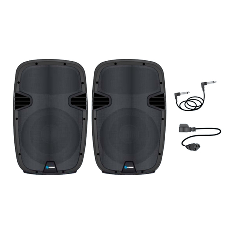
Steren BAF-510 User manual


Before using your new Portable 150W PA System, please
read this instruction manual to prevent any damage. Put it
away in a safe place for future references.
FEATURES
Convenient portable PA package with luggage-style handle
and wheels for easy transport
5-channel 150W RMS powered mixer
Stereo two-way speaker system with 10” woofer and
piezoelectric tweeter horn, speaker cables, two folding
speaker stands
XLR and1/4” mic/line inputs
Stereo source inputs for CD, VCR or DVD or other audio
sources
Bass, treble and reverb controls
DSP
Five-band graphic equalizer
Dynamic microphone
Storage compartment for microphones, cables and
accessories
Stereo RCA auxiliary outputs
WARNING
An equilateral triangle enclosing a lightening
flash / arrowhead symbol is intended to alert the
user to the presence of uninsulated dangerous
voltage within the product’s enclosure which
may be of sufficient magnitude to constitute a
risk of electric shock.
An equilateral triangle enclosing an exclamation
point is intended to alert the user to the
presence of important operating and service
instructions in the literature enclosed with this
unit.
•
•
•
•
•
•
•
•
•
•
•
ENGLISH
ENGLISH-2
Before usin
g
y
our new Portable 150W PA S
y
stem, please
read this instruction manual to prevent an
y
dama
g
e. Put it
a
wa
y
in a safe place for future references
.

IMPORTANT SAFETY INSTRUCTIONS
When using this electronic device, basic precautions should
always be taken, including the following:
Do not use this product near water (e.g. near a bathtub,
washbowl, kitchen sink, swimming pool, etc.).
This product, in combination with headphones or speakers,
may be capable of producing sound levels that could cause
permanent hearing loss. Do not operate for a long period of
time at a high volume level or at a level that is
uncomfortable. If you experience any hearing loss or ringing
in the ears, you should consult a doctor.
The product should be positioned so that proper ventilation
is maintained.
The product should be located away from heat sources such
as radiators, heal vents, or other devices (including
amplifiers) that produce heat.
This product should be used only with a cart or stand that will
keep it level and stable and prevent wobbling.
The product should be connected to a power supply only of
the type described in the user’s manual or as marked on the
product. Replace the fuse only with one of the specified type,
size and correct rating.
The power cord should: 1) be undamaged, 2) never share
an outlet or extension cord with other devices so that the
outlet’s or extension cord’s power rating is exceeded, and 3)
never be left plugged into the outlet when not being used for
a long period of time.
Care should be taken so that objects do not fall into, and
liquids are not spilled through, the enclosure’s openings.
This product should be serviced by qualified personnel if:
- The power cord or the plug has been damaged
- Objects have fallen into, or liquid has been spilled onto
the product
•
•
•
•
•
•
•
•
•
ENGLISH
ENGLISH-3
- The product has been exposed to rain
- The product does not appear to operate normally or
exhibits a marked change in performance
- The product has been dropped, or the enclosure
damaged
Do not attempt to service the product beyond what is
described in the user maintenance instructions, All other
servicing should be referred to qualified service personnel.
INSTALLATION
1. Inspection
Your new Portable Sound System was carefully packed at the
factory in packaging designed to protect the units in shipment.
Before installing and using your unit, carefully examine the
packaging and all contents for any signs of physical damage that
may have occurred in transit.
CONTENTS
Mixer
2 speakers
2 stands
1 microphone
Cable for speakers and microphone
Power cord
Instruction manual
2. Setup
After transporting the device to the desired location, lay the unit
down on its flat side. Unclasp the side panel latches by pulling up
on the yellow tab to release and unhook the latch. Carefully lift
off the speakers and then remove the speaker stands and
accessories from inside the unit.
Mixer
Position the mixer in a flat surface. Parts of the unit can become
very warm during use. This is normal during operation. Care
should be taken to ensure that there is enough space behind the
Mixer for cooling. Also, do not place the Portable Sound System
on high temperature devices such as power amplifiers, etc., or
the unit may overheat in operation.
•
•
•
•
•
•
•
•
ENGLISH
ENGLISH-4

Please make sure that the power unit supplied is marked for the
correct voltage in your area. Power requirements for electrical
equipment differ from area to area. It is wise to confirm the
voltage and use the appropriate power supply unit before
connecting it to power sources.
Speakers and Stands
Fully extend the speaker stand tripod legs and tighten the base
thumbscrew. Extend the pole of the stand to the desired height
and insert the safety pin completely through the stand hole
above the pole thumbscrew. Lower the pole so that the pin rests
on the holder and tighten the pole thumbscrew.
Setup the stands on a flat surface where the speakers will be
located and not disturbed. Place the speakers on the stands and
position them as desired.
Facing the speakers towards any of the microphones connected
with the mixer will increase the chance of feedback.
Connect the speaker cables to the input jacks on the lower left
front panel of both the Left and Right speakers.
Connect the other end of each cable to the corresponding Left
and Right speaker outputs on the rear panel of the mixer.
Position the length of the cables so they will not be a safety
hazard to people.
Connect only the supplied speakers to the mixer.
Inputs
Connect all sound sources to the appropriate inputs i.e.,
microphones, keyboards, CD players, karaoke machines. The
supplied microphone is ideal for vocal.
When ready to operate, plug the AC cord into the power source.
Make sure that the unit is turned off before connecting to the AC
power source to avoid possible loud transients which can dam-
age your speakers or your ears. Before turning on, connect up
the speakers and all inputs and outputs desired and turn down
the Master Volume.
ENGLISH
ENGLISH-5
C
onnect onl
y
the supplied speakers to the mixer.

CONTROLS
1.- CHANNEL 1-3 XLR INPUT
The XLR mic inputs are an electronically balanced XLR type
designed to accept mic level signals from any balanced low
impedance microphone.
2.- CHANNEL 4 XLR & 1/4” STEREO/MONO INPUTS
The XLR input is balanced, designed to accept mic level signals.
The Left and Right 1/4” line inputs are unbalanced and are
designed for connecting stereo line level audio signals or only
the Left/Mono jack can be used for connecting mono signals.
The XLR input is defeated when either of the 1/4” inputs are
used.
3.- CHANNEL 5 STEREO RCA INPUTS
The stereo RCA line level inputs can be used for connecting CD
players, Tape Decks, and other audio equipment with line level
outputs.
4.- MONO / STEREO MODE
When the Mono/Stereo button is out (stereo mode) the Left
RCA Aux In is sent to the Left Speaker and Right RCA Aux In is
sent to the Right Speaker. When the button is depressed (Mono
mode), both L and R RCA input signals are mixed and sent to
both speakers.
1234
14
8910 11
12
13
15
5
6
7
ENGLISH
ENGLISH-6

5.- REVERB
This control allows you to set the reverb effect level sent to the
speakers.
6.- TREBLE CONTROL
Turn to the right to boost high frequencies, adding crispness too
percussion from drum machines, cymbals and synths. Turn to
the left to cut these frequencies, reducing sibilance or hiss. The
control has a shelving response giving +/-10dB of boost or cut at
10kHz.
7.- BASS CONTROL
The bass control shelving response gives 10dB of boost or cut
at 100Hz. Add warmth to vocals or extra punch to guitars, drums
and synths by turning to the right. Turn to the left to reduce stage
rumble, hum or to improve a mushy sound.
8.- GAIN
Allows you to set the volume level per channel
9.- DSP EFFECTS DISPLAY
Displays the selected effect out of 16 possible effect presets.
10.- DSP EFFECTS SELECTOR
The UP/DOWN buttons allow fast and easy scrolling in either
direction through the 16 effect presets.
Effects List:
Half 1, Half 2, Room 1, Room 2, Room 3, Plate 1, Plate 2, Plate
3, Chorus, Flange, Delay 1, Delay 2, Chorus/Room, Chorus/
Room 2, Vocal cancel, Rotary speaker.
11.- POWER ON INDICATOR
This LED lights blue when the unit is ON.
12.- 5-BAND GRAPHIC EQ
The 5-band channel graphic equalizer allows you to adjust the
frequency response of the L and R Channel bus signal, providing
a maximum of ±12dB of cut and boost for each frequency band
from the flat position.
ENGLISH
ENGLISH-7

13.- INDICATORS
These LED indicators will light red when there is a high level
audio signal at the indicated frequency. These can be used to
detect an audio feedback frequency and then lower the
appropriate EQ fader to remove the unwanted feedback.
14.- AUX RCA OUTPUTS
The Left and Right RCA outputs provide line level signal
output to a cassette deck, home audio equipment, or a recording
device.
15.- L/MONITOR and R/MAIN MASTER VOLUME
These control the final level of the signal sent to the left and right
speaker outputs and the aux RCA outputs.
16.- FUSE HOLDER & POWER CORD CONNECTOR
The cord connector is used to connect the AC power source to
your power amplifier.
This fuse holder contains an AC primary fuse. When this fuse
blows, replace it with the same type fuse, size and power rating.
If it continuously blows, stop replacing the fuse and refer
servicing to qualified personnel.
17.- AC VOLTAGE SELECT SWITCH
Before plugging in the power cord, check to see that the unit is
set for the proper voltage for your area.
16
17
18 19
ENGLISH
ENGLISH-8

18.- POWER SWITCH
Use this switch to power unit ON or OFF. Before turning on this
unit, verify connection to the proper voltage AC source, check all
connections and turn down the level controls of equipment
connected to the outputs.
19.- SPEAKER 1/4” OUTPUT JACKS
Connect to the left and right speakers.
SPECIFICATIONS
Input: 120/240V ~ 50-60Hz 150W
Frequency response.: 20Hz – 20kHz < 1dB
THD: 20Hz – 20kHz <0,1% THD
SNR: < -114dB
Crossover Frequency: 4kHz
Dimensions: 700 x 590 x 360mm
Weight: 64lbs
Speakers
Woofer: 10”
Impedance: 4ohm
Power: 2 x 75W
Frequency response: 60Hz – 20kHz + 3dB @ 1W
Product design and specifications are subject to change,
without notice.
P
roduct desi
g
n and specifications are sub
j
ect to chan
g
e,
wi
t
h
out not
i
ce
.
ENGLISH
ENGLISH-9


Antes de utilizar su nuevo Sistema portátil de publidifusión
de 150W lea este instructivo para evitar cualquier mal func-
ionamiento. Guárdelo para futuras referencias.
CARACTERÍSTICAS
Sistema de publidifusión convenientemente empaquetado
en un portafolios de sencillo manejo para una transportación
sencilla.
5 canales de 150W RMS
Sistema de bocinas de dos vías estéreo con woofer de 10” y
tweeter piezoeléctrico, cables para dos bocinas y soportes
Entradas XLR, y ¼”
Entradas estéreo para fuentes externas como CD, VCR, o
DVD u otro tipo de fuentes de audio.
Controles de graves, agudos y efectos de sonido.
Efectos de sonido
Ecualizador gráfico de 5 bandas
Micrófono dinámico
Compartimientos de almacenaje para micrófonos, cables y
accesorios
Salidas auxiliares RCA estéreo
ADVERTENCIA
Este símbolo siempre que aparece, le advierte
de la presencia de voltaje peligroso sin aislar
dentro del equipo, que puede ser
suficientemente fuerte para constituir un riesgo
de descarga.
Este símbolo siempre que aparece, le advierte
sobre instrucciones operativas y de
mantenimiento importantes.
•
•
•
•
•
•
•
•
•
•
•
ESPAÑOL
ESPAÑOL-2
A
ntes de utilizar su nuevo Sistema
p
ortátil de
p
ublidifusión
d
e 150W lea este instructivo
p
ara evitar cual
q
uier mal func-
i
onamiento. Guárdelo
p
ara futuras referencias
.

INSTRUCCIONES DE SEGURIDAD IMPORTANTES
Cuando utilice este equipo electrónico, debe tomar las
precauciones necesarias para evitar daños:
No utilice este equipo cerca de lugares donde pueda caer
agua (bañeras, cocinas, albercas, etc.)
Este producto, en combinación con audífonos o bocinas,
puede ser capaz de producir niveles de sonido que
pueden causar sordera permanente. No utilice el equipo por
períodos de tiempo largos un volumen alto o a un nivel que
no sea confortable. Si experimenta cualquier pérdida de
audición o escuchar bips en los oídos, consulte a su doctor.
Coloque el equipo de tal forma que se encuentre bien
ventilado.
No coloque el equipo cerca de fuentes de calor como
radiadores, ventiladores de calor u otros equipos
(incluyendo amplificadores) que produzcan calor.
Utilice este equipo sólo con soportes que permitan
mantenerlo en condiciones estables.
Sólo conecte el equipo a una fuente de energía como se
describe en las instrucciones o como se indica en el equipo.
Reemplace el fusible únicamente por uno con las mismas
especificaciones.
El cordón de energía debe: 1) no estar dañado, 2) nunca
compartir un contacto o extensión con otros equipos para
que el promedio de energía no se exceda y 3) nunca dejarlo
conectado cuando el dispositivo no vaya a ser utilizado por
tiempos prolongados.
Sea cuidadoso de no derramar líquidos u objetos extraños
sobre el equipo.
•
•
•
•
•
•
•
•
ESPAÑOL
ESPAÑOL-3

Este equipo debe ser enviado a servicio cuando:
- El cordón de energía está dañado
- Objetos extraños se encuentran dentro del
compartimiento o líquido a caído sobre el equipo
- Ha sido expuesto a la lluvia
- No opera de forma normal o exhibe cambios en su
desempeño de forma marcada
- Se ha caído
No intente arreglar el equipo, en caso de servicio por alguna
falla acuda con personal calificado.
•
•
ESPAÑOL
ESPAÑOL-4

INSTALACIÓN
1.- Inspección
Su nuevo sistema de publidifusión viene empaquetado
cuidadosamente desde fábrica a fin de protegerlo. Antes de
instalar y utilizar la unidad, examine que contenga todos los
accesorios así como revisar que no haya signos de daño físico.
Contenido
Unidad principal
2 bocinas
2 soportes
1 micrófono
Cables para bocinas y micrófono
Cable de energía
Manual de instrucciones
2.- Configuración
Después de transportar el equipo al lugar deseado, colóquelo
en el piso por el lado plano. Jale cada uno de los seguros de
las bocinas y retírelas cuidadosamente. Saque los accesorios,
cables y soportes del maletín.
Unidad principal
Coloque la unidad principal en una superficie plana. Algunas
partes de la mezcladora pueden calentarse demasiado durante
su uso. Esto es normal durante la operación. Debe mantener
buena ventilación sobre el equipo a fin de evitar daños. Así
mismo no coloque el equipo sobre otros dispositivos que
generen demasiado calor como pueden ser los amplificadores
de poder, de otra forma la unidad podría sobrecalentarse
durante su uso.
Asegúrese de que el interruptor de voltaje esté colocado en la
posición correcta de acuerdo al voltaje que se utiliza en su área.
Los requerimientos de energía pueden variar de lugar en lugar.
Siempre confirme el voltaje que se utiliza en esa área para evitar
un malfuncionamiento.
•
•
•
•
•
•
•
ESPAÑOL
ESPAÑOL-5

Bocinas y soportes
Extienda los trípodes de las bocinas y apriete el seguro
correspondiente. Extienda el tubo de la base y colóquelo a la
altura que desee, apriete el seguro correspondiente a fin de
evitar que este tubo cambie de posición..
Coloque los soportes en una superficie plana donde desea
instalar las bocinas. Inserte las bocinas en los trípodes, utilice el
orificio para base localizado en la parte inferior de la bocina.
Note que si coloca las bocinas de frente a micrófonos, la
posibilidad de que existan feedback se incrementará.
Conecte los cables de bocinas a las entradas localizadas al
frente de cada una de las bocinas. El extremo contrario
conéctenlo a las salidas Izquierda y Derecha en la mezcladora.
Coloque los cables de tal forma que no sean un obstáculo para
las personas.
Conecte únicamente las bocinas suministradas con el
equipo a la mezcladora.
Entradas
Conecte todas las fuentes de sonido a las entradas
correspondientes, por ejemplo, los micrófonos, teclados,
reproductores de CD, equipos de karaoke. etc. El micrófono
suministrado en el empaque es un micrófono ideal para
aplicaciones de voz.
Cuando esté listo para operar el equipo, conecte el cordón de
energía a la corriente eléctrica. Asegúrese de que la unidad esté
apagada antes de conectarla a un tomacorriente a fin de evitar
sonidos muy fuertes y dañar las bocinas o sus oídos. Antes de
encender la mezcladora, conecte las bocinas y todas las
entradas o salidas deseadas así como también disminuya el
volumen general al mínimo.
ESPAÑOL
ESPAÑOL-6
C
onecte únicamente las bocinas suministradas con el
e
quipo a la mezcladora.

CONTROLES
1.- Entradas XLR para canales 1 al 3
Las entradas para micrófono XLR están electrónicamente
diseñadas para aceptar micrófonos balanceados de baja
impedancia.
2.- Entradas XLR y ¼” estéreo / mono para canal 4
La entrada XLR es balanceada, diseñada para aceptar señales
de micrófono. Las entradas de línea derecha e izquierda de ¼”
no balanceada se utilizan para conectar equipos con señales
de audio en estéreo, ó únicamente en mono si inserta el equipo
en el conector izquierdo. La entrada XLR se desactivará cuando
haya otro equipo conectado a las entradas de ¼”.
3.- Canal 5 entradas RCA estéreo
Las entradas RCA estéreo pueden ser utilizadas para conectar
reproductores de CD, caseteras, y otros equipos de audio con
salidas en línea.
4.- Modo Estéreo / Mono
Cuando el botón se encuentra presionado (en modo Mono),
la señal de los canales derecho e izquierdo se mezclan y son
enviadas a las dos bocinas..
Si el botón se encuentra en modo Estéreo (sin presionar), la
señal del canal derecho será enviada a la bocina derecha, y la
señal del canal izquierdo será enviada a la bocina izquierda.
1234
14
8910 11
12
13
15
5
6
7
ESPAÑOL
ESPAÑOL-7

5.- Reverberación
Este control permite ajustar el nivel de eco enviado a las
bocinas.
6.- Control de agudos
Mueva el control hacia la derecha para incrementar la salida de
frecuencias altas. Mueva hacia la izquierda para cortar estas
frecuencias, reduciendo los silbidos molestos. El control cuenta
con niveles de –10 a +10dB.
7. Control de graves
El control de graves permite ajustar la salida de frecuencias
graves para agregar más calidez a la voz así como incrementar
la salida de graves en guitarras, tambores y sintetizadores, solo
moviendo el control hacia la derecha. Mueva hacia la izquierda
el control para reducir los ruidos de retumbe, zumbidos, o para
mejorar sonidos melancólicos.
8.- Ganancia
Permite ajustar el nivel de volumen del canal seleccionado.
9.- Pantalla de efectos de sonido
Muestra el efecto de sonido seleccionado.
10.- Selector de efectos DSP
Presione los botones de arriba / abajo para seleccionar uno de
los 16 efectos de sonido.
Lista de efectos:
Half 1, Half 2, Room 1, Room 2, Room 3, Plate 1, Plate 2, Plate
3, Chorus, Flange, Delay 1, Delay 2, Chorus/Room, Chorus/
Room 2, Vocal cancel, Rotary speaker.
11.- Indicador de encendido
Este indicador se enciende cuando el equipo esté en uso.
12.- Ecualizador gráfico de 5 bandas
El ecualizador gráfico de 5 bandas permite ajustar la frecuencia
de respuesta de la señal de los canales derecho e izquierdo,
proporcionándole un máximo de +12dB de corte y mejora para
cada banda de frecuencia.
ESPAÑOL
ESPAÑOL-8

13.- Indicadores
Estos indicadores LED se encenderán cuando haya picos en
el nivel de la señal. Pueden ser utilizados para detectar una
frecuencia de retorno de señal y entonces disminuir el nivel
mediante la ecualización correcta.
14.- Salidas auxiliares RCA
Las salidas RCA derecha e izquierda le ofrecen una salida de
línea hacia una grabadora de casettes, un equipo de audio
casero o un equipo grabador de audio.
15.- Volumen general
Estos controles ajustan el nivel de volumen general hacia las
bocinas y las salidas auxiliares RCA.
16.- Conector de energía / Compartimiento de fusible
Permite conectar el cable de energía. Cuando el fusible se
queme reemplácelo por uno que cuente con las mismas
especificaciones. Si continuamente se quema el fusible, acuda
con el personal calificado para su revisión.
17.- Interruptor de voltaje
Antes de conectar el cable de energía asegúrese de que el
interruptor de voltaje se encuentra en la posición correcta para
el área en el que va a utilizar el equipo.
16
17
18 19
ESPAÑOL
ESPAÑOL-9

18.- Botón de encendido
Utilice este botón para encender o apagar la unidad. Antes de
encender el equipo verifique el voltaje sea el correcto, revise
todas las conexiones y baje todos los controles de volumen al
mínimo.
19.- Conector de salida a bocinas de ¼”
Permite conectar las bocinas derecha e izquierda suministradas
en el empaque.
ESPECIFICACIONES
Entrada: 120/240V ~ 50-60Hz 150W
Frecuencia de respuesta.: 20Hz – 20kHz < 1dB
Distorsión: 20Hz – 20kHz <0,1% THD
Relación S/N: < -114dB
Frecuencia crossover: 4kHz
Dimensiones: 700 x 590 x 360mm
Peso: 29kg
Altavoces
Woofer: 25cm
Impedancia: 4 ohms
Potencia: 2 x 75W
Frecuencia de respuesta: 60Hz – 20kHz + 3dB @ 1W
Las características del equipo pueden ser modificadas sin
previo aviso.
L
as características del e
q
ui
p
o
p
ueden ser modificadas sin
p
revio aviso
.
ESPAÑOL
ESPAÑOL-10

WARRANTY
This Steren product is warranted under normal usage against defects in workmanship and materials
to the original purchaser for one year from the date of purchase.
CONDITIONS
1.- This warranty card with all the required information, invoice or purchase ticket, product box or
package, and product, must be presented when warranty service is required.
2.- If the product stills on the warranty time, the company will repair it free of charge.
3.- The repairing time will not exceed 30 natural days, from the day the claim was received.
4.- Steren sell parts, components, consumables and accesories to costumer, as well as warranty
service, at any of the addresses mentioned later.
THIS WARRANTY IS VOID IN THE NEXT CASES:
If the product has been damaged by an accident, acts of God, mishandling, leaky batteries, failure
to follow enclosed instructions, improper repair by unauthorized personnel, improper safe keeping,
among others.
a) The consumer can also claim the warranty service in the purchase establishment.
b) If you lose the warranty card, we can reissue it, if you show the invoice or purchase ticket.
RETAILER INFORMATION
Name of the retailer
Address
Product
Brand
Part number
Serial number
Date of delivery
In case your product fails or have any doubt, please contact your nearest retailer. If you are in
Mexico, please give a call to our Call Center.
Call Center
Mexico City: 53 54 22 90
Province: 01 800 500 9000
Product: Portable 150W PA System
Part number: BAF-510
Brand: Steren
Other manuals for BAF-510
1
Table of contents
Languages:
Other Steren Stereo System manuals

Steren
Steren BOC-1180 User manual

Steren
Steren BOC-3100 User manual

Steren
Steren BOC-2120 User manual

Steren
Steren BOC-2135 User manual

Steren
Steren BOC-2132 User manual

Steren
Steren BOC-1170 User manual

Steren
Steren BOC-3200 User manual

Steren
Steren BOC-1040 User manual

Steren
Steren BOC-2100 User manual

Steren
Steren BAF-520 User manual