Stewart Warner B-755 User manual

B-755
115051
Rev 1: 9/17/02
Installation Instructions
Memory/Shift Tachometer 3-3/8” & 5”
1
PRECAUTIONS:
qRead ALL instructions before installing instrument.
qFollow ALL safety precautions when working on vehicle-wear
safety glasses!
qALWAYS disconnect (-) negative battery cable before making
electrical connections.
HELP?:
qIf after reading these instructions you don’t fully understand
how to install your instrument(s), contact your local Stewart
Warner distributor, or contact our Technical Support Team toll
free at 1-866-797-7223 (SWP-RACE).
qAdditional applications information may be found at
www.SW-Performance.com.
GENERAL APPLICATION:
q12-volt DC negative (-) ground electrical systems (11-20 VDC
operating voltage range for the tachometer, 11-16 VDC for the
Light bulb).
2
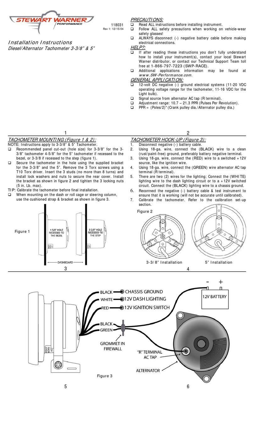
TACHOMETER MOUNTING (Figure 1 &2):
NOTE: Instructions apply to 3-3/8” & 5” Tachometer.
qRecommended panel cut-out (hole size) for 3-3/8” tachometer
is 3-3/8”.
qRecommended panel cut-out (hole size) for 5” tachometer is 4-
5/8” if recessed to the bezel, or 3-3/8” if recessed to the step
(Figure 1).
qSecure the tachometer in the hole using the supplied bracket
for the 3-3/8” and the 5”. Remove the 3 Torx screws using a
T10 Torx driver. Insert the 3 studs and install lock washers and
nuts to secure the rear cover. Install the bracket as shown in
figure 2 and tighten the 3 locking nuts (5 in. Lb. max).
qWhen mounting on the dash or roll cage or steering column,
use the cushioned strap & bracket as shown in figure 3.
3
TACHOMETER WIRING (Figure 3):
1. Disconnect negative (-) battery cable.
2. Using 18-ga. wire, connect the (BLACK) wire to a clean
(rust/paint-free) ground, preferably battery negative terminal.
3. Using 18-ga. wire, connect the (RED) wire to a switched +12V
source, like the ignition wire.
4. Using 18-ga. wire, connect the (GREEN) wire to the coil
negative or the tachometer terminal of the ignition module.
5. There are two (2) wires for the lighting. Connect the (WHITE)
lighting wire to the dash lighting circuit or to a +12V switched
circuit. Connect the (BLACK) lighting wire to a chassis ground.
6. Calibrate the pulses per revolution (PPR). Refer to the
programming set-up section.
7. Reconnect the negative (-) battery cable & test instrument to
ensure that it is working properly.
4
5 6
NEVER CONNECT GREEN WIRE TO THE COIL WHEN USING AN MSD OR SIMILAR HIGH
OUTPUT CAPACITIVE DISCHARGE STYLE IGNITION SYSTEM
Damage to the tachometer will occur—Connect GREEN wire to the tachometer terminal only.
Figure 3
Figure 1
3-3/8” Installation
5” Installation
Figure 2

CALIBRATION (PPR/Number of Cylinders):
Until recently, tachometers were calibrated based on the number of
cylinders in the engine. Now, there are all types of engine control
modules (ECMs - on-board computers) and distributor-less ignitions
and the old standard rule—”half the number of cylinders equals the
pulses per revolution (PPR)”—no longer applies. “Pulses per
revolution” relates to how many times the ignition fires per
crankshaft revolution. The tachometer outputs from the ECMs can
range from 1-PPR to 4-PPR for a V-8 engine. So, the new standard is
to refer to PPR instead of the number of cylinders.
SIGNAL INTERFACING:
Stewart Warner Performance tachometers are designed to work with
a wide variety of ignition types, including standard inductive [coil (-)
connection] and any ignition system with a clean tachometer output
signal. The input level can range from TTL 5V (outputs from newer
engine control modules) and 300-400 volt pulses from coil (-) on
most inductive ignition systems. Stewart Warner Performance
tachometers will operate on most traditional capacitive discharge
ignitions when connected to the ignition primary circuit. However,
for high-output CD’s (such as MSD) only connect to the tach output
terminal, never the coil primary. It’s best to consult our tech support
hotline if you’re unsure, rather than risk damage to the tachometer,
ignition or your warranties.
7
PROGRAMMING SET-UP (1, 2, 3, 4, 5, 6 PPR):
NOTE: Stewart Warner Performance Tachometers come pre-set
from the plant for a standard 8 cylinder (4 PPR) application.
1. Hold down the Enter/Change button while turning the ignition
switch on.
2. Release Enter/Change Button.
3. The shift-light will light for 1 second to indicate calibration set
mode has been accessed.
4. The needle will go to the previously set range, or the factory
default 4 PPR (indicated by pointer position of 4,000 RPM).
5. Press the Up/Clear or Down/Recall buttons to adjust for the
number of cylinders or pulses per rpm (the pointer will move to
indicate the new setting).
6. To exit programming mode at any time, momentarily press the
Enter/Change button to lock in the setting, or turn ignition
switch off, or if there are no buttons pressed for 5 seconds, the
tachometer will store all changes and exit to normal tachometer
operation.
8
SHIFT RPM SET-UP:
1. Turn ignition switch on, engine may be running, or not running,
as you wish!
2. Shift lamp will flash briefly to indicate proper shift-light
function.
3. Press and hold the ENTER button for 1 second until the
shift-light flashes. The flashing of the light in this case
acknowledges entry to the shift setting mode. The tachometer
pointer will now indicate the current shift-light RPM setting.
4. Press the Up/Clear or Down/Recall buttons to adjust the
shift-light RPM set point. The pointer will move up or down to
indicate the new setting.
5. To exit programming mode at any time, momentarily press the
Enter/Change button to lock in the setting, or turn ignition
switch off, or if there are no buttons pressed for 5 seconds, the
tachometer will store all changes and exit to normal tachometer
operation.
9
MEMORY RECALL & CLEAR OPERATIONS:
This Tachometer will store 1 current and 1 old peak RPM value. The
stored peak values are shifted through memory, so that the oldest
value is cleared and the current peak is stored as the previous peak
and a new current peak is acquired.
Recalling Current Peak RPM (engine running)
1. With the engine running, press and hold the Down/Recall
button. This will display the current peak RPM and will continue
to update even while the button is held down.
2. Release the button to return to normal operation.
Recalling Peak and Previous Peak RPM (engine not running)
1. Turn the ignition on (the pointer should indicate “0” RPM)
2. Press and hold the Down/Recall button to recall the current
peak RPM.
3. Release, then within 3 seconds, press and hold the
Down/Recall a second time to select the previous Peak RPM.
The shift-light will flash to indicate that you are viewing the
previous peak rpm.
4. Release button to return to return to normal operation.
Clearing Peak RPM
1. Turn the power on (the pointer should be at 0 RPM or
indicating actual RPM if engine is running).
2. Press the Up/Clear button for one second and release. The
oldest stored Peak RPM reading will be cleared, and the current
value will be stored as the previous Peak RPM reading.
10
TROUBLESHOOTING:
Q: My tachometer does not respond at all, what do I do?
A: Check all of the wiring connections and power to the
tachometer.
1. If the tachometer needle goes to zero when powered up,
but does not respond when the engine is started, there is
no signal to the green wire. Check to ensure that the
green wire is properly connected to a valid tach signal.
2. If the tachometer needle does not go to zero when
powered up, the tachometer is not grounded properly or
does not have power to the (RED) wire. Check to ensure
a good chassis ground, preferably at the battery ground.
Verify that the (RED) wire has a 12VDC supply.
Q: My tachometer does not read correctly, what do I do?
A: First, determine how the reading is incorrect (example: Double,
half, quarter etc.), then re-set the PPR calibration for correct
readings.
1. If the RPM reads double, re-set the PPR calibration for 1/2
of the current setting.
2. If the RPM reads 1/2, re-set the PPR calibration for 2 times
the current setting.
3. If the RPM reads 1/4, re-set the PPR calibration for 4 times
the current setting.
11
CLEANING DIRECTIONS:
qFor proper cleaning of instrumentation/accessories, use a glass
cleaner or mild detergent with a spray on and wipe method.
WARRANTY INFORMATION:
TWO (2) YEAR LIMITED WARRANTY. SWP products are
warranted against defects in workmanship and materials for a period
of two (2) years from the date of purchase. Proof-of-purchase is
required; otherwise, the warranty period shall default to two (2)
years from date-of-manufacture (as indicated by the date code on
the product). See detailed Warranty Policy for other Terms &
Conditions.
STEWART WARNER PERFORMANCE
1-866-SWP-RACE (797-7223)
www.SW-Performance.com
12
Other Stewart Warner Measuring Instrument manuals
Popular Measuring Instrument manuals by other brands
Zoom
Zoom F2 Operation manual
INTEGRA Merering
INTEGRA Merering AMFLO MAG Basic Mounting and operating instructions
Ion Energy Solutions
Ion Energy Solutions M54122 Installation instructions manual
BENDIX
BENDIX IN-20258 Maintenance manual
Enerpac
Enerpac DGR-1 instruction sheet
DELTA DORE
DELTA DORE CALYBOX 1020 WT user guide
