STI Guard Draw Stifner R User manual

1
Part Number
:
SG920VA030
Production Date: September,2021
△
0
Installation
and Operations instructions
for Guard Draw Stifner R
•
Thank you for purchasing this product.
•
This manual provides installation and handling instructions for this product, and precautions to be observed.
•
Before using this product, be sure to read "Safety Precautions" and use the product properly.
•
Keep this manual in a safe place, such as the glove box, and refer to it whenever necessary.
Important precautions are indicated with the following marks. Be sure to observe those precautions.
Warning
Precautions that you must observe for your safety.
[Failure to observe these precautions may result in death or serious injury.]
Caution
Precautions that you must observe for your safety and for your vehicle.
[Failure to observe these precautions may result in damages or accidents.]
*
Advice
Information
that
you
should
familiarize
yourself
with
.
Information that are useful.
If abnormal noise or vibration occurs while driving, pull over the car immediately to a safe place, and then inspect and
re-tighten the attaching bolts. If abnormalities persist, perform inspection and make necessary repairs immediately.

2
1.
Part Number and Applicable Model
Part Number Part Name Applicable Car Model
SG920VA030 STI R GUARD BAR WRX STI TYPE A ~
WRX TYPE A ~
2. Components
①Guard Bar Flexible Draw Stiffener Rear 1
②Pop nuts 4
③Flange bolts M8×25 4
④Pattern 1
*Please check the quantities of the component parts first. If there are any missing parts or discrepancies,
please contact your dealer
InstallationProcedures

3
3. Specification
This product protects the Flexible Draw Stiffener Rear from damage during goods loading and emergency braking
4.
Precautions During Installation
Caution
·
The contents of this manual is designed for automobile mechanics or those who have basic
knowledgeabout automobile maintenance. Do not let inexperienced persons to work alone,
as it could cause the vehicle toundergo dangerous troubles during driving. Toinstallthe
product properly for it to function as intended, it is recommended to perform the installation
procedure at an authorized SUBARU retailer.
·
Be sure to perform the work in accordance with the service manual for the relevant model
issued by SUBARUCORPORATION. and observe the precautions in this manual.
·
Tighten bolts and nuts according to specified torque. If not tightened with specified torque,
the bolts andnuts may become damaged or loose.
5. Work Procedure
Make sure to follow instructions in the service manual issued by SUBARU Corporation for
replacement instructions of related detachable parts when installing this part.
* The above diagram is for reference only and the shape and location of peripheral parts may vary depending on
vehicle specifications.
UPPER
LH
Guard Bar Flexible Draw Stiffener Rear
Overview of an Installed Guard Bar Flexible Draw Stiffener Rear
And
disconnect the negative
terminal of the battery before you start working on installation of the product.

4
Make the insections.
Valley Fold (Dotted Line)
Mountain Fold (Solid Line)
A: Introduction
1) Prepare the following items.
・φ5 drill
・φ16 hole saw
・Center punch and hammer
・Masking tape
・Protection materials for trunk (for example, protection sheet and tape)
・Flexible magnetic catch
B: Preparation for Processing
1) Disconnect the negative terminal of the battery.
For models with a battery sensor, disconnect the ground terminal from the battery sensor.
2) Disconnect the connector for the keyless access interior rear antenna in the trunk.
* Important
・Do not remove the antenna assembly from the body of the vehicle. It will cause rattling and noise.
C: Preparation of Pattern
1) Adjust the pattern into the required shape
2) Fixing the shape of the pattern
Secure the parts along the
bold line with tape.
UPPER
LH

5
3) Positioning of the pattern
Push the pop nuts through the φ16 holes on the pattern and position them into the 2 φ16 holes on the
underside of the rear bulkhead.
(The figure below is an example of the left-hand side.)
Once the position is determined, secure the rear bulkhead, pattern and pop nut with tape.
4) Fixing the pattern
Secure the pattern with tape at the points indicated in the figure below
while being careful not to leave any sagging or gaps between the pattern
and the rear bulkhead.
Pattern
Pop Nut
φ16 Hole on the Underside of the Rear Bulkhead
UPPER
LH
UPPER
LH
Tape

6
D: Processing of Vehicle Body
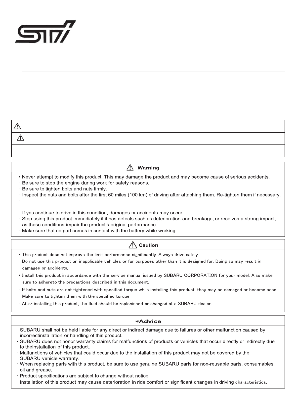
1) Positioning for drilling
Mark the center punch in the center of the cross-shaped cutout in the pattern. (2 locations,
left and right. The figure below is an example of the left side.) Once you have finished
marking the center punches, remove the pattern and pop nuts once.
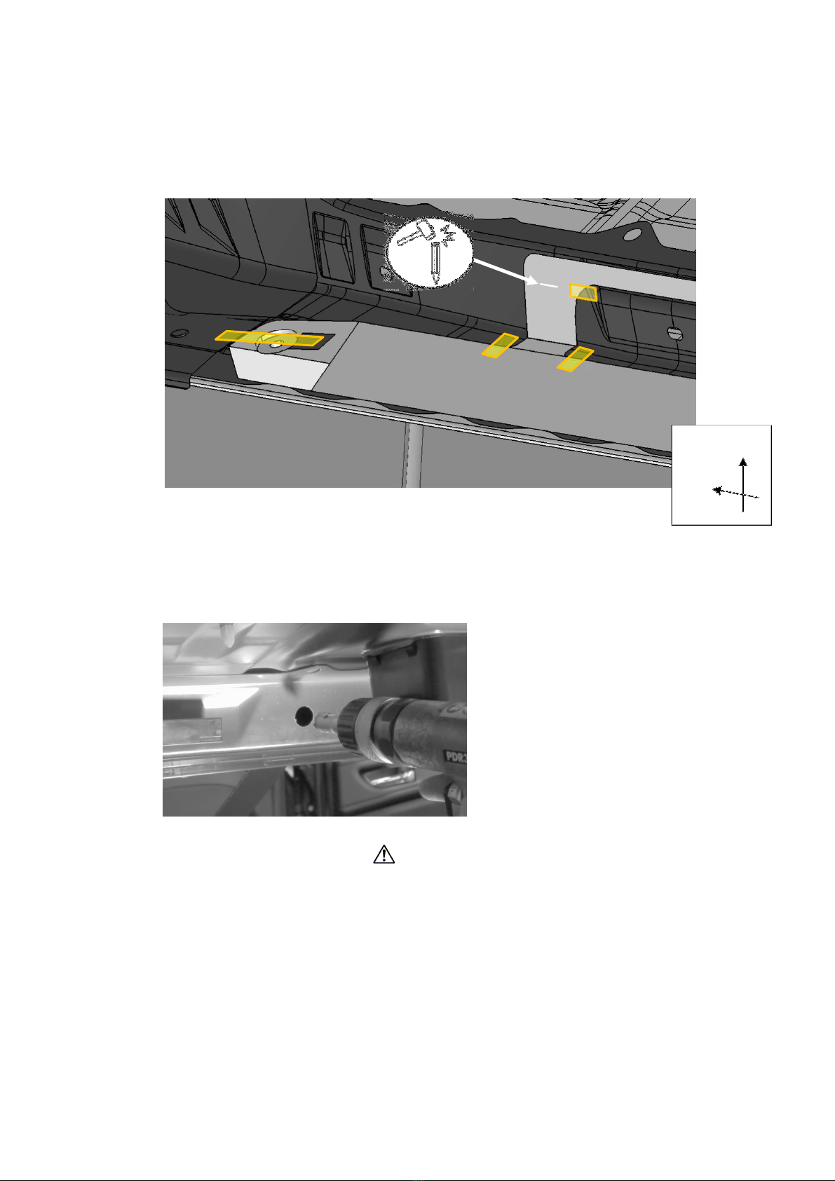
2) Drilling process
Drilling holes in the 2 positions of the center marking.
Use a φ5mm drill to drill a test hole and a φ16 hole saw to drill the mounting hole in the 2 locations.
(The figure below is an example of the right side.)
CAUTION
When drilling, pay attention to the following points in order to prevent abnormal noise and rust.
1. The trunk should be protected from flying chips.
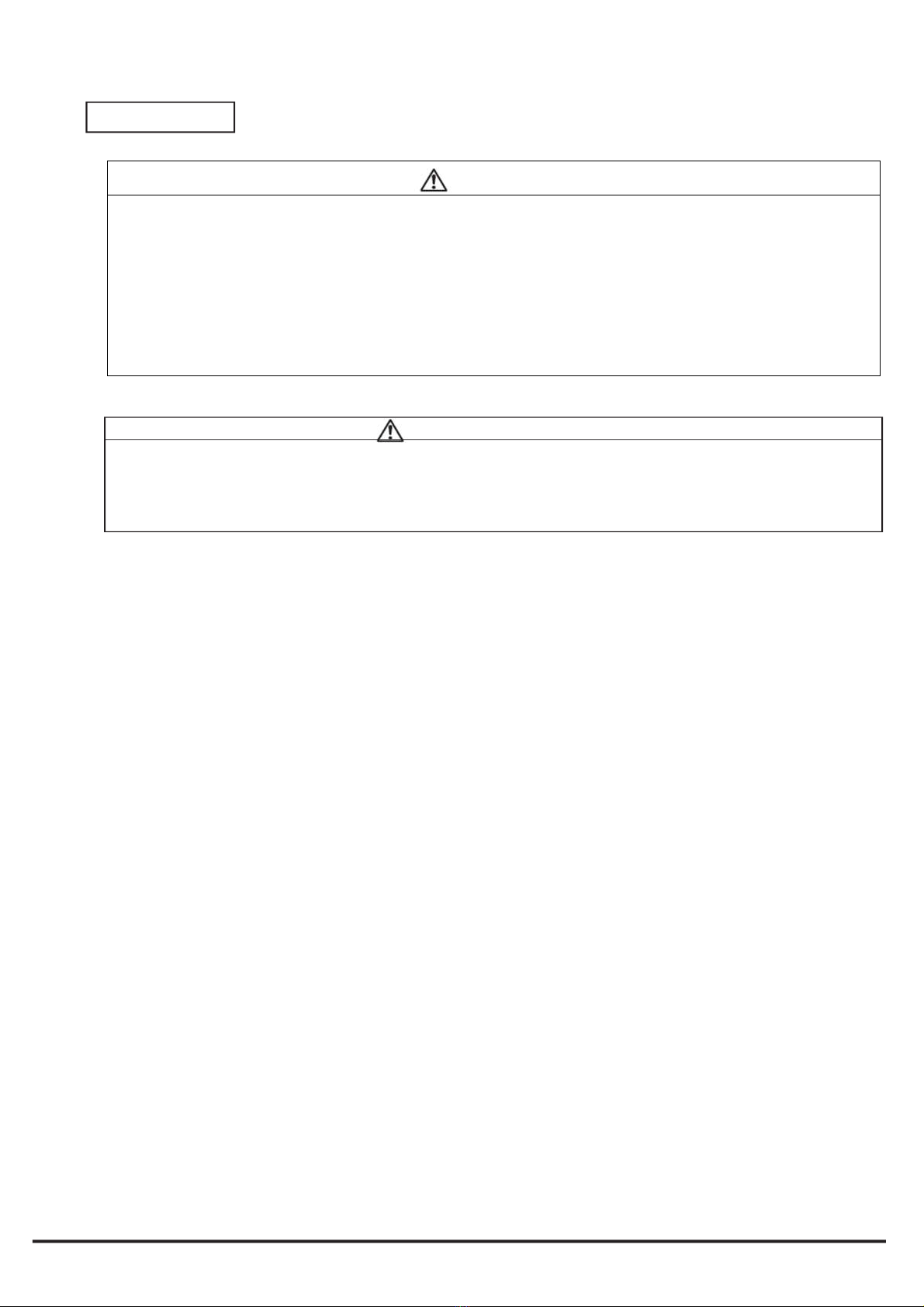
2.The rear bulkheadhas a bag structure.Work carefully to prevent chipsand drill debris from
entering the inside of the bulkhead.
3. Position the hole saw orthogonally to the work surface.
4. To prevent damage from chips, remove them frequently during work.
Before the hole saw blade penetrates, move the hole saw away from the work area and
remove the chips inside the saw.
5. Remove all burrs from the inside and outside of the hole after drilling.
6. After drilling, remove any chips scattered inside the rear bulkhead and trunk.
For the inside of the rear bulkhead, use a flexible magnetic catch to thoroughly remove the
chips.
7. Apply touch-up paint to the processed area and allow it to dry thoroughly.
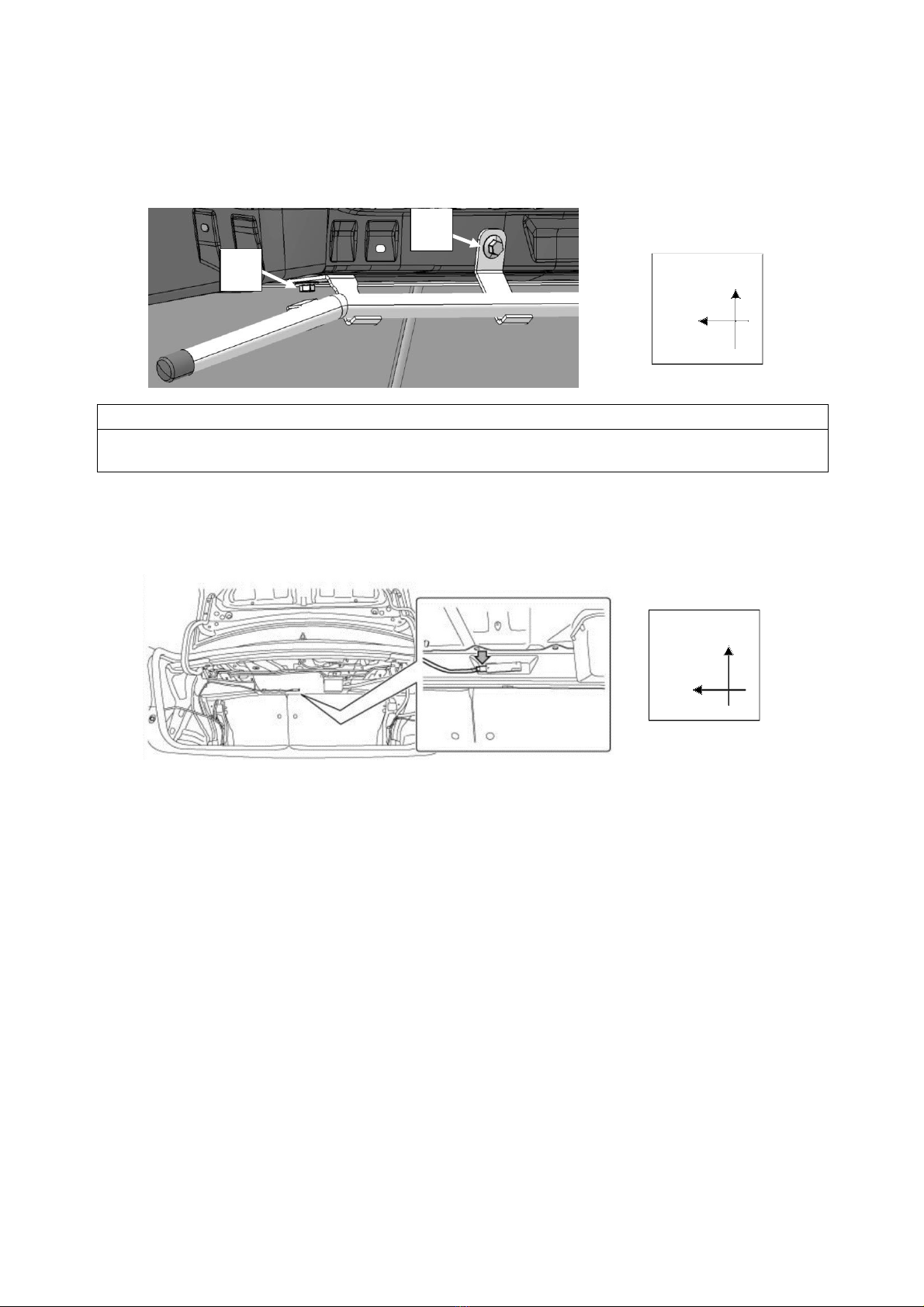
UPPER
LH

7
E: Installation
1) Push pop nuts into the 2 holes made in the previous steps at the rear side of the rear bulkhead.
(The figure below is an example of the right side.)
2) Insert the bolts into the 2 holes on the underside of the guard bar and temporarily assemble them with the
pop nuts.
(The figure below is an example of the left-hand side.)
3) Installation of the guard bar to the vehicle body
1. Insert the temporarily assembled pop nut on the underside of the guard bar into the φ16 hole on the underside
of the rear bulkhead.
(The figure below is an example of the left-hand side.)
φ16 Hole on the Underside of the Rear Bulkhead
UPPER
LH

8
2. Temporarily fasten the 2 bolts on the rear side of the rear bulkhead.
3. Temporarily fasten the 2 bolts on the underside of the rear bulkhead.
4. Retighten the 4 bolts temporarily fastened in Steps 2 and 3 a little at a time each, and finally fasten all
4 bolts with 5 Nm.
*Advice
・Tighten the 4 bolts a little at a time each to ensure even tightening.
Applying full torque to one bolt at a time may damage the pop nut.
F: Restoration
1) Plug in the connector for the keyless access interior rear antenna in the trunk.
2) Reconnect the negative terminal of the battery.
For models with a battery sensor, connect the ground terminal from the battery sensor.
3
2
UPPER
LH
UPPER
LH

9
Handling Precautions
SUBARU CORPORATION
Warning
・If abnormal noise or vibration occurs while driving, pull over the car immediately to a safe
place, and then inspect and re-tighten the attaching bolts. If abnormalities persist, perform
inspection and make necessary repairs immediately.
If you continue to drive in this
condition, damages or accidents may occur.
・
Inspect the nuts and bolts after the first 60 miles (100 km) of driving
and periodically
after
attaching them. Re-tighten them if necessary.
・Please do not use this product for other than applicable models.
To customers
・
We recommend that this product be installed at an authorized Subaru maintenance facility
to ensureproper installation and function.
Caution
CautionCaution
Caution

Part Number
:
SG920VA040
Production Date: September,2021
△
0
Installation
and Operations instructions
for LATERAL LINK SET
•
Thank you for purchasing this product.
•
This manual provides installation and handling instructions for this product, and precautions to be observed.
•
Before using this product, be sure to read "Safety Precautions" and use the product properly.
•
Keep this manual in a safe place, such as the glove box, and refer to it whenever necessary.
Important precautions are indicated with the following marks. Be sure to observe those precautions.
Warning
Precautions that you must observe for your safety.
[Failure to observe these precautions may result in death or serious injury.]
Caution
Precautions that you must observe for your safety and for your vehicle.
[Failure to observe these precautions may result in damages or accidents.]
*
Advice
Information
that
you
should
familiarize
yourself
with
.
Information that are useful.
- l -
If abnormal noise or vibration occurs while driving, pull over the car immediately to a safe place, and then inspect and
re-tighten the attaching bolts. If abnormalities persist, perform inspection and make necessary repairs immediately.

1.
Part Number and Applicable Model
P
a
rt
number
Part
Name
Applicable
Model
SG920VA040
STI LATERAL LINK SET
WRX
STI A TYPE~
WRX
STI Limited A TYPE~
2.
Components
*
Check the number of items included first. If any items are missing or different, contact the place of purchase.
3.
Specifications
Changed the rubber bushes of the front and rear lateral links to pillow ball bushes
4.
Precautions During Installation
5.
Parts that Cannot be Replaced at the Same Time or Reused
Replace self-locking nuts and flange nuts according to the service manual issued by Subaru
Corporation.
Installation Procedures
Lateral link set Front (RH/LH)
each
1
Lateral link set Rear (RH/LH)
each 1
Washer A (Outer Diameter
Φ22, Inner Diameter Φ14)
2
Washer
B
(Outer Diameter
Φ22, Inner Diameter Φ
12.5
)
2
Caution
・Always tighten the bushing in the state where the vehicle is at curb weight and the wheels are in full contact
with the ground.
・When the wheel alignment has been adjusted, perform adjustment of the VDC sensor midpoint setting mode.
・Do not apply impact to the sensor assembly -
headlight beam leveler or forcibly move the arm. Doing so may
cause sensor damage and malfunction.
And disconnect the negative
terminal of the battery before you start working on installation of the product.

6
66
6.
..
.
Installation Procedure
Please refer to the service manual issued by SUBARU CORPORATION. for the details of the work.
*Please check the wheel alignment and adjust if necessary.
Caution
・When installing the lateral link assembly - front, install the washer A and B on the nut side of the
pillow ball bushing.
Lateral
Link Front
Lateral
Link
Rear
Washer B
Washer
A
・When the lateral link parts are attached / detached or replaced, it is necessary to initialize or
reinitialize the auto headlamp leveler system.
Please perform the re-initialization work according to the service manual body lighting system auto
headlamp leveler system issued by SUBARU Corporation.

Handling Precautions
Caution
・
We recommend that this product be installed at an authorized SUBARU maintenance facility to
ensureproper installation and function.
・Be sure to use this product as a set. If you combine it with links with different specifications, you will not
get the original performance.
・Installation of this product may cause deterioration of ride comfort and major changes in driving
characteristics.
Warning
・If abnormal noise or vibration occurs while driving, pull over the car immediately to a safe place,
and then inspect and re-tighten the attaching bolts. If abnormalities persist, perform inspection
and make necessary repairs immediately.
If you continue to drive in this condition, damages or
accidents may occur.
・
Inspect the nuts and bolts after the first 60 miles (100 km) of driving
and periodically
after attaching
them. Re-tighten them if necessary.
・Please do not use this product for other than applicable models.
・By changing the rubber bush part to a pillow ball, this product makes the movement of the vehicle
sharper with respect to the input from the road surface and the input from the steering, but it does
not dramatically improve the limit performance itself. Please try to drive safely as before the
replacement.
To customers

SUBARU CORPORATION
-9-
This manual suits for next models
1
Other STI Automobile Accessories manuals
Popular Automobile Accessories manuals by other brands

EOinnovations
EOinnovations EOC3103 instruction manual

Directed
Directed VW02 Firmware Specific Guide

ATD Tools
ATD Tools SPI-77201 user manual

Whelen Engineering Company
Whelen Engineering Company 6-button WeCan Configuration guide

Cruz
Cruz 925-77 Series Assembly instructions

AA Products
AA Products RB0006 instruction manual