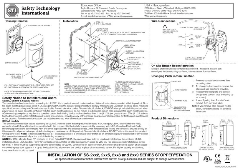
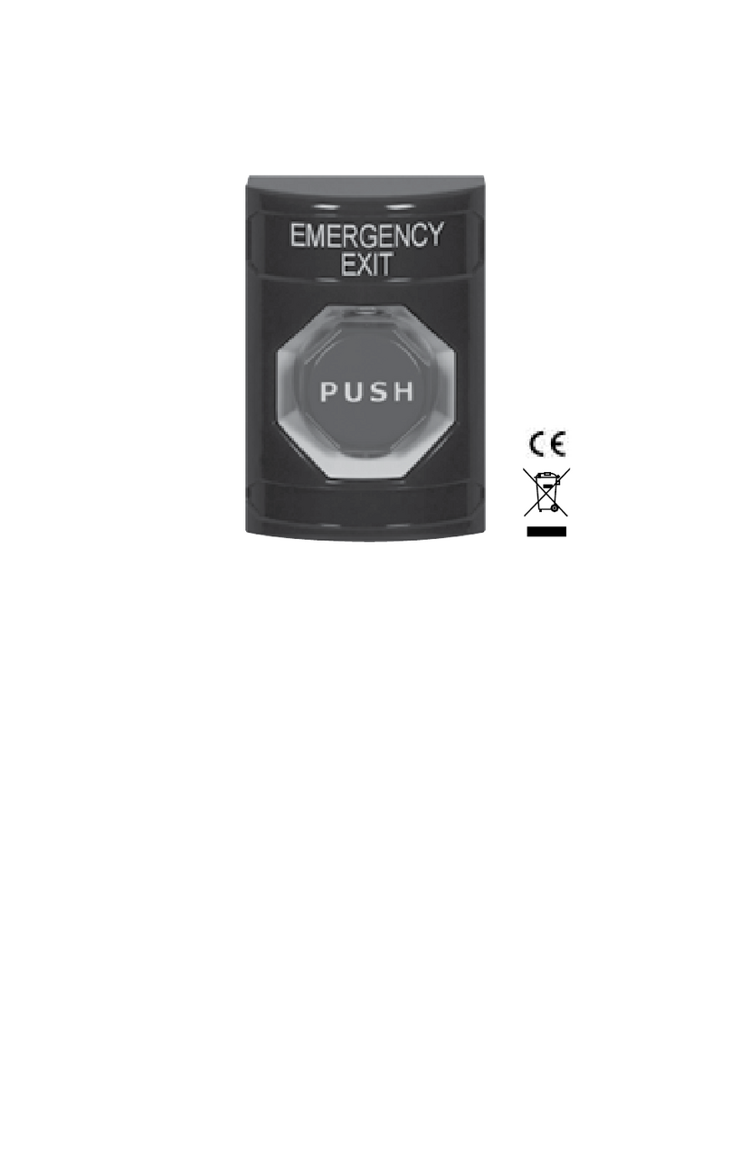
STI SS2 6 Series User manual

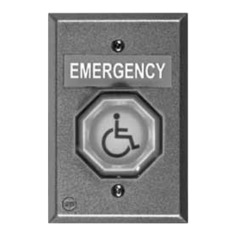
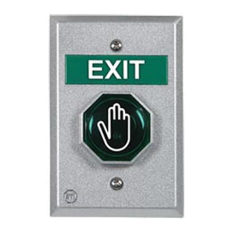
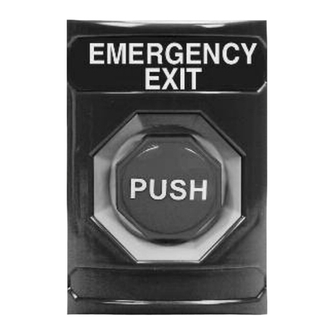
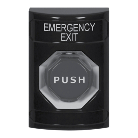
Illuminated Stopper®Station
Push Button
Model SS2xx6
Rely on STI®

- 2 -
Switch Rating
2 momentary independent Form “C” contacts, DPDT
Rated at: 10A, 125/250VAC; ½ HP
6A, 30 VDC
100,000 operations
Temperature: 32°F to 120°F (0°C to 49°C)
NOTE
LED connection is polarity
sensitive. If LED does not light,
switch positive and negative wiring
or remove LED and rotate 180°. 24
volt is included and will operate on
12 volts; however not as bright. 12
volt LED’s are also available.
4.880 in
[123.95 mm]
3.218 in
[81.74 mm]
.875 in
[22.23 mm]
1.625 in
[41.28 mm]
TOP TAB
A
B
#6-32 x 1 in. PHILLIPS
HEAD MACHINE SCREW
(2) PROVIDED
KIT-71100A-COLOR
BACKBOX
(OPTIONAL)
#6 x 1-1/4 in.
PHILLIPS PAN HEAD SCREW
(4) PROVIDED w/ KIT-71100A-COLOR
#8-32 x 3/8 in. SCREW
DRILL POINT PROVIDED TOP & BOTTOM
FOR 1/2 in. CONDUIT. DRILL AS NEEDED
#8-10 7/8 in. ANCHOR
(4) PROVIDED w/ KIT-71100A-COLOR
DRILL (4) 3/16 in. DIAMETER HOLES
DRILL OUT THE (4) MOUNTING
HOLES, ONE IN EACH CORNER,
USING 5/32 in. DRILL BIT
BACKBOX MUST BE MOUNTED
WITH ARROWS POINTING UP
1.625 in.
(41.28mm)
1.575 in.
(40.01mm)
#6-32 x 1 in. PHILLIPS
HEAD MACHINE SCREW
(2) PROVIDED
#8-32 x 3/8 in. SCREW
STEP A COMPLETED
TOP TAB
NC
NO
COM
LED
TERMINALS
Dimensions

- 3 -
Safety Notice to Installers and Users
This push button has been tested according to UL2017. It is important to read, understand
and follow all instructions provided with this product. Non-fire alarm initiating devices
are listed in UL category UEHX. It is the installer’s responsibility to comply with NEC and
Canadian electrical code, mounting specifications according to ADA and other applicable fire
and electrical codes. To avoid electrical shock , DO NOT attempt to install this product when
power is on. To avoid possible confusion with fire alarm initiating devices, do not mount a red
stopper station near a manual fire alarm initiating device. ADA mounting compliance requires
the operable part of the initiating device shall not be less than 1.1m (3 1/2 ft.) or greater
than 1.37m (4 1/2 ft.) above finished floor service. After installation and testing are complete,
provide a copy of this manual to all personnel responsible for testing and maintenance of
this product. Push buttons for outdoor use must be mounted with STI outdoor rated covers.
Remarques sur l’installation: Ce bouton-poussoir a été testé selon UL2017. Il est important
de lire, de comprendre et de suivre toutes les instructions fournies avec ce produit. Les
dispositifs de déclenchement d’alertes non incendie sont répertoriés sous la catégorie UL
UEHX. Il incombe à l’installateur de se conformer aux normes NEC et Code canadien de
l’électricité, aux spécifications de montage selon l’ADA et aux autres codes de prévention
des incendies et de l’électricité en vigueur. Pour éviter un choc électrique, NE tentez PAS
d’installer ce produit lorsqu’il est sous tension. Pour éviter toute confusion possible avec
les dispositifs de déclenchement d’alertes d’incendie, n’installez pas un avertisseur Stopper
rouge à proximité d’un dispositif de déclenchement d’alarme d’in cendie manuel. La
conformité aux règles d’installation de l’ADA exige que la partie utilisable du dispositif de
déclenchement soit installée à une hauteur située entre 1,1 m (3 1/2 pi) et 1,37 m (4 1/2 pi)
au-dessus du plancher fini. Une fois l’installation et les essais terminés, vous devez fournir
une copie de ce manuel à l’ensemble du personnel chargé de l’essai et de l’entretien de
ce produit. Les boutons poussoirs pour utilisation à l’extérieur doivent être installés avec
couvercles pour l’extérieur de STI.
- 4 -
Install or Remove Contact Block
INSTALL
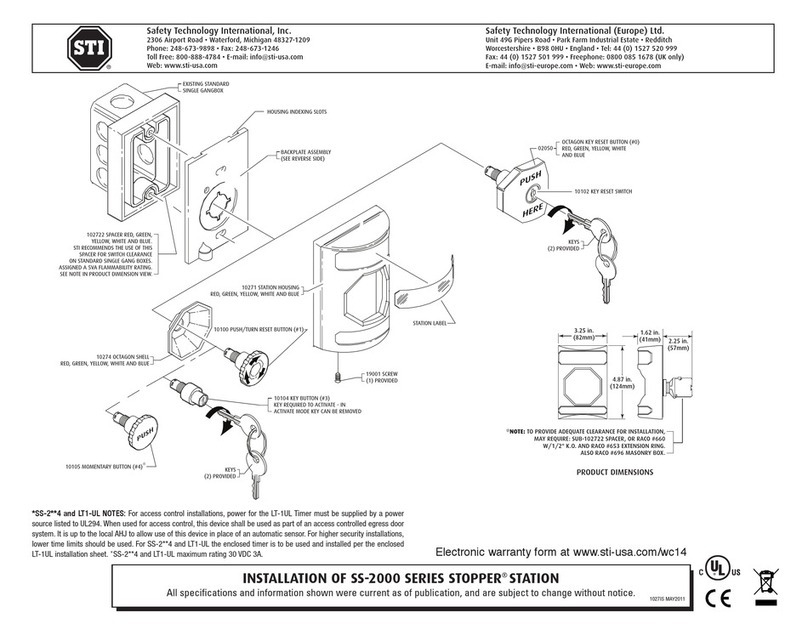
To attach, align tabs (as shown) and gently snap top then bottom. Be sure
to hear BOTH tabs snap into place. (Can be reversed if wiring comes from
the bottom of the box.)
REMOVE
Repeat STEP A for the top and bottom tab before pulling on contact block.
Step A: Position small flat screwdriver blade under tab and gently rotate until
tab disengages. The contact block will rotate a little. DO NOT PULL YET.
Step B: Repeat for opposite tab.
Step C: When both tabs are disengaged, pull the contact block straight off.
4.880 in
[123.95 mm]
3.218 in
[81.74 mm]
.875 in
[22.23 mm]
1.625 in
[41.28 mm]
TOP TAB
A
B
#6-32 x 1 in. PHILLIPS
HEAD MACHINE SCREW
(2) PROVIDED
KIT-71100A-COLOR
BACKBOX
(OPTIONAL)
#6 x 1-1/4 in.
PHILLIPS PAN HEAD SCREW
(4) PROVIDED w/ KIT-71100A-COLOR
#8-32 x 3/8 in. SCREW
DRILL POINT PROVIDED TOP & BOTTOM
FOR 1/2 in. CONDUIT. DRILL AS NEEDED
#8-10 7/8 in. ANCHOR
(4) PROVIDED w/ KIT-71100A-COLOR
DRILL (4) 3/16 in. DIAMETER HOLES
DRILL OUT THE (4) MOUNTING
HOLES, ONE IN EACH CORNER,
USING 5/32 in. DRILL BIT
BACKBOX MUST BE MOUNTED
WITH ARROWS POINTING UP
1.625 in.
(41.28mm)
1.575 in.
(40.01mm)
#6-32 x 1 in. PHILLIPS
HEAD MACHINE SCREW
(2) PROVIDED
#8-32 x 3/8 in. SCREW
STEP A COMPLETED
TOP TAB
NC
NO
COM
LED
TERMINALS
STEP A
STEP B
STEP C

- 5 -
4.880 in
[123.95 mm]
3.218 in
[81.74 mm]
.875 in
[22.23 mm]
1.625 in
[41.28 mm]
TOP TAB
A
B
#6-32 x 1 in. PHILLIPS
HEAD MACHINE SCREW
(2) PROVIDED
KIT-71100A-COLOR
BACKBOX
(OPTIONAL)
#6 x 1-1/4 in.
PHILLIPS PAN HEAD SCREW
(4) PROVIDED w/ KIT-71100A-COLOR
#8-32 x 3/8 in. SCREW
DRILL POINT PROVIDED TOP & BOTTOM
FOR 1/2 in. CONDUIT. DRILL AS NEEDED
#8-10 7/8 in. ANCHOR
(4) PROVIDED w/ KIT-71100A-COLOR
DRILL (4) 3/16 in. DIAMETER HOLES
DRILL OUT THE (4) MOUNTING
HOLES, ONE IN EACH CORNER,
USING 5/32 in. DRILL BIT
BACKBOX MUST BE MOUNTED
WITH ARROWS POINTING UP
1.625 in.
(41.28mm)
1.575 in.
(40.01mm)
#6-32 x 1 in. PHILLIPS
HEAD MACHINE SCREW
(2) PROVIDED
#8-32 x 3/8 in. SCREW
STEP A COMPLETED
TOP TAB
NC
NO
COM
LED
TERMINALS

- 6 -
4.880 in
[123.95 mm]
3.218 in
[81.74 mm]
.875 in
[22.23 mm]
1.625 in
[41.28 mm]
TOP TAB
A
B
#6-32 x 1 in. PHILLIPS
HEAD MACHINE SCREW
(2) PROVIDED
KIT-71100A-COLOR
BACKBOX
(OPTIONAL)
#6 x 1-1/4 in.
PHILLIPS PAN HEAD SCREW
(4) PROVIDED w/ KIT-71100A-COLOR
#8-32 x 3/8 in. SCREW
DRILL POINT PROVIDED TOP & BOTTOM
FOR 1/2 in. CONDUIT. DRILL AS NEEDED
#8-10 7/8 in. ANCHOR
(4) PROVIDED w/ KIT-71100A-COLOR
DRILL (4) 3/16 in. DIAMETER HOLES
DRILL OUT THE (4) MOUNTING
HOLES, ONE IN EACH CORNER,
USING 5/32 in. DRILL BIT
BACKBOX MUST BE MOUNTED
WITH ARROWS POINTING UP
1.625 in.
(41.28mm)
1.575 in.
(40.01mm)
#6-32 x 1 in. PHILLIPS
HEAD MACHINE SCREW
(2) PROVIDED
#8-32 x 3/8 in. SCREW
STEP A COMPLETED
TOP TAB
NC
NO
COM
LED
TERMINALS
Mounting

- 7 -
4.880 in
[123.95 mm]
3.218 in
[81.74 mm]
.875 in
[22.23 mm]
1.625 in
[41.28 mm]
TOP TAB
A
B
#6-32 x 1 in. PHILLIPS
HEAD MACHINE SCREW
(2) PROVIDED
KIT-71100A-COLOR
BACKBOX
(OPTIONAL)
#6 x 1-1/4 in.
PHILLIPS PAN HEAD SCREW
(4) PROVIDED w/ KIT-71100A-COLOR
#8-32 x 3/8 in. SCREW
DRILL POINT PROVIDED TOP & BOTTOM
FOR 1/2 in. CONDUIT. DRILL AS NEEDED
#8-10 7/8 in. ANCHOR
(4) PROVIDED w/ KIT-71100A-COLOR
DRILL (4) 3/16 in. DIAMETER HOLES
DRILL OUT THE (4) MOUNTING
HOLES, ONE IN EACH CORNER,
USING 5/32 in. DRILL BIT
BACKBOX MUST BE MOUNTED
WITH ARROWS POINTING UP
1.625 in.
(41.28mm)
1.575 in.
(40.01mm)
#6-32 x 1 in. PHILLIPS
HEAD MACHINE SCREW
(2) PROVIDED
#8-32 x 3/8 in. SCREW
STEP A COMPLETED
TOP TAB
NC
NO
COM
LED
TERMINALS
Surface Mounting

Printed in USA Inst. Sht. SS2xx6 JULY2018
2306 Airport Rd • Waterford, MI 48327, USA
Phone: 248-673-9898 • Fax: 248-673-1246
[email protected] • www.sti-usa.com
Taylor House • 34 Sherwood Road • Bromsgrove, Worcestershire • B60 3DR • England
Tel: +44 (0)1527 520 999 • Fax: +44 (0)1527 501 999
[email protected] • www.sti-emea.com
Warranty
Three year guarantee against breakage of polycarbonate in normal use (one year on electro
mechanical and electronic components).
Electronic warranty form at www.sti-usa.com/wc14.
WARNING: This product can expose you to chemicals including Dichloromethane,
which is known to the State of California to cause cancer, and Bisphenol A (BPA),
which is known to the State of California to cause birth defects or other reproductive
harm. For more information go to www.P65Warnings.ca.gov.
Testing Approvals
It has been tested and approved or listed by:
· Underwriter Laboratories and cUL No. S7255.
This manual suits for next models
1
Table of contents
Other STI Switch manuals

STI
STI UB-1TF User manual

STI
STI Stopper Station SS2 8 Series Quick guide

STI
STI D40R-SP User manual

STI
STI SS2 2 Series User manual

STI
STI UB-2 User manual

STI
STI CMCP423VTA User manual

STI
STI Stopper Station Series User manual

STI
STI UB-1PN User manual

STI
STI MF Series User manual

STI
STI CMCP310 Series User manual
Popular Switch manuals by other brands

Intellinet
Intellinet 560917 user manual

Cleveland Controls
Cleveland Controls AFS-460-136 quick start guide

Giga-tronics
Giga-tronics ASCOR Series 8000 Getting started guide

Ruijie
Ruijie RG-S6510-32CQ Hardware installation and reference guide

Extron electronics
Extron electronics IN1508 user manual

ZIGBEE
ZIGBEE CP-DS112 user manual