manuals.online logo
Brands
  1. Home
  2. •
  3. Brands
  4. •
  5. STIEBEL ELTRON
  6. •
  7. Temperature Controllers
  8. •
  9. STIEBEL ELTRON RTF-TC User manual

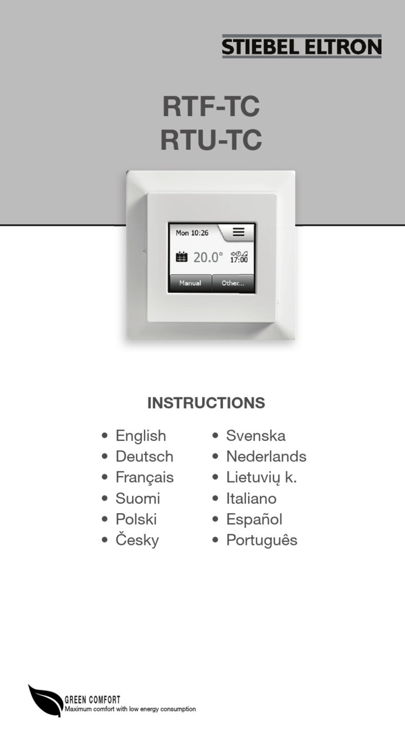
STIEBEL ELTRON RTF-TC User manual

Other manuals for RTF-TC

1

This manual suits for next models

1

Other STIEBEL ELTRON Temperature Controllers manuals

STIEBEL ELTRON RTU-S UP Stiebel User manual

STIEBEL ELTRON

STIEBEL ELTRON RTU-S UP Stiebel User manual

STIEBEL ELTRON RTF-TC User manual

STIEBEL ELTRON

STIEBEL ELTRON RTF-TC User manual

STIEBEL ELTRON EASYTRON Connect ERT User manual

STIEBEL ELTRON

STIEBEL ELTRON EASYTRON Connect ERT User manual

STIEBEL ELTRON SOM 9s User manual

STIEBEL ELTRON

STIEBEL ELTRON SOM 9s User manual

Popular Temperature Controllers manuals by other brands

Brookfield TC Series Operator's manual

Brookfield

Brookfield TC Series Operator's manual

Nibe HPAC 45 Installer manual

Nibe

Nibe HPAC 45 Installer manual

Auber TD100 instruction manual

Auber

Auber TD100 instruction manual

IntelliSense INTELLITEMP T-1000 installation instructions

IntelliSense

IntelliSense INTELLITEMP T-1000 installation instructions

Swegon LUNAd MB Instructions for use

Swegon

Swegon LUNAd MB Instructions for use

Lucky Reptile Thermo Control II Operation instructions

Lucky Reptile

Lucky Reptile Thermo Control II Operation instructions

SMC Networks Thermo-con INR-244-639 Operation manual

SMC Networks

SMC Networks Thermo-con INR-244-639 Operation manual

SENSORMETRIX Argon 100 manual

SENSORMETRIX

SENSORMETRIX Argon 100 manual

Fuji Electric PXE4 instruction manual

Fuji Electric

Fuji Electric PXE4 instruction manual

Yuyao gongyi XMT-808 series Operation manual

Yuyao gongyi

Yuyao gongyi XMT-808 series Operation manual

eltherm Ex-TC It Series operating instructions

eltherm

eltherm Ex-TC It Series operating instructions

Selec TC544C user guide

Selec

Selec TC544C user guide

P.W. KEY rt-208gt operating manual

P.W. KEY

P.W. KEY rt-208gt operating manual

Omron C200H-TV Series Operation manual

Omron

Omron C200H-TV Series Operation manual

BH Thermal BriskONE owner's manual

BH Thermal

BH Thermal BriskONE owner's manual

West Control Solutions KS 45 Operation Notes

West Control Solutions

West Control Solutions KS 45 Operation Notes

Opt Lasers TEC-8A-24V-PID-HC operating manual

Opt Lasers

Opt Lasers TEC-8A-24V-PID-HC operating manual

Vaillant VR 92/3 Operating and installation instructions

Vaillant

Vaillant VR 92/3 Operating and installation instructions

manuals.online logo
manuals.online logoBrands
  • About & Mission
  • Contact us
  • Privacy Policy
  • Terms and Conditions

Copyright 2025 Manuals.Online. All Rights Reserved.

RTF-TC
RTU-TC
RTF-TC
RTU-TC
• English
• Deutsch
• Français
• Suomi
• Polski
• Česky
• Svenska
INSTRUCTIONS
GREEN COMFORT
Maximum comfort with low energy consumption
• Nederlands
• Lietuvių k.
• Italiano
• Español
• Português
• Magyar
© 2020 OJ Electronics A/S
2© 2020 OJ Electronics A/S
ILLUSTRATIONS
Pages.................................................................................... 3
INSTRUCTIONS
English.................................................................................. 7
Deutsch .............................................................................. 12
Français .............................................................................. 17
Suomi ................................................................................. 22
Polski .................................................................................. 27
Česky.................................................................................. 32
Svenska.............................................................................. 37
Nederlands......................................................................... 42
Lietuvių k. ........................................................................... 47
Italiano................................................................................ 52
Español............................................................................... 57
Português ........................................................................... 62
Magyar ............................................................................... 69
3
© 2020 OJ Electronics A/S
RTF-TC
RTU-TC
© 2020 OJ Electronics A/S
ILLUSTRATIONS
Pages.................................................................................... 3
INSTRUCTIONS
English.................................................................................. 7
Deutsch .............................................................................. 12
Français .............................................................................. 17
Suomi ................................................................................. 22
Polski .................................................................................. 27
Česky.................................................................................. 32
Svenska.............................................................................. 37
Nederlands......................................................................... 42
Lietuvių k. ........................................................................... 47
Italiano................................................................................ 52
Español............................................................................... 57
Português ........................................................................... 62
Magyar ............................................................................... 69
BR1017A02
Fig. 1
Fig. 2
BR1017A01
BR1017A01BR1017A02
4© 2020 OJ Electronics A/S © 2020 OJ Electronics A/S
RTF-TC / RTU-TC
BR1017A03A
1.5m
1
2
4
3≤ 25°
BR1017A04D
BR1017A03a
BR1017A05A
653 421
N
L
Fig. 3
Fig. 4
BR1017A04d
© 2020 OJ Electronics A/S 5
© 2020 OJ Electronics A/S
RTF-TC / RTU-TC RTF-TC / RTU-TC
BR1017A03a
BR1017A05A
653 421
N
L
BR1017A06
Fig. 5
Fig. 6
BR1017A05aBR1017A06
BR1017A04d
© 2020 OJ Electronics A/S
6© 2018 OJ Electronics A/S
RTF-TC / RTU-TC
1
2
3
4
4
BR1017A14BR1017A07
Fig. 7
Fig. 8
BR1017A07
ON
OFF
1
2
Manual Menu
Auto
BR1017A17
Fig. 9
7
© 2020 OJ Electronics A/S
RTF-TC
RTU-TC
© 2018 OJ Electronics A/S
RTF-TC / RTU-TC
FIG. 1 - CONTENT
• Thermostat
• Sensor
The thermostat is an electronic PWM/PI thermostat for tempera-
ture control by means of an NTC sensor located either externally or
internally within the thermostat.
The thermostat is for flush mounting in a wall socket. A baseplate
for wall mounting is also available.
This thermostat can be used as a controller for electric room heat-
ing pursuant to EN50559.*
* Only valid for RTF-TC (MCD5-1999)
Product programme
RTF-TC (MCD5-1999) Clock-thermostat with two sensors:
floor sensor and built-in room sensor.
RTU-TC (MCC5-1999) Clock-thermostat with built-in room
sensor.
FIG. 2 - WARNING – Important Safety Instructions
Disconnect the power supply before carrying out any installation or
maintenance work on this thermostat and associated compo-
nents. The thermostat and associated components should only be
installed by a competent person (i.e. a qualified electrician). Electri-
cal installation must be in accordance with appropriate statutory
regulations.
FIG. 3 - THERMOSTAT PLACEMENT
Mounting of sensor
The floor sensor contains a safety extra-low voltage (SELV) circuit,
allowing it to be placed as close to the floor surface as possible
without having to take account of the risk of shock should the sen-
sor cable become damaged. The two wires connecting the sensor
to the mounting box must be additionally insulated, e.g. shrink flex.
Instruction
English
BR1017A14BR1017A07
BR1017A17
8© 2020 OJ Electronics A/S © 2020 OJ Electronics A/S
To prevent loose wires in the fixed installation from coming into
contact with the terminal block for the floor sensor, they must be
restrained using cable ties.
It is strongly recommended that the cable and sensor are placed in
a non-conductive installation pipe embedded in the floor. The end
of the pipe must be sealed and the pipe placed as high as possible
in the concrete layer. The sensor cable must be led through a
separate conduit or segregated from power cables.
The floor sensor must be centred between loops of heating cable.
The sensor cable may be extended up to 100 m by means of a
separate two-core cable. Two vacant wires in a multi-core cable
used, for example, to supply current to the floor heating cable must
not be used. The switching peaks of such current supply lines may
create interference signals that prevent optimum thermostat func-
tion. If a shielded cable is used, the shield must not be connected
to earth (PE). The two-core cable must be placed in a separate
pipe or segregated from power cables in some other way.
Mounting of thermostat with built-in sensor
The room sensor is used for comfort temperature regulation in
rooms. The thermostat should be mounted on the wall approx.
1.5 m above the floor in such a way as to allow free air circulation
around it. Draughts and direct sunlight or other heat sources must
be avoided.
FIG. 4 - OPENING THE THERMOSTAT
1. Slide the power button down to O “0”.
2. Release the front cover ONLY by inserting a small screwdriver
into the slot at the centre of the bottom side of the front cover to
press and hold the catch securing the front cover.
3. Then carefully pull the front cover away, initially from the lower
part of the thermostat, then from the upper part of the thermo-
stat.
FIG. 5 - CONNECTIONS
Connect the wires in accordance with the diagram. The wires must
be connected as follows:
Term. 1: Neutral (N)
Term. 2: Live (L)
Term. 3-4: Output, max. 16 A
Term. X: Do not connect
RTF-TC / RTU-TC English
Term. 5-6: External floor sensor (RTF-TC Thermostats only)
FIG. 6 + 7 - MOUNTING THE THERMOSTAT
1. Mount the thermostat in the wall socket.
2. Fit the frame and carefully press the cover onto the thermostat
- starting with the upper part of the cover, then the lower part of
the cover. Ensure that both the power slide button on the cover
and the power switch pin in the thermostat are down.
3. Click the cover into place by applying light, even pressure.
Warning! Do not apply pressure to the corners of the display
cover or to the display itself.
DO NOT open the thermostat by releasing the four fixing clips on
the back.
FIG. 8 - OPERATING THE THERMOSTAT
There is an ON/OFF switch on the left side of the thermostat: up is
ON - down is OFF.
The resistive touchscreen requires a soft tap with your fingertip to
register the touch.
Installer Wizzard:
The first time the thermostat is connected, push the power slide
button to On “I” The Installer Wizard on the touchscreen will guide
you through the set up of:
1. Region
2. Language
3. Date
4. Time
5. Floor Type
Programming
See user manual.
https://csd.stiebel-eltron.de/Montageanweisung/RTF-TC_en.pdf
RTF-TC / RTU-TC English
© 2020 OJ Electronics A/S 9
© 2020 OJ Electronics A/S
To prevent loose wires in the fixed installation from coming into
contact with the terminal block for the floor sensor, they must be
restrained using cable ties.
It is strongly recommended that the cable and sensor are placed in
a non-conductive installation pipe embedded in the floor. The end
of the pipe must be sealed and the pipe placed as high as possible
in the concrete layer. The sensor cable must be led through a
separate conduit or segregated from power cables.
The floor sensor must be centred between loops of heating cable.
The sensor cable may be extended up to 100 m by means of a
separate two-core cable. Two vacant wires in a multi-core cable
used, for example, to supply current to the floor heating cable must
not be used. The switching peaks of such current supply lines may
create interference signals that prevent optimum thermostat func-
tion. If a shielded cable is used, the shield must not be connected
to earth (PE). The two-core cable must be placed in a separate
pipe or segregated from power cables in some other way.
Mounting of thermostat with built-in sensor
The room sensor is used for comfort temperature regulation in
rooms. The thermostat should be mounted on the wall approx.
1.5 m above the floor in such a way as to allow free air circulation
around it. Draughts and direct sunlight or other heat sources must
be avoided.
FIG. 4 - OPENING THE THERMOSTAT
1. Slide the power button down to O “0”.
2. Release the front cover ONLY by inserting a small screwdriver
into the slot at the centre of the bottom side of the front cover to
press and hold the catch securing the front cover.
3. Then carefully pull the front cover away, initially from the lower
part of the thermostat, then from the upper part of the thermo-
stat.
FIG. 5 - CONNECTIONS
Connect the wires in accordance with the diagram. The wires must
be connected as follows:
Term. 1: Neutral (N)
Term. 2: Live (L)
Term. 3-4: Output, max. 16 A
Term. X: Do not connect
Term. 5-6: External floor sensor (RTF-TC Thermostats only)
FIG. 6 + 7 - MOUNTING THE THERMOSTAT
1. Mount the thermostat in the wall socket.
2. Fit the frame and carefully press the cover onto the thermostat
- starting with the upper part of the cover, then the lower part of
the cover. Ensure that both the power slide button on the cover
and the power switch pin in the thermostat are down.
3. Click the cover into place by applying light, even pressure.
Warning! Do not apply pressure to the corners of the display
cover or to the display itself.
DO NOT open the thermostat by releasing the four fixing clips on
the back.
FIG. 8 - OPERATING THE THERMOSTAT
There is an ON/OFF switch on the left side of the thermostat: up is
ON - down is OFF.
The resistive touchscreen requires a soft tap with your fingertip to
register the touch.
Installer Wizzard:
The first time the thermostat is connected, push the power slide
button to On “I” The Installer Wizard on the touchscreen will guide
you through the set up of:
1. Region
2. Language
3. Date
4. Time
5. Floor Type
Programming
See user manual.
https://csd.stiebel-eltron.de/Montageanweisung/RTF-TC_en.pdf
RTF-TC / RTU-TC English
10 © 2020 OJ Electronics A/S © 2020 OJ Electronics A/S
FIG. 9 - TROUBLESHOOTING
If the sensor is disconnected or short-circuited, the heating system
is switched o. The sensor can be checked against the resistance
table.
Error codes
E0: Internal fault. The thermostat must be replaced.
E1: Built-in sensor defective or short-circuited. Replace the ther-
mostat, or use the floor sensor only.
E2: External sensor disconnected, defective or short-circuited.
Reconnect the sensor if disconnected, or replace the sensor.
E5: Internal overheating. Inspect the installation.
CE marking
According to the following standard:
LVD/EMC: EN 60730-1
Classification
Protection from electric shock must be assured by appropriate
installation. Appropriate installation must meet the requirements of
Class II (enhanced insulation).
Environment and recycling
Please help us to protect the environment by disposing of the
packaging in accordance with national regulations for waste
processing.
Recycling of obsolete appliances
Appliances with this label must not be disposed of with
general household waste. They must be collected
separately and disposed of in compliance with local
regulations.
RTF-TC / RTU-TC English RTF-TC / RTU-TC English