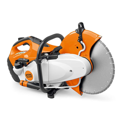
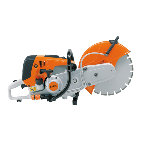
Stihl TS 440 User manual

2019-03
STIHL TS 440 Service Manual


Printed on chlorine-free paper
Printing inks contain vegetable oils, paper can be
recycled.
© ANDREAS STIHL AG & Co. KG, 2019
RA_021_2015_01_01. VA3.C19.
0000007243_007_GB
TS 440 1
This service manual is protected by copyright. All rights reserved, especially the rights to reproduce, translate and process with electronic
systems.
Contents
1 About this Service Manual 2
1.1 Applicable Documentation 2
1.2 Symbols in Text 2
2 Safety During Repair Work 2
2.1 Protective gloves 2
2.2 Safety goggles 2
2.3 Spare parts 2
2.4 Screws 2
3 Preparations for Repair 2
3.1 Preparing the cut-off machine 2
4 V-ribbed belt 3
4.1 Tools, aids 3
4.2 Removing the rear V belt 3
4.3 Installing the rear V belt 4
4.4 Removing the front V belt 5
4.5 Installing the front V belt 5
5 Clamping arms 7
5.1 Tools, aids 7
5.2 Removing the rear clamping arm 7
5.3 Installing the rear clamping arm 8
5.4 Removing the front clamping arm 8
5.5 Installing the front clamping arm 9
6 Belt pulleys 10
6.1 Tools, aids 10
6.2 Removing the middle belt pulley 10
6.3 Installing the middle belt pulley 10
6.4 Removing the front belt pulley 10
6.5 Installing the front belt pulley 11
7 Connecting piece with guard 12
7.1 Tools, aids 12
7.2 Removing the connector 12
7.3 Installing the connector 13
8 Brake band 14
8.1 Tools, aids 14
8.2 Removing the brake band 14
8.3 Installing the brake band 15
9 Brake lever 16
9.1 Tools, aids 16
9.2 Removing and dismantling the brake lever 16
9.3 Assembling and installing the brake lever 17
10 Brake service 18
10.1 Interactive video tutorials 18
10.2 Tools, aids 18
10.3 Replacing the front belt pulley 18
10.4 Removing the connector, brake band and
brake lever 20
10.5 Installing new brake lever, new brake band
and new V belts 22
11 Fly wheel 27
11.1 Tools, aids 27
11.2 Removing the flywheel 27
11.3 Installing the flywheel 27
12 Generator 29
12.1 Tools, aids 29
12.2 Removing the generator 29
12.3 Installing the generator 30
13 Electromagnet 32
13.1 Tools, aids 32
13.2 Removing the electromagnet 32
13.3 Installing the electromagnet 33
14 Electronic Module 34
14.1 Tools, aids 34
14.2 Removing the electronic module 34
14.3 Installing the electronic module 35
15 Solenoid valve 36
15.1 Tools, aids 36
15.2 Removing the solenoid valve 36
15.3 Installing the solenoid valve 37
16 Control panel 38
16.1 Tools, aids 38
16.2 Removing the control panel 38
16.3 Installing the control panel 39
17 Cable routing 41
17.1 Tools, aids 41
17.2 Removing control panel – electronic module
wiring harness 41
17.3 Installing control panel – electronic module
wiring harness 42
18 Interactive Tutorials 44

TS 4402
1.1 Applicable Documentation
NPlease observe the following documentation in
addition to this service manual.
–Spare parts documentation
–TI bulletins
–Instruction manual
1.2 Symbols in Text
2.1 Protective gloves
Sharp or hot components can cut or burn people.
NIf sharp or hot components must be touched during
repair: Wear protective gloves.
2.2 Safety goggles
Objects can be hurled up at high speed during repair.
Objects thrown up can cause injury to the eyes.
NIf components can be thrown up during repair: Wear
safety glasses.
2.3 Spare parts
If spare parts which have not been approved by STIHL are
installed, the functions of components can no longer be
performed or safety devices can be deactivated. People
can be seriously injured or killed.
NSTIHL recommends the use of genuine STIHL spare
parts.
2.4 Screws
Thread forming screws
Screws with the designation P or DG press a permanent
thread into the material when screwed in. If the screw
does not engage in the existing thread when re-installed,
the safety of the screw connection can no longer be
guaranteed.
NIf screws with the designation P or DG are screwed
into an existing thread:
–Insert the screw into the hole.
–Turn the screw counterclockwise until the screw
slightly sinks into the hole.
The screw engages in the existing thread.
–Tighten the screw clockwise to the specified torque.
Micro-encapsulated screws:
The micro-encapsulated pre-coating is only effective
when the screw is first screwed in. If a microencapsulated
screw is reused, the screw connection may come loose
during operation.
NReplace micro-encapsulated screw.
NIf a micro-encapsulated screw is reused, perform the
following steps:
–Clean threaded hole and screw thread.
–Coat thread of screw with thread-locking adhesive.
–Tighten the screw to the specified torque.
Aluminum screws
NDo not reuse screws.
NScrew in the screws crosswise up to the head rest.
NTighten the screws crosswise.
NTurn the screws crosswise by 90°.
3.1 Preparing the cut-off machine
NEmpty fuel tank into a container suitable for fuel.
NRemove abrasive wheel.
NClean cut-off machine.
1 About this Service Manual
This symbol refers to a chapter in this service
manual.
A video is available for this chapter
This symbol shows the tightening torque for a
screw joint and the procedure after tightening.
In this example: Tightening torque 5 Nm. Then
rotate 1 full turn counterclockwise.
2 Safety During Repair Work
5 Nm
1
3 Preparations for Repair

TS 440 3
4.1 Tools, aids
–Socket T27x125 – 0812 542 2104 or equivalent tool
–Locking pin - 4130 893 7800
–Torque wrench – 5910 890 0302 or equivalent tool
–Torque wrench – 5910 890 0312 or equivalent tool
–Screwdriver T27x200 – 5910 890 2415 or equivalent
tool
–Socket 13 mm – 5910 893 5608 or equivalent tool
–Socket 19 mm, long – 5910 893 5613 or equivalent
tool
–13 mm box wrench, offset
–19 mm box wrench, offset
–Flex ratchet wrench
–Extension for flex ratchet wrench
4.2 Removing the rear V belt
NPrepare for repair, @ 3.1
NUndo screw (1).
NRemove guard (2).
NRemove screws (3).
NRemove “starter cover with rewind starter” (4).
NSlacken nut (8).
NTurn clamping arm (9) using hexagon (arrow)
counterclockwise as far as it will go and hold.
NTighten nut (8). The V belt (5) is relaxed.
4 V-ribbed belt
5
2
1
M5X21
(6 Nm / 53 lbf. in.)
4
0000-GXX-0430-A2
76
3M5x20 (6 Nm / 53 lbf. in.)
8
0000-GXX-0431-A0
9
5

TS 4404
NActuate the brake lever (7) and hold it there.
NPush locking pin (arrow) 4130 893 7800 through the
holding-down clamp (10) as far as it will go. The brake
lever underneath the holding-down clamp (10) will be
immobilized.
NRelease the brake lever (7).
NRemove the V belt (5).
NActuate the brake lever (7) and hold it there.
NRemove locking pin (arrow) 4130 893 7800.
NSlowly release brake lever (7).
4.3 Installing the rear V belt
NIf the front V belt (6) is removed: Install front V belt (6),
@ 4.5
NActuate the brake lever (7) and hold it there.
NPush locking pin (arrow) 4130 893 7800 through the
holding-down clamp (10) as far as it will go. The brake
lever underneath the holding-down clamp (10) will be
immobilized.
NRelease the brake lever (7).
NMount V belt (5) starting on the clutch drum.
NOnce the V belt is mounted, turn the front belt pulley
3 turns.
NSlowly undo the nut (8). The V belt (5) is tensioned.
NTurn the center belt pulley 3 turns. The tension is
evenly distributed.
10
5
7
0000-GXX-0935-A1
0000-GXX-0936-A1
5
7
8
10

TS 440 5
NCarry out a visual inspection. The profile of the V belt
lines up with the profile of the rear and center belt
pulley.
NTighten nut (8) (20 Nm / 177 lbf. in.).
NActuate the brake lever (7) and hold it there.
NRemove locking pin (arrow) 4130 893 7800.
NSlowly release brake lever (7).
NPlace “starter cover with rewind starter” (4) in
position.
NInsert screws (3) and tighten.
NPlace guard (2) in position.
NInsert screw (1) and tighten.
4.4 Removing the front V belt
NPrepare for repair, @ 3.1
NRemove guard (2), @ 4.2.
NRemove “starter cover with rewind starter” (4), @ 4.2.
NRemove the rear V belt (5), @ 4.2.
NSlacken nut (12).
NTurn clamping arm (11) using hexagon (arrow)
counterclockwise as far as it will go and hold.
NTighten nut (12). The V belt is relaxed.
NRemove the V belt (6).
4.5 Installing the front V belt
NMount V belt (6) starting on the center pulley (arrow).
NOnce the V belt is mounted, turn the front belt pulley
3turns.
NSlowly undo the nut (12). The V belt (6) is tensioned.
NTurn the center belt pulley 3 turns. The tension is
evenly distributed.
12
11
0000-GXX-0432-A1
6
6
0000-GXX-0433-A0
12
6
0000-GXX-0937-A1
13

TS 4406
NCarry out a visual inspection. The profile of the V belt
lines up with the profile of the center and front belt
pulley.
NIf a new V belt is installed: Slide the “19 mm auxiliary
tool” (13) onto the hexagon and apply and hold a
torque of 10 Nm / 89 lbf. in. to the “19 mm auxiliary
tool” (13).
NTighten nut (12) (20 Nm / 177 lbf. in.).
NInstall the rear V belt (5), @ 4.3.
NAttach “starter cover with rewind starter” (4), @ 4.3.
NAttach guard (2), @ 4.3.

TS 440 7
5.1 Tools, aids
–Carburetor screwdriver – 0000 890 2300 or
equivalent tool
–Torque wrench – 5910 890 0312 or equivalent tool
–Socket 13 mm – 5910 893 5608 or equivalent tool
–Pliers, curved
–13 mm box wrench, offset
–Flat screwdriver 5.5 mm
–Flex ratchet wrench
–Extension for flex ratchet wrench
5.2 Removing the rear clamping arm
NPrepare for repair, @ 3.1
NRemove guard, @ 4.2.
NRemove “starter cover with rewind starter”, @ 4.2.
NRemove the rear V belt, @ 4.2.
NRemove E–clip (1).
NUndo nut (2). The clamping arm (3) snaps downward.
NPull off clamping arm (3) and remove torsion
spring (4).
5 Clamping arms
12
0000-GXX-0434-A2
8
7
6M8 (20 Nm / 177 lbf. in.)
4
3
2M8 (20 Nm /
177 lbf. in.)
9
5
111
D4x12 (3,5Nm /
31 lbf. in.)
M8 (20 Nm / 177 lbf. in.) 10
3
0000-GXX-0435-A1
4

TS 4408
5.3 Installing the rear clamping arm
NInsert torsion spring (4).
NHook pin (arrow) into torsion spring (4).
NSlide on clamping arm (3).
NScrew on nut (2).
NInstall E-clip (1).
NTurn clamping arm (3) by the hexagon
counterclockwise as far as it will go and hold.
NTighten nut (2).
NInstall the rear V belt, @ 4.3.
NInstall “starter cover with rewind starter”, @ 4.3.
NFit guard, @ 4.3.
5.4 Removing the front clamping arm
NPrepare for repair, @ 3.1
NRemove guard, @ 4.2.
NRemove “starter cover with rewind starter”, @ 4.2.
NRemove the rear V belt, @ 4.2.
NRemove the front V belt, @ 4.4.
NRemove the middle belt pulley, @ 6.2.
NUndo nut (10).
NRemove screws (11).
NRemove the holding-down clamp (12).
NPush tension rod (13) upward and hold it there.
NPush the brake lever (9) gently downward. The
tension rod (13) will detach from the brake lever (9).
NRemove E–clip (5).
NUndo nut (6).
NPull off clamping arm (7) and remove torsion
spring (8).
3
0000-GXX-1241-A0
4
13
9
0000-GXX-4833-A0
13
7
0000-GXX-0438-A1
8

TS 440 9
5.5 Installing the front clamping arm
NInsert torsion spring (8).
NHook pin (arrow) into torsion spring (8).
NSlide on clamping arm (7).
NScrew on nut (6).
NInstall E-clip (5).
NTurn clamping arm (7) by the hexagon
counterclockwise as far as it will go and hold.
NTighten nut (6).
NHook tension rod (13) onto the brake lever (9).
NPull brake lever (9) toward the handlebar. The
tension rod (13) engages.
NSlowly release brake lever (9).
NInsert holding-down clamp (12).
NInsert screws (11) and tighten.
NScrew on and tighten nut (10).
NInstall middle belt pulley, @ 6.3.
NInstall the front V belt, @ 4.5.
NInstall the rear V belt, @ 4.3
NInstall “starter cover with rewind starter”, @ 4.3.
NFit guard, @ 4.3.
7
0000-GXX-0439-A0
8
13
9
0000-GXX-4834-A0

TS 44010
6.1 Tools, aids
–Locking pin - 4130 893 7800
–Torque wrench – 5910 890 0312 or equivalent tool
–Socket 17 mm – 5910 893 5610 or equivalent tool
–17 mm box wrench, offset
–Flex ratchet wrench
–Extension for flex ratchet wrench
–Loctite 270 (thread-locking adhesive, high strength) –
0786 111 2109
6.2 Removing the middle belt pulley
NPrepare for repair, @ 3.1.
NRemove guard, @ 4.2.
NRemove “starter cover with rewind starter”, @ 4.2.
NRemove the rear V belt, @ 4.2.
NRemove the front V belt, @ 4.4.
NUnscrew the nut (1) (left-hand thread).
NRemove washer (2).
NPull off the belt pulley (3).
6.3 Installing the middle belt pulley
NPush on the belt pulley (3).
NSlide on the washer (2).
NScrew on and tighten nut (1) (left-hand thread).
NInstall the front V belt, @ 4.5.
NInstall the rear V belt, @ 4.3.
NInstall “starter cover with rewind starter”, @ 4.3.
NFit guard, @ 4.3.
6.4 Removing the front belt pulley
NPrepare for repair, @ 3.1.
NRemove the rear V belt, @ 4.2.
NRemove the front V belt, @ 4.4.
NBlock belt pulley (6) with locking pin (arrow)
4130 893 7800.
NUnscrew the nut (4) (left-hand thread).
NRemove washer (5).
6 Belt pulleys
0000-GXX-0441-A2
1M10x1L (40 Nm / 354 lbf. in.)
3
2
5
6
4M10x1L (40 Nm / 354 lbf. in.)
0000-GXX-0442-A0
4
6
5

TS 440 11
NRemove locking pin (arrow) 4130 893 7800.
NPull off the belt pulley (6).
6.5 Installing the front belt pulley
NPush on the belt pulley (6).
NBlock belt pulley (6) with locking pin (arrow)
4130 893 7800.
NSlide on the washer (5).
NScrew on and tighten nut (4) (40 Nm / 354 lbf. in.) for
pre-tensioning (left-hand thread).
NUnscrew the nut (4) (left-hand thread).
NCoat thread of the shaft with thread-locking adhesive.
NScrew on and tighten nut (4) (40 Nm / 354 lbf. in.)
(Left-hand thread)
NRemove locking pin (arrow) 4130 893 7800.
NInstall the front V belt, @ 4.5.
NInstall the rear V belt, @ 4.3.
NAttach starter cover with rewind starter, @ 4.3.
NFit guard, @ 4.3.
0000-GXX-0443-A0
6
54

TS 44012
7.1 Tools, aids
–Socket T27x125 – 0812 542 2104 or equivalent tool
–Locking pin - 4130 893 7800
–Torque wrench – 5910 890 0302 or equivalent tool
–Torque wrench – 5910 890 0312 or equivalent tool
–Screwdriver T27x200 – 5910 890 2415 or equivalent
tool
–Socket 13 mm – 5910 893 5608 or equivalent tool
–Flat nosed pliers
–13 mm box wrench, offset
–Flat screwdriver 5.5 mm
–Flex ratchet wrench
–Extension for flex ratchet wrench
7.2 Removing the connector
NPrepare for repair, @ 3.1
NRemove guard, @ 4.2.
NRemove “starter cover with rewind starter”, @ 4.2.
NRemove the rear V belt, @ 4.2.
NRelease hose clip (1) on water connector.
NPull off hose (2) and hose clip (1).
NUndo screw (3).
NRelease cover (4) at the tab (arrow) and remove it.
NPull out white plug (8).
NPull grommet (9) out of the support (arrow)
NUndo the nuts (5).
NActuate the brake lever (6) and hold it there.
7 Connecting piece with guard
7
0000-GXX-0446-A2
1
4
2
5M8 (20 Nm / 177 lbf. in.)
3
P6x19 (6 Nm / 53 lbf. in.)
6
0000-GXX-0456-A1
4
0000-GXX-0457-A1
9
8

TS 440 13
NRemove connector (7) and attached parts.
NSlowly release brake lever (6).
7.3 Installing the connector
NActuate the brake lever (6) and hold it.
NPush locking pin (10) 4130 893 7800 through the
holding-down clamp (11) as far as it will go. The brake
lever underneath the holding-down clamp (11) will be
immobilized.
NRelease the brake lever (6).
NPlace connector (7) and attached parts in position
against the clutch drum and push on over the studs.
NScrew on nuts (5).
NActuate the brake lever (6) and hold it there.
NRemove locking pin (10) 4130 893 7800.
NSlowly release brake lever (6).
NPush the grommet (9) into the support (arrow).
NPlug white plug (8) into electronic module. The
plug (8) engages.
NFit cover (4). The cover (4) audibly engages.
NInsert screw (3) and tighten.
NPush hose (2) and hose clip (1) onto water
connection.
NClose hose clip (1).
NInstall the rear V belt, @ 4.3.
NInstall “starter cover with rewind starter”, @ 4.3.
NFit guard, @ 4.3.
6
10
0000-GXX-4836-A0
7
11
0000-GXX-0457-A1
9
8

TS 44014
8.1 Tools, aids
–Carburetor screwdriver – 0000 890 2300 or
equivalent tool
–Socket T27x125 – 0812 542 2104 or equivalent tool
–Torque wrench – 5910 890 0302 or equivalent tool
–Screwdriver T27x200 – 5910 890 2415 or equivalent
tool
–Loctite 242 (thread-locking adhesive, medium
strength) – 0786 111 2101
8.2 Removing the brake band
NPrepare for repair, @ 3.1
NRemove guard, @ 4.2.
NRemove “starter cover with rewind starter”, @ 4.2.
NRemove the rear V belt, @ 4.2.
NRemove connector, @ 7.2.
NRemove screws (1).
NRemove the holding-down clamp (2).
NUndo screw (3).
NPry brake band (4) out of the support (arrow).
NActuate the brake lever (5) and hold it there.
NLift brake band (4) out of guide.
NDetach brake band (4) from lever (6) and remove it.
NSlowly release brake lever (5).
8 Brake band
0000-GXX-0447-A2
4
5
2
M4x12 (3 Nm / 26 lbf. in.) 3
1D4x12
(3,5 Nm / 31 lbf. in.)
0000-GXX-0471-A0
4
0000-GXX-0472-A1
4
6

TS 440 15
8.3 Installing the brake band
NActuate the brake lever (5) and hold it there.
NHook brake band (4) onto the lever (6).
NInsert brake band (4) into guide (arrow).
NSlowly release brake lever (5).
NInsert brake band (4) and press it into the
support (arrow).
NCoat thread of screw (3) with thread-locking
adhesive.
NInsert screw (3) and tighten.
NInsert holding-down clamp (2).
NInsert screws (1) and tighten.
NInstall connector, @ 7.3.
NInstall the rear V belt, @ 4.3.
NInstall “starter cover with rewind starter”, @ 4.3.
NFit guard, @ 4.3.
0000-GXX-0473-A1
4
6
0000-GXX-0474-A0
4

TS 44016
9.1 Tools, aids
–Carburetor screwdriver – 0000 890 2300 or
equivalent tool
–Assembly tube – 1117 890 0900
–Assembly hook – 5910 890 2800
–Pliers, curved
–STIHL multi-purpose grease – 0781 120 1110
9.2 Removing and dismantling the brake lever
NPreparing for repair, @ 3.1.
NRemove guard, @ 4.2
NRemove “starter cover with rewind starter”, @ 4.2.
NRemove rear ribbed V-belt, @ 4.2.
NRemove rear clamping arm, @ 5.2.
NRemove connector, @ 7.2.
NRemove brake band, @ 8.2.
NUse assembly hook (6) 5910 890 2800 to detach the
tension spring (1) and remove it.
NPush brake lever (3) upward and hold it there.
NUnhook tension rod (7).
NPush brake lever (3) downward.
9Brake lever
0000-GXX-0448-A1
4
1
4
5
3
2
0000-GXX-0893-A0
1 6
0000-GXX-0894-A1
37

TS 440 17
NRemove E-clips (4).
NPull off brake lever (3) and lever (5).
NRemove lever (5) from brake lever (3).
9.3 Assembling and installing the brake lever
NClean lever (5), brake lever (3) and installation site.
NGrease pins (9, 10) including the surfaces in the area
around the brake lever (3).
NInsert lever (5) into brake lever (3).
NPush brake lever (3) and lever (5) onto the pins on the
connector.
NFit the E-clips (4).
NGrease area around the lever (arrows). Total quantity
of grease: 10 g (0.4 oz.).
NPush brake lever (3) upward and hold it there.
NHook in the tension rod (7).
NPush brake lever (3) downward.
NHook tension spring (1) into the lever (5) and push it
over the pin (arrow) with the aid of the assembly
tube (8) 1117 890 0900.
NInstall brake band, @ 8.3.
NInstall connector, @ 7.3.
NInstall rear clamping arm, @ 5.3.
NInstall rear ribbed V-belt, @ 4.3.
NInstall “starter cover with rewind starter”, @ 4.3.
NFit guard, @ 4.3.
0000-GXX-4313-A0
9
10
0000-GXX-0895-A1
35
0000-GXX-4314-A0
0000-GXX-0896-A1
3
7
1
8
5

TS 44018
10.1 Interactive video tutorials
10.2 Tools, aids
–Carburetor screwdriver – 0000 890 2300 or
equivalent tool
–Socket T27x125 – 0812 542 2104 or equivalent tool
–Assembly tube - 1117 890 0900
–Locking pin - 4130 893 7800
–Torque wrench – 5910 890 0302 or equivalent tool
–Torque wrench – 5910 890 0312 or equivalent tool
–Screwdriver T27x200 – 5910 890 2415 or equivalent
tool
–Assembly hook - 5910 890 2800
–Socket 13 mm – 5910 893 5608 or equivalent tool
–Socket 19 mm, long – 5910 893 5613 or equivalent
tool
–Pliers, curved
–Flat nosed pliers
–13 mm box wrench, offset
–19 mm box wrench, offset
–Flat screwdriver 5.5 mm
–Sidecutters
–Flex ratchet wrench
–Extension for flex ratchet wrench
–Loctite 242 (thread-locking adhesive, medium
strength) – 0786 111 2101
–Loctite 270 (thread-locking adhesive, high strength) –
0786 111 2109
10.3 Replacing the front belt pulley
10.3.1 Removing the front belt pulley
NPrepare for repair, @ 3.1.
NUndo screw (1).
NRemove guard (2).
NRemove screws (3).
NRemove “starter cover with rewind starter” (4).
NCut through both V belts (5, 6) and remove.
10 Brake service
5
2
1
M5X21
(6 Nm / 53 lbf. in.)
4
0000-GXX-0430-A2
76
3M5x20 (6 Nm / 53 lbf. in.)
Interactive video tutorial “Carrying Out a Brake
Service”.
Other manuals for TS 440
3
Table of contents
Other Stihl Saw manuals

Stihl
Stihl 2016-07 User manual

Stihl
Stihl TS 700 User manual

Stihl
Stihl MS 260 User manual

Stihl
Stihl TS 400 Cutquick User manual

Stihl
Stihl Cutquik TS 410 User manual

Stihl
Stihl TSA 230 User manual

Stihl
Stihl TSA 230 User manual

Stihl
Stihl TS 700, TS 800 User manual

Stihl
Stihl Cutquik TS 700 User manual

Stihl
Stihl MS 18 Building instructions