Stinger HEIGH10 UN1810E-VX1 User manual

Copyright © 2023 StingerElectronics-EU.com
INTEGRATED INFOTAINMENT TOUCH SCREEN SOLUTION FOR
VAUXHALL ASTRA J 2009 - 2016
PART NUMBER: UN1810E-VX1
INSTALLATION GUIDE

2
www.sngerelectronics-eu.com
ABOUT THIS PRODUCT
Upgrade your Vauxhall Astra’s radio with the HEIGH10® 10-inch infotainment system. Retain all OEM features, vehicle
sengs, and more. All in one easy to install, plug-and-play package.
The HEIGH10® is designed to enhance screen size and infotainment features for drivers which include Apple CarPlay,
Android Auto, DAB+, and Bluetooth streaming. Paired with the vehicle retenon interface, key vehicle sengs will be
retained and controlled through the HEIGH10® display by your steering wheel controls.
The components of this kit are compable for the Vauxhall Astra J 2009 - 2016.
Please note: Not compable for models with navigaon systems / amplied systems.
CONTENTS
• HEIGH10® unit with ng accessories and wiring
• Black double DIN fascia plate (with accessories)
• Vehicle retenon interface with plug-and-play harness
• Vehicle specic antenna adapter (AM/FM)
• Snger stereo patch lead
• Instrucon manual

3
www.sngerelectronics-eu.com
FITTING GUIDE
STEREO REMOVAL

4
www.sngerelectronics-eu.com
FITTING GUIDE
Take the HEIGH10® components and begin to assemble the core components in accordance with the “Installaon
Manual” that comes with unit.
HEIGH10 ASSEMBLY
STEREO REMOVAL
Once the radio is removed, you will be required
to transfer the climate controls and other various
buons as indicated by the photo to the new fascia
panel.
1. Li up the gear sck cover and remove the two screws
from either side of the frame.
2. Give the fascia a rm pull in order to release the clips.
3. Li up the tabs under the heater vents in order to reveal
two addional screws and remove these.
4. This will allow removal of the control panel, You will
nd several connecons aached that will need to be
removed.
5. Remove the 4 bolts securing the radio’s main unit to the
vehicle.
6. Unplug the connecons on the rear.

5
www.sngerelectronics-eu.com
FITTING GUIDE
INTERFACE SET-UP
FASCIA PLATE SET-UP
1. With the HEIGH10® unit congured correctly, aach the fascia brackets to the relevant sides of the radio module
using the screws within the kit. Place into the vehicle and roughly test t with the fascia to measure whether the
brackets need moving forwards/backwards.
2. With the brackets aligned correctly, aach the fascia to the brackets over the top of the unit using the screws that
come within in the kit.
3. Once all of the steps in ‘Stereo Installaon’ are complete, place the assembly into the dashboard and screw down
using the pre-exisng screws. Then reassemble the main fascia panel.
4. Aach the antenna adapter to the vehicles pre-exisng connecon and the back of new HEIGH10® unit.
1. Take the 14-way connector on the vehicle interface harness and plug this into the relevant connecon on the side
of the interface.
2. Take the 12-way connector of the stereo patch lead and plug this into the relevant connecon on the side of the
interface. Then take the 3.5mm jack and aach this to the HEIGH10® unit.
3. Aach the 4-way camera extension harness to the interface.
5. Aach the USB retenon lead in between the vehicle pre-exisng USB connector and the HEIGH10® unit.
6. Connect the male yellow RCA to the ‘reverse camera input’ on the back of the new stereo.
8. Aach the addional wiring on the harness to the back of the stereo:
Pink - Speed Pulse Green - Park Brake Purple - Reverse
9. When all the above wires (and any addional accessories) have been connected, nally make the power connec-
ons between the stereo and the vehicles pre-exisng connector.
For a full connecon breakdown of the HEIGH10® unit, see the “Installaon Manual” that comes with the unit.
7. Connect the aermarket reverse camera (if required) to the female yellow RCA on the camera extension harness.
Note: ensure the ‘Camera Connected’ opon in the ‘Preferences’ menu is set to ‘Yes’ for the camera to funcon cor-
rectly.

6
www.sngerelectronics-eu.com
ABOUT THIS PRODUCT
CTHVX01
CAN-Bus Steering Wheel Control Interface with built-in speaker for Vauxhall/Opel vehicles. Retains
vehicle settings menu, vehicle chimes and OEM phone buttons (if equipped)
Read the manual prior to installation. Technical knowledge is necessary for installation. The place of
installation must be free of moisture and away from heat sources. Please ensure that the correct tools are using
during the installation to avoid damage to the vehicle or product. Connects2 can not be held responsible for
the installation of this product.
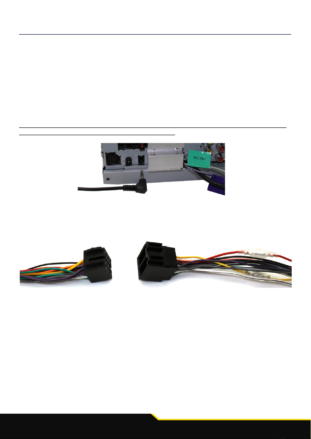
WIRING COLOUR CODES
Purple Right Rear Speaker +
Purple/Black Right Rear Speaker -
Green Left Rear Speaker +
Green/Black Left Rear Speaker -
Grey Right Front Speaker +
Grey/Black Right Front Speaker -
White Left Front Speaker +
White/Black Left Front Speaker -
Yellow Permanent 12V
Black Ground
Red Ignition 12V
Pink Speed Pulse
Purple/WhiteReverse Gear
Green Park Brake
Yellow/BlackTelephone Mute
Blue/White Antenna Remote
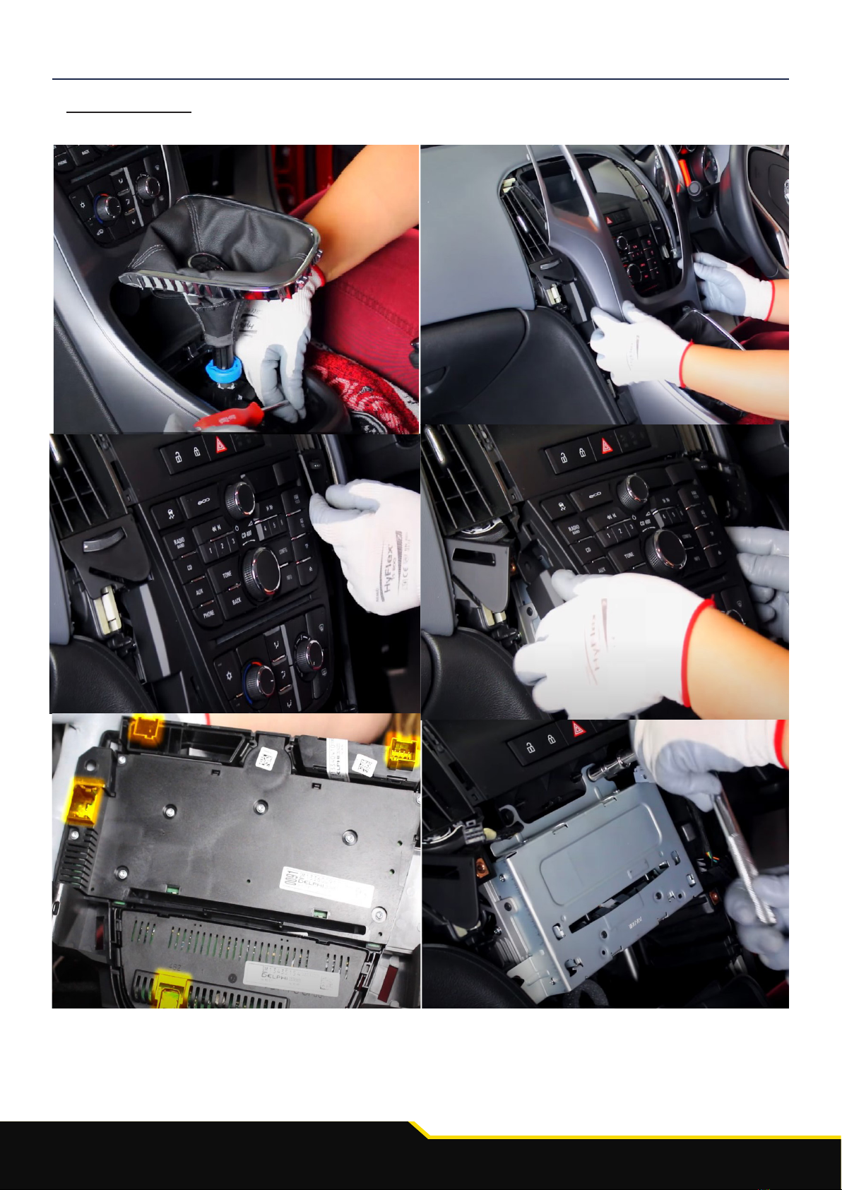
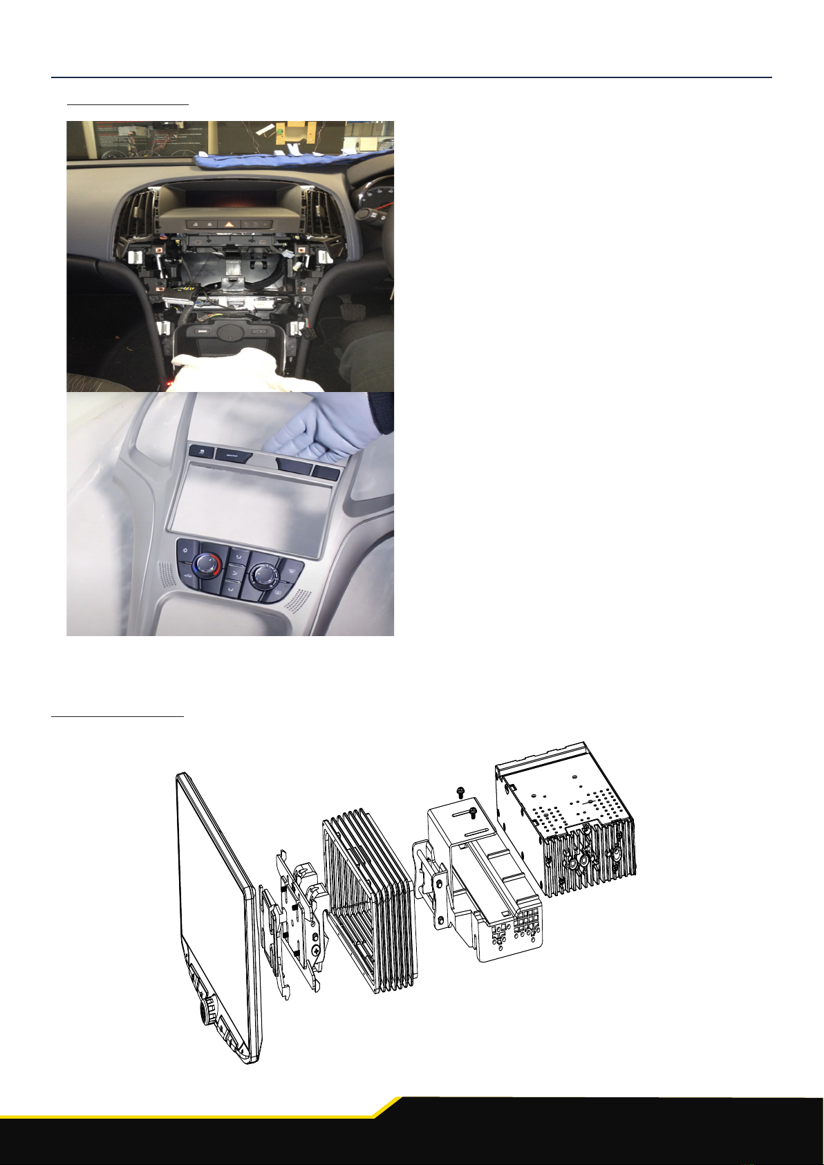
PRIOR TO INSTALLATION
SETTING THE DIPSWITCHES
Before installation, make sure that the dipswitches on the interface are set according to the
below information:
Set Dipswitch 1 to ‘On’ if installing a Pioneer aftermarket stereo, and ‘Off’ if installing a Sony
aftermarket stereo. If installing any other brand of stereo, Dipswitch 1 can be set to any posi-
tion
Set Dipswitch 2 to ‘On’ if installing the product into a vehicle with 2 Line Display, and ‘Off’ if
installing into a vehicle with 4 Line Display
Dipswitches 3 & 4 have no functionality with this product and can be left in their default posi-
tions
For Installation into Vauxhall Meriva Vehicles
If steering wheel control functions are unresponsive after installation, press the
‘Track Down’ repeatedly 8 times until an audible beep is heard. This conrms the
interface has switched to the Meriva protocol. To reverse this back to non Meriva
protocol, repeat the process above.
!

7
www.sngerelectronics-eu.com
FITTING GUIDE
1. Remove and disconnect the original head unit.
2. Connect the 12 way molex connector of the head unit patch lead (supplied
separately) to the interface.
3. Connect the opposite end of head unit patch lead to the head unit steering
wheel control input on the back of the aftermarket head unit.
NB: This may be a 3.5mm jack plug or a wire input depending upon the head unit brand be-
ing tted. Please see the head unit installation manual for further information on
where to connect.
Important: This step must be completed before connecting power to the interface. Failure to
so do may result in no steering wheel control function.
4. Connect the 14 way molex connector to the interface
5. Connect the male power/speaker ISO harness to the female power/speaker ISO harness
from the aftermarket head unit. For aftermarket head units without an ISO
connector, please refer to “Wiring Colour Codes” on Pg. 2.
6. Connect the female vehicle specic connectors on the harness to the male vehicle con-
nector from the vehicle. Test head unit for correct operation.

8
www.sngerelectronics-eu.com
STEERING WHEEL CONTROL FUNCTIONALITY
Function
Volume +
Volume -
Track +
Track -
Source (Short Press)
Enter Settings Menu (Long Press)
Pick Up
Hang Up
Original Button
Volume +
Volume -
Up Arrow
Down Arrow
SRC
SRC
Pick Up/Speech
Mute/Hang Up
Navigating the Settings Menu
1. Long press “SRC” to enter Settings Menu.
2. Use “Up Arrow” and “Down Arrow” to scroll through the menu options.
3. Short Press “SRC” to enter a sub-menu.
4. Short Press “SRC” to select the desired option.
5. Press “Mute/Hang Up” to go back.

9
www.sngerelectronics-eu.com
For further help or assistance, please contact and ll out a support cket with full details of your issue via :
uktechnic[email protected]
For general enquires, contact us at:
Phone: 01384 958 500
E-Mail: snger[email protected]
Mon - Fri 9am - 5.30pm GMT
TECHNICAL ASSISTANCE
If you would like to download a digital copy of this manual, or any other product, then please visit the www.Snger-
Electronics-EU.com website.
This manual is considered correct at the me of prinng but is subject to change. For the latest manuals & updates,
refer to our website.
Copyright 2023 by Snger.
AGREEMENT: End user agrees to use this product in compliance with the instrucons and terms of use and with all laws.
STINGER provides instrucons and safety warnings with respect to this product and disclaims all liability for any use not in
conjuncon with those instrucons or other misuse of its product. If you do not agree, please disconnue use and contact
STINGER. This product is intended for o-road use and passenger use only.
Table of contents
Other Stinger Automobile Accessories manuals

Stinger
Stinger STXKBR4 User manual

Stinger
Stinger SPXULED User manual

Stinger
Stinger XL 112 Supplement

Stinger
Stinger Heigh10 User manual

Stinger
Stinger STXJLPOD User manual

Stinger
Stinger HEIGH10 SRK-JK11H User manual

Stinger
Stinger XLINK XFDB108 User manual

Stinger
Stinger SR-RUN10H User manual

Stinger
Stinger VIP User manual

Stinger
Stinger DSI computer User manual
Popular Automobile Accessories manuals by other brands

Thule
Thule 1360 Fitting instructions

Steinhof
Steinhof H-050 FITTING AND OPERATION MANUAL

Alexo Sweden
Alexo Sweden ATS 624-0600 Installation and operating instructions

Toyota
Toyota PZ 416 - T0968 - 00 installation manual

Astro Pneumatic Tool
Astro Pneumatic Tool 7445 manual

ICINTRACOM
ICINTRACOM BT MIRROR KIT user guide