6
www.sngerelectronics-eu.com
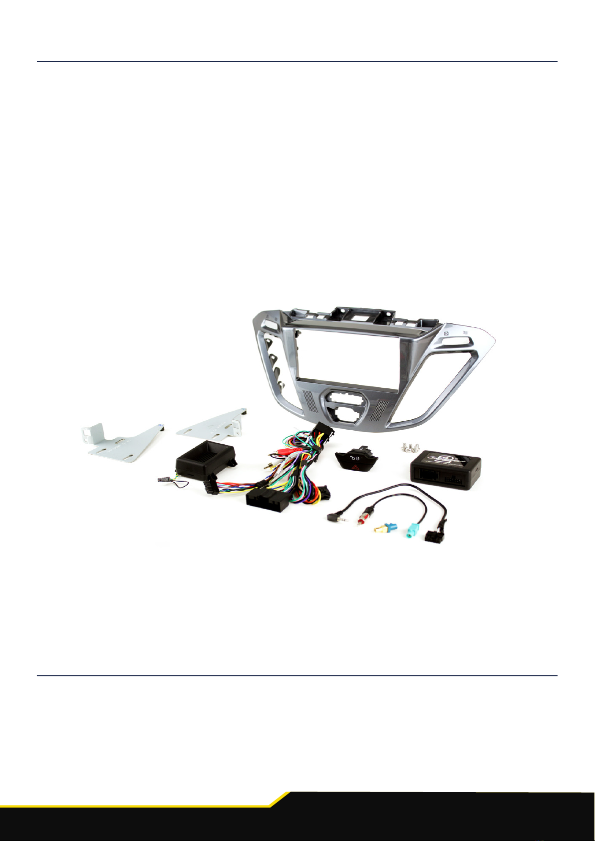
ABOUT THIS PRODUCT
CTSFO008.2
CAN-Bus Steering Wheel Control Interface for Ford vehicles. Retains steering wheel controls, park-
ing sensor audio and allows time/date change from the steering wheel.
Read the manual prior to installation. Technical knowledge is necessary for installation. The place of
installation must be free of moisture and away from heat sources. Please ensure that the correct tools are using
during the installation to avoid damage to the vehicle or product. Connects2 can not be held responsible for
the installation of this product.
WIRING COLOUR CODES
Purple Right Rear Speaker +
Purple/Black Right Rear Speaker -
Green Left Rear Speaker +
Green/Black Left Rear Speaker -
Grey Right Front Speaker +
Grey/Black Right Front Speaker -
White Left Front Speaker +
White/Black Left Front Speaker -
Yellow Permanent 12V
Black Ground
Red Ignition 12V
Orange Illumination
Green Park Brake
Pink Speed Pulse
Purple/White Reverse Gear
Blue/White Antenna Remote
PRIOR TO INSTALLATION
1. Remove and disconnect the original head unit.
2. Connect the 12 way molex connector of the head unit patch lead (supplied
separately) to the interface.
3. Connect the opposite end of head unit patch lead to the head unit steering
wheel control input on the back of the aftermarket head unit.
NB: This may be a 3.5mm jack plug or a wire input depending upon the head unit brand be-
ing tted. Please see the head unit installation manual for further information on
where to connect.
Important: This step must be completed before connecting power to the interface. Failure to
so do may result in no steering wheel control function.