STL Rear Raptor Series Supplement

2809 Business Park Dr • Buda • TX • 78610
Phone
800.757.2581 •
Fax
844.894.2652 •
Email
SpeedTech Lights, Inc © 2018
STL Rear Raptor® Series Interior LED Visor Light Bar
Operation Manual and Instructions
Congratulations, you are the owner of a STL Rear Raptor® Series Interior LED Visor Light Bar! Your bar is equipped with the latest technology and
features at the best value found industry wide, GUARANTEED. In addition to that, your purchase comes with the STL 5 Year Warranty against any
manufacturer defects that may occur with your bar. So please read this document carefully and call Customer Service at 800-757-2581 Monday -
Friday 8:30 AM - 4:30 PM central time if you need assistance. We are available and happy to help!
Warnings and Notices for Users and Installers
This document must be delivered to and read by the end user and installer as it serves to provide you with the required information for proper and
safe use of your STL product. Before operating this or any STL products the user and installer must read this manual all the way through. You will
nd important information in this manual that could prevent property damage and/or serious injury to the user and installer.
STL products are intended to alert pedestrians and other operators of the presence of personnel, the operation of emergency vehicles, an emer-
gency site, and any warning needs. This does not ensure that pedestrians or drivers will react, heed, or observe emergency warning signals. Nor
does the use of emergency signals grant or ensure you the right of way. It is your responsibility to make sure you can proceed safely before driving
against trac, entering an intersection, responding at a high rate of speed, or walking on or around trac lanes.
Your STL emergency vehicle devices should be tested daily to ensure the device and all its functions are operating correctly. If you experience a
malfunction contact STL’s Customer Service immediately for troubleshooting options, or a warranty or service claim. You must ensure sure that
the projection of the visual and audible signal is not blocked by vehicle components (i.e.: open trunks, visors, compartment doors), vehicles, other
obstructions, or people.
This is professional grade equipment and is intended for strict use by authorized personnel only. It is the user’s responsibility to understand and
obey all laws regarding emergency warning devices. You must know and be familiar with all applicable city, state, and federal laws and regulations
prior to the use of emergency vehicle warning devices.
SpeedTech Lights, Inc. assumes no liability for any loss resulting from the use of this warning device. Proper installation is vital to the performance
of the warning devices and safe operation of the emergency vehicle. Since the operator is under stressful environments the equipment must be
properly wired and mounted to ensure eectiveness and safety. Therefore controllers must be properly installed and placed within convenient
reach of the operator so eye contact with the roadway is never lost.
The eectiveness of your STL equipment is highly dependent upon correct mounting and wiring. Improper wiring and mounting of the warning
device will reduce the output and performance of the equipment. Emergency warning devices frequently require high electrical voltages and/
or currents. Properly protect and use caution around live electrical connections. Grounding or shorting of electrical connections can cause high
current arcing, which can cause severe personal injury and/or serious vehicle damage, including re.
Electromagnetic interference can be caused by many electronic devices used in emergency vehicles. To ensure that this doesn’t happen to you,
lightbars should be mounted a minimum of 12”- 34”from the radio antenna and do not power your equipment from the same circuit or share the
same grounding circuit with radio communication equipment. After installation, test all the vehicle’s equipment together to ensure everything
operates free of interference.
Driver and/or passenger airbags bags (SRS) will impact the way you mount your equipment. Any equipment installed in the deployment area of
the airbags will damage or dislodge the airbags and sensors. This will also reduce the eectiveness of the airbags to protect the passengers and
therefore these areas must be avoided. Installers must make sure that this equipment along with any parts, hardware, wiring, power supplies, and
switch boxes do not interfere with the airbags, SRS wiring, or sensors.

SpeedTech Lights, Inc © 2018
REAR RAPTOR® SERIES
All STL equipment needs to be mounted and installed according to the vehicle manufacturer’s instructions and securely attached to a part of the
vehicle of sucient strength to withstand the forces applied by the equipment. This device should be permanently mounted within the zones
specied by the vehicle manufacturer. This especially applies to equipment mounted on the exterior of the vehicle to avoid dislodging. Mount-
ing units on the interior of the vehicle by a method other than permanent mount is discouraged as it may become detached under aggressive
driving conditions such as sudden braking, collision, or swerving.
PROPER INSTALLATION COMBINED WITH OPERATOR TRAINING IN THE PROPER USE OF EMERGENCY
WARNING DEVICES IS ESSENTIALTO ENSURETHE SAFETY OF EMERGENCY PERSONNEL ANDTHE PUBLIC.
Important Points for Your Safety and Longevity of Your Light Bar
• Installers are required to have a good understanding of automotive electronic systems and procedures for proper installation.
• Never stare directly into the LEDs as momentary blindness and/or eye damage may occur.
• Never take any lights through a car wash. Use only water to clean the outer body/lens of your equipment.
• Never use a pressure washer to clean any STL products. Inspect and test your product daily to ensure it operates properly and is mounted
correctly.
• Never cut wires or work on a unit while the unit is still connected to a power source.
• Never install this product or route any wires through or in the deployment area of the airbag. Doing so may cause serious personal injury as
it will damage or reduce the eectiveness of the airbag by causing the unit to become a projectile. Reference the owner’s manual for your
vehicle to nd the airbag deployment area. The User/Installer assumes all responsibility to determine proper mounting location, based on
providing ultimate safety to all passengers in the vehicle.
• If the product requires you to drill holes, the installer must ensure that the drilling process does not damage any vehicle components or other
vital parts. Check all sides of the mounting surface before beginning to drill. Make sure to deburr all drilled holes and remove any metal rem-
nants or shards to avoid injury and wires from becoming spliced. Grommets are to be installed in all wire passage holes.
• In order for STL products to operate at optimum eciency, a secure and good electrical connection to the battery’s Ground Post must be
made. The recommended procedure requires the unit’s ground wire be connected directly to the NEGATIVE (-) battery post.
• Instruction manuals should be stored in a safe place for reference if you need to reinstall the unit or perform maintenance. They can also be
found at the main site under the product listing at www.SpeedTechLights.com. If your product is no longer available on the website contact
STL’s Customer Service at 800-757-2581 for assistance.
• If your product requires the use of a control box or remote device to turn on and control your equipment make sure it is installed in a location
that allows both the user and the vehicle to operate safely in any driving condition.
• Never activate or control your equipment in hazardous driving conditions.
• FAILURE TO FOLLOW THESE SAFETY PRECAUTIONS, WARNINGS, NOTICES, AND INSTRUCTIONS COULD RESULT IN DAMAGE TO THE PRODUCT
OR VEHICLE THAT WILL VOID YOUR WARRANTY AND/OR CAUSE SERIOUS INJURY TO YOU AND YOUR PASSENGER.
Unpacking Your STL Product
• Unpack your unit to identify all parts including but not limited to: Light Bar, switch box, brackets, screws, bolts, wiring harness, fuses, etc.
• Some parts may be in small bags.
• Some products may be packaged inside boxes of other products.
• Some parts such as Gutter Brackets, may be in the foam protection. Double check that no parts are left within the foam protection or left
in the box.
Pre-Installation and Testing
BENCH TEST all units prior to installation by connecting the Positive Cable (Red) and Negative Cable (Black) to a power source to ensure all the
features and parts of the Light Bar are functional.
Test Check List:
• All LEDs and LED Modules fully functional
• Flash patterns
• Non-volatile memory
• No physical damage
If you have trouble call Customer Service at 800-757-2581 before proceeding.
REAR RAPTOR® SERIES
SpeedTech Lights, Inc © 2018
Instructions for Mounting, Wiring and Programming
IMPORTANT! To ensure proper installation installers are required to have a good understanding of automotive electronic, systems and proce-
dures for proper installation. When you are drilling into the vehicle’s surfaces, ensure that the area is free of any electrical wires, vehicle uphol-
stery, fuel lines, etc. that could be damaged. All wiring passing through drilled holes should use grommets and silicone sealant to prevent wire
or moisture damage when passing through compartment walls. WARNING! Larger wires and secure or tight connections will ensure longer
service life for your product. It is highly recommended that soldered connections have heat shrink used to protect the connection. Special
attention should be given to the location and method of splicing wiresto make electrical connections to protect these splices from lost power
or connection and corrosion. Insulation displacement connectors are not to be used. To reduce voltage drop, minimize the number of splices in
the wires. The current carrying capacity of wires and fuses will be signicantly reduced under high ambient temperature (e.g. under the hood).
Use SXL type wire in the engine compartment where higher heat resistance is required according to SAE J-1128. All wires should be in accor-
dance with the minimum wire size and other recommendations made by the manufacturer and be protected from hot surfaces and moving
parts. Grommets, cable ties, looms, and other installation hardware should be used to anchor and protect all wiring. Fuses should be properly
sized and located as close to the power take o points as possible to protect the wiring and device. To protect against short circuits, a fuse is
included by STL for all products. Do NOT use a fuse with a higher amp rating than the initial fuse included. Do NOT use Circuit Breaks with STL
Products. Ground terminations should only be made directly to the battery.
Mounting Bracket:
• There will be two (2) pieces per side, each piece is identical to each other.
• Mount the side with the larger holes to your lightbar.
• Use the other side to mount the unit to the vehicle.
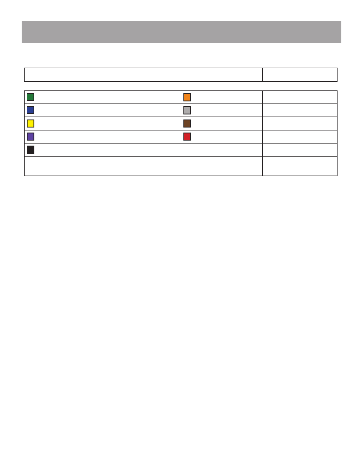
Wire Color Function Wire Color Function
Green Left Arrow Orange Center Out Arrow
Blue Right Arrow Grey Slow/Fast
Yellow Flash Pattern Brown Power
Purple Flash Mode *Red (Thick) Positive
*Black (Thick) Negative
*
Indicates a main power
cable
NOTE: All cables (except
Negative) contact +VDC

REAR RAPTOR® SERIES
SpeedTech Lights, Inc © 2018
How the STL Direct Control® Box Operates Your STL Light Bar
Power Switch
• Push this button to turn On/O the unit.
Flash Mode Button
• Switches back from Trac Advising mode to Warning mode.
Flash Pattern Button
• Button cycles to the next ash pattern with each press. Non-Volatile memory recalls the last ash pattern selected.
Left Button
• Toggles Left trac advisor pattern
Center Out Button
• Toggles Center Out trac advisor pattern
Right Button
• Toggles Right trac advisor pattern
Slow/Fast Slide Switch
• Toggles between Slow and Fast ashing speed
*Aux [Red (+) Positive] and Blue [(-) Negative wires]
• Rated for 10 AMPs
• 1st press: Power ON unit attached to aux cables
• 2nd press: Power OFF unit attached to aux cables
*These functions can be operated independently of the light bar’s warning lights being activated
Wiring: Connecting Wires to the Battery
WARNING! If you are supplying your own wiring that connects to the positive or negative terminal of the battery, fuse sizes must be sized according
to STL’s provided fuse to be considered fused properly to the battery in order to carry the load.
• Route the power cables by opening the wiring shield and running the cables through it towards your vehicle’s rewall.
• Follow the factory wiring harness through the rewall.
• If it is necessary to drill a hole in the rewall for the power cables, be sure no components will be damaged from drilling. As with all holes
that are drilled, le the edges down smooth and insert a grommet to protect the cables.
• Route the cable along the factory wiring harness towards the battery.
• Wire your power cables (Red with In Line Fuse (STL Supplied) and Black cable) to your battery to power up your Light Bar.
• You will want to ensure your grounding cable is taken directly to the negative terminal of your battery to avoid any electrical feedback which
may disrupt your Light Bar system.
• DO NOT allow the positive (Red wire) and negative (Black wire) to touch one another. This may cause injury to you and damage your equip-
ment by causing a short in the unit that is not covered under the STL warranty.

REAR RAPTOR® SERIES
SpeedTech Lights, Inc © 2018
Wiring: Connecting Wires to Control Box
• This unit will feature a power harness with eight (8) colored leads with a connector that plugs into the Direct Control® Box. When not utiliz
ing the Direct Control® Box reference the Wiring Diagram above.
• Now that you have pulled the cable into the vehicle attach the connector back to your Light Bar’s wire harness in the CORRECT positions
using a pin pusher and plug it into your Cigarette Lighter Plug. If you do not know the correct position of each wire in the connector call
customer service at 800-757-2581 before proceeding.
• If you did not purchase the Direct Control® Box and are using your own switch box , wire the cables accordingly into your control panel by
referencing the wiring diagram and instruction manual of your control panel.
•
Wiring: Connecting Extension Cables
• This unit will feature a power harness with eight (8) colored leads with a connector that plugs into the Direct Control® Box.
• If you have an extension cable with connectors, connect the corresponding ends to one another. Use the connector at the end of the cable
to plug into your control box.
• If you have an extension cable with one connector, you will need to cut the connector o of the main cable harness coming out of the Light
Bar. Save it as a spare part. You will solder, and heat shrink each wire within the cable harness to each wire in the extension cable harness.
DO NOT cross connect wires. Use the connector at the end of the extension cable to plug into your control box.
• If you have an extension cable with no connectors, you will need to cut in the middle of the main cable harness coming out of the Light
Bar. You will solder, and heat shrink each wire within the cable harness to each wire in the extension cable harness. DO NOT cross connect
wires. Use the connector at the end of the main cable harness to plug into your control box. DO NOT leave connectors, cables, solder points
exposed to heat or moisture or debris.
Programming Flash Patterns
• All STL LED products are equipped with a non-volatile memory which will recall the last ash pattern when the Light Bar is turned on.
• Set your ash pattern by pushing the Flash Pattern button on your Direct Control® Box to cycle through the various patterns until you nd
the appropriate pattern.
• If you are not using the Direct Control® Box you will follow the wiring diagram to identify the Flash Pattern wire to manually run through
and select the desired ash pattern.
Maintenance
While STL’s Light Bars are very durable, there are some things you need to keep in mind and practice to preserve the longevity and function of
your bar.
• Never take any STL Light Bars through a car wash, such as a pressure washer, automatic car wash, brushes that will scratch your equipment
or similar car washes or equipment where chemicals, high pressure water, and materials may scratch or damage your equipment.
• Use Water (H2O) with a soft cloth to clean your Light Bar and lenses.
• Yellowing of clear lenses may occur overtime. Lenses can be purchased by calling STL Customer Service at 800-757-2581.
All rights reserved. No part of this Operations Manual and Instructions may be reproduced, distributed, transmitted, or otherwise shared in any form or by any means, including but not limited to photocopying, recording,
electronic delivery, .pdf reproduction, or any other means of reproducing all or any part hereof without the express prior written consent of the SpeedTech Lights, Inc., except for non-commercial purposes as permitted
by United States copyright law. Customers of SpeedTech Lights, Inc., may download and print this Operations Manual and Instructions for use with products sold to the customer by SpeedTech Lights, Inc. However, no
part of the Operations Manual and Instructions may be otherwise or subsequently reproduced, downloaded, disseminated, published, or transferred, in any form or by any means, except with the prior written consent
of SpeedTech Lights, Inc.
Table of contents
Other STL Lighting Equipment manuals

STL
STL ALPHA 6x4 User manual

STL
STL K-FORCE SUPER TD 47 User manual

STL
STL M-TKFM14 User manual

STL
STL K-Force 27 Supplement

STL
STL Prime 55 Supplement

STL
STL K-FORCE MICRO 21 TIR User manual

STL
STL K-FORCE 47 User manual

STL
STL K-FORCE 55 User manual

STL
STL K-FORCE TOW 55 User manual

STL
STL M-LKFMMC21 User manual

STL
STL CEPTOR SUPER TD User manual

STL
STL ALPHA 7x9 User manual

STL
STL K-FORCE MICRO 21 User manual

STL
STL B-STC1 User manual

STL
STL STRIKER 8 User manual

STL
STL G-LZMC6 User manual

STL
STL VIRTUE 6 User manual

STL
STL K-FORCE 47 LINEAR User manual

STL
STL K-FORCE TOW 65 User manual

STL
STL K-Force Series Supplement


