GSB3-40, GSB3-60, GSB3-80
Glass wall touch controllers
EN
1/2
Characteristics /
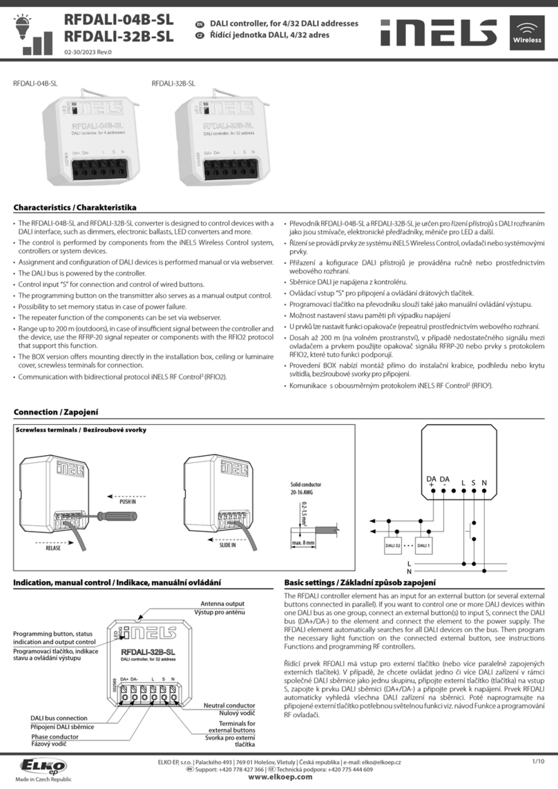
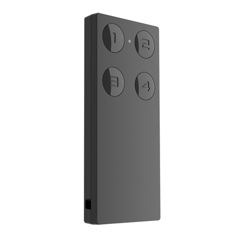
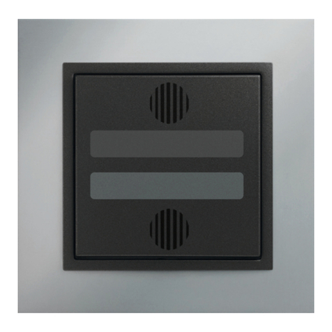
- The wall controller with touch controls series GSB3 is a design element (controller) in the system
iNELS with elegant and comfortable control. Controllers are available in black (e.g. GSB3-40/B)
and white (e.g. GSB3-40/W) variants.
- Between each pair of touch buttons there is available a pair of indicator LEDs (green, red) to
signal not only the status of the controlled appliances, but also the status of any sensor or actua-
tor in the system.
- At the location of each touch button there is available a blue diode signaling the touching of
the given button. Touching may be signaled by a vibration impulse or sound tone - selectable
in the software iDM3.
- Controllers are 4-channels (GSB3-80), 6-channels (GSB3-60) and 8-channels (GSB3-80).
- All versions are in the same dimension as a basic modular wall-switch (94x94 mm), in design
LOGUS90.
- Each controller is equipped with a thermo sensor. It is equipped with two analog-digital inputs
(AIN/DIN), and it is possible to connect two potentialless contact or an external temperature
sensor TC/TZ (for example on floor temperature measurement).
- Controllers are equipped with an ambient light intensity sensor. From the basic information
from the sensor, it is possible to illuminate orientation blue diodes in the touch controls GSB3
or perform various actions in the software iDM3, e.g. illuminate light circuits in a hallway, etc.
- Advantages over conventional switches / buttons include space saving, signaling of any output
system, the ability to measure temperature and also the ability to connect external buttons or
detectors.
- Each channel (button) can control any actuator (appliance) in the system. It is also possible to
program various functions or fuction macro (set of functions) to each button. This allows you to
control several appliances with one button simultaneously.
- Each button (channel) can have different functional modes beside lighting control:
a) Classic wall-switch: - upper button ON, bottom button OFF
b) Button controller (impulse relay): - first press ON, second press OFF
c) Dimmer: - short press – ON/OFF
d) Time switch: - ON after press, automatically OFF after set time
e) Setting light scenes – for example: for watching TV:
- shutters down
- main light 30% intensity
- wall-lamps 50% intensity.
- Design series LOGUS90 off ers glass frames in black and white color. These frames goes perfectly
with GSB3 wall buttons.
General instrucions /
CONNECTION TO THE SYSTEM, INSTALLATION BUS
iNELS3 peripheral units are connected to the system through the BUS installation. Installation BUS
conductors are connected to the terminal units to BUS+ and BUS- terminals, wires cannot be inter-
changed. For installation of BUS it is necessary to use a cable with a twisted pair of wires with a di-
ameter of at least 0.8 mm, the recommended cable is iNELS BUS Cable, whose features best meet
the requirements of the BUS installation. Bearing in mind that in terms of all the properties iit is it is
possible in most cases also use the cable JYSTY 1x2x0.8 or JYSTY 2x2x0.8, however it is not recom-
mended as the best option. In the case of a cable with two pairs of twisted wires it is not possible
to use the second pair of the other for modulated signal due to the speed of communications; it
is not possible within one cable to use one pair for one segment BUS and the second pair for the
second segment BUS. For installation of BUS it is vital to ensure that it is kept at a distance from the
power lines of at least 30 cm and must be installed in accordance with its mechanical properties.
To increase mechanical resistance of cables we recommend installation into a conduit of suitable
diameter. Topology installation of BUS is free except for a circle, each end of the BUS must termi-
nate at terminals BUS+ and BUS-. While maintaining all the above requirements, the maximum
length of one segment of the installation BUS can reach up to 550 m. Due to the data communica-
tion and supply of units in one pair of wires, it is necessary to keep in mind the diameter of wires
with regards to voltage loss on the lead and the maximum current drawn. The maximum length of
the BUS applies provided that they comply with the tolerance of the supply voltage.
CAPACITY AND CENTRAL UNIT
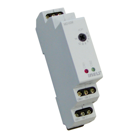
It is possible to connect to the central unit CU3-01M or CU3-02M two independent BUSes by
means of terminals BUS1+, BUS1- and BUS2+, BUS2-. It is possible to connect to each BUS up to
32 units, so it is possible to connect directly to the central unit a total of 64 units. It is necessary
to comply with the requirement of a maximum load of one BUS line - maximum up to 1000 mA
current. It is the sum of the rated currents of the units connected to the BUS line, other units can
be connected using the units MI3-02M, which generate further BUSes. These are connected to
the CU3 unit via the system BUS EBM and you can connect a total of 8 units via EBM BUS to the
central unit MI3-02M.
SUPPLYING THE SYSTEM
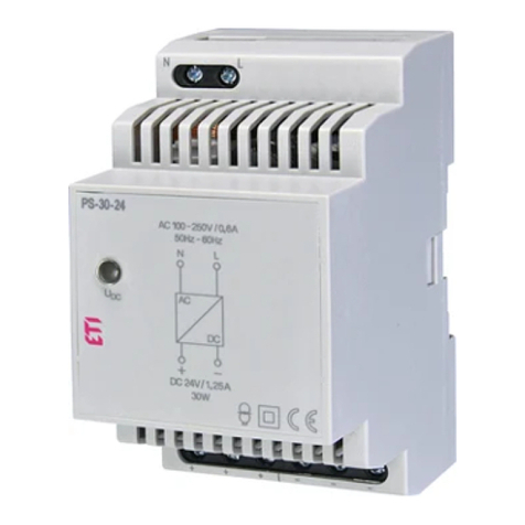
For supplying power to system units, it is recommended to use the power source of ELKO EP titled
PS3-100/iNELS. We recommend backing up the system with backup batteries connected to the
source of PS3-100/iNELS (see sample diagram of connecting the control system).
GENERAL INFORMATION
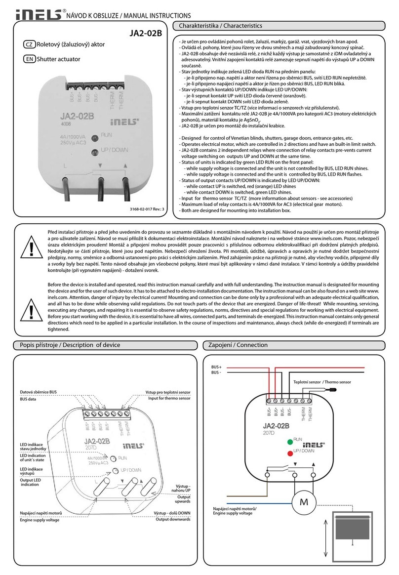
To operate the unit, it is necessary that the unit is connected to a central unit CU3 series, con-
nected to the central unit of the system CU3, or to a system that already contains this unit as its
expansion to include further system.
All unit parameters are set through the central unit CU3-01M in the software iDM3.
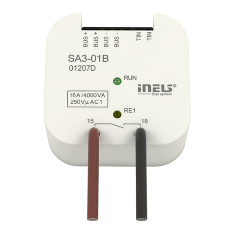
There is LED diode on the PCB for indication of supply voltage and communication with the cen-
tral unit series CU3. In case that the RUN diode flashes at regular intervals, so there is standard com-
munication between the unit and BUS. If the RUN diode lights permanently, so the unit is supplied
from BUS, but there is no communication between BUS and unit. In case that RUN diode is OFF, so
there is no supply voltage on the terminals BUS+ and BUS-.
SK Nástenné sklenené dotykové ovládače
Charakteristika
- Nástenné ovládače s dotykovým ovládaním rady GSB3 sú designovým prvkom (ovládačom) v
systéme iNELS s elegantným a príjemným ovládaním. K dispozícii sú ovládače v čiernej (napr.
GSB3-40/B) a bielej (napr. GSB3-40/W) variante.
- Medzi každou dvojicou dotykových tlačidiel je k dispozícii dvojica indikačných LED diód (zelená,
červená) pre signalizáciu stavu ovládaného spotrebiča, ale tiež stavu ľubovolného senzoru alebo
aktoru v systéme.
- V mieste každého dotykového tlačidla je k dispozícii modrá indikačná dióda signalizujúca dotyk
daného tlačidla. Dotyk môže byť ďalej signalizovaný vibračným impulzom alebo zvukovým tó-
nom - voliteľné v software iDM3.
- Ovládače sú dodávané ako štvorkanálové (GSB3-40), šesťkanálové (GSB3-60) a osemkanálové
(GSB3-80).
- Všetky varianty sú v rozmere základného modulu vypínača (94 x 94 mm) rady luxusných prístro-
jov LOGUS90.
- Každý ovládač je vybavený integrovaným teplotným senzorom. Ďalej je vybavený dvoma ana-
lógovými digitálnymi vstupmi (AIN/DIN), ktoré možno využiť pre pripojenie dvoch bezpoten-
ciálových kontaktov alebo jedného externého teplotného senzoru TC/TZ (napr. pre meranie
teploty podlahy).
- Ovládače sú vybavené senzorom intenzity vonkajšieho osvetlenia. Na základe informácií zo sen-
zoru možno rozsvecovať orientačné modré diódy v hmatníkoch GSB3 alebo vykonávať rôzne
akcie v software iDM3, napr. rozsvecovať svetelné okruhy na chodbe ai.
- Výhodou oproti štandardným tlačidlám / vypínačom je úspora miesta, signalizácia stavu ľubo-
volného výstupu systému, možnosť merať teplotu a tiež možnosť pripojenia externých tlačidiel
alebo detektorov.
- Každý kanál (tlačidlo) môže ovládať ktorýkoľvek aktor (spotrebič) v systéme. Ďalej je tiež možné
priradiť ku každému tlačidlu rôznu funkciu alebo makro (zostava funkcií). Je teda možné jedným
tlačidlom ovládať niekoľko spotrebičov zároveň.
- K
aždé tlačidlo (kanál) môže mať napríklad pri ovládaní osvetlenia priradené ďalšie funkčné režimy:
a) Klasický vypínač: horné tlačidlo zapnuté, spodné tlačidlo vypnuté
b) Tlačidlový ovládač (impulzné relé): jedným stlačením zapnuté, druhým stlačením vypnuté
c) Stmievač: krátke stlačenie - zapnúť/vypnúť,
d) Časový spínač: po stlačení zapnuté, po nastavenom čase automaticky vypne
e) Nastavenie svetelných scén - napr. na sledovanie TV :
- žalúzie zatiahnuť
- hlavné svetlo 30% intenzity
- lampičky na stenách 50% intenzity.
- V rámci dizajnovej rady LOGUS90 sú k dispozícii sklenené rámčeky v čiernom a bielom prevedení,
ktoré vhodne doplňujú ovládače rady GSB3.
Všeobecné inštrukcie
PRIPOJENIE DO SYSTÉMU, INŠTALAČNÁ ZBERNICA BUS
Periférne jednotky iNELS3 sa pripájajú do systému prostredníctvom inštalačnej zbernice BUS. Vo-
diče inštalačnej zbernice sa pripájajú na svorkovnice jednotiek na svorky BUS+ a BUS-, pričom
vodiče nie je možné zameniť. Pre inštalačnú zbernicu BUS je nutné využiť kábel s krúteným párom
vodičov s priemerom žíl najmenej 0.8 mm, pričom odporúčaným káblom je iNELS BUS Cable, kto-
rého vlastnosti najlepšie zodpovedajú požiadavkám inštalačnej zbernice BUS. S vedomím toho, že
sa z pohľadu všetkých vlastností nejedná o najlepšiu odporúčanú možnosť, je možné vo väčšine
prípadov využiť tiež kábel JYSTY 1x2x0.8 alebo JYSTY 2x2x0.8. V prípade káblu s dvoma pármi
krútených vodičov nie je možné vzhľadom k rýchlosti komunikácie využiť druhý pár pre iný modu-
lovaný signál, tedy nie je možné v rámci jedného káblu využiť jeden pár pre jeden segment BUS
zbernice a druhý pár pre druhý segment BUS zbernice. U inštalačnej zbernice BUS je nutné zaistiť
jeho odstup od silového vedenia vo vzdialenosti aspoň 30 cm a je nutné ho inštalovať v súlade s
jeho mechanickými vlastnosťami. Pre zvýšenie mechanickej odolnosti káblov odporúčame vždy
kábel inštalovať do elektroinštalačnej trubky vhodného priemeru. Topológia inštalačnej zbernice
BUS je voľná s výnimkou kruhu, pričom každý koniec zbernice je nutné zakončiť na svorkách BUS+
a BUS-. Pri dodržaní všetkých vyššie uvedených požiadaviek môže maximálna dĺžka jedného seg-
mentu inštalačnej zbernice dosahovať až 550 m. Z dôvodu, že dátová komunikácia i napájanie jed-
notiek sú vedené v jednom páre vodičov, je nutné dodržať priemer vodičov s ohľadom na úbytok
napätia na vedení a maximálny odoberaný prúd. Uvedená maximálna dĺžka zbernice BUS platí za
predpokladu, že sú dodržané tolerancie napájacieho napätia.
KAPACITA A CENTRÁLNA JEDNOTKA
K centrálnej jednotke CU3-01M alebo CU3-02M možno pripojiť dve samostatné zbernice BUS pro-
stredníctvom svoriek BUS1+, BUS1- a BUS2+, BUS2-. Na každú zbernicu možno pripojiť až 32 jed-
notiek, celkovo možno teda priamo k centrálnej jednotke pripojiť až 64 jednotiek. Ďalej je nutné
dodržať požiadavku na maximálne zaťaženie jednej vetvy zbernice BUS prúdom maximálne 1000
mA, ktorý je daný súčtom menovitých prúdov jednotiek pripojených na túto vetvu zbernice. V
prípade potreby je možné ďalšie jednotky pripojiť pomocou externých masterov MI3-02M, ktoré
generujú ďalšie dve vetvy BUS. Tieto externé mastery sa pripájajú k jednotke CU3 cez systémovú
zbernicu EBM a celkom je možné cez EBM zbernicu k centrálnej jednotke pripojiť až 8 jednotiek
MI3-02M.
NAPÁJANIE SYSTÉMU
K napájaniu jednotiek systému je možné použiť napájacie zdroje spoločnosti ELKO EP s názvom
PS3-100/iNELS. Odporúčame systém zálohovať externými akumulátormi, pripojenými ku zdroju
PS3-100/iNELS (pozri vzorovú schému zapojenia riadiaceho systému).
VŠEOBECNÉ INFORMÁCIE
Pre funkciu jednotky je nutné, aby bola napojená na centrálnu jednotku systému rady CU3, alebo
na systém, ktorý túto jednotku už obsahuje, ako jeho rozšírenie o ďalšie funkcie systému. Všetky
parametre jednotky sa nastavujú cez centrálnu jednotku rady CU3 v software iDM3.
Na prednom paneli jednotky je LED dióda RUN, ktorá indikuje napájacie napätie a komunikáciu s
centrálnou jednotkou rady CU3. V prípade, že dióda RUN bliká v pravidelnom intervale, prebieha
štandardná komunikácia. Ak dióda RUN trvale svieti, je jednotka zo zbernice napájaná, ale jednot-
ka na zbernici nekomunikuje. V prípade, že dióda RUN nesvieti, nie je na svorkách BUS+ a BUS-
prítomné napájacie napätie.
