Stratco ALLURE User manual

ALLURE™ ALUMINIUM LOUVRE-PATIO INSTALLATION GUIDE
ALLURE™INSTALLATION GUIDE
INSTALL GUIDE
• Drill and Hex-Head Adaptor
• Rivet Gun
• Tape Measure
• Tin Snips
• Spirit Level
• Post Hole Digger
• Silicone Gun
• Spanners or Ratchet
• Adjustable Construction Props
• Concrete
• Ladder
• Vise Grips
• Countersinking Drill Bit
• Phillips-Head Screwdriver
• Hole-Saws (ø13mm & ø16mm)
TOOLS REQUIRED
BEFORE YOU START
Carefully read these instructions and refer to them constantly during each stage of construction. If you do not have all the necessary tools or information,
contact Stratco for advice. Before starting, layout all components and check them against the delivery docket. The parts description identifies each key part,
and the component layout diagram indicates their fastening position.
Double check all dimensions, levels and bolting locations before cutting, screwing or bolting structural members. It is recommended that the installers erecting
the structure have had some previous building experience because some modifications to the existing house structure may be required. If a freestanding unit
is being installed, the attachment beam becomes the rear fascia beam and is installed as per the details for the front fascia beam. Box gutters and flashings do
not need to be pre-fixed until all beams have been erected.
Note: All screws within the unit must be fastened by hand using a screw-driver, or a low-torque, low-speed drill.
Using a powered tool may result in screw heads shearing from the shank. If screw heads shear from shank it is recommended
that a Screw Extractor kit is used to remove the screw.
Note: Allure components are designed for 1° fall to accommodate the minimum required louvre fall and Allure
construction should allow for this.A minimum 1:200 fall shall be maintained during construction for gutter fall toward
downpipes when this is perpendicular to louvre direction.

2
100x100 POSTALLURE BEAM POST-BEAM CORNER
BRACKET
GUTTER POST-BEAM INLINE
BRACKET
RAFTER STRENGTHENING
BRACKET
CORNER JOINER FLYOVER BRAKCETCORNER KNUCKLE DOWNPIPE, STRAP &
OUTLET
POST SHOELOUVRE ASSEMBLY ELECTRONIC CONTROL
BOX
GUTTER MITRE STRAPS RAIN SENSOR
ACTUATOR DRIVE ASSEMBLYSPRING WITH SPRING
BUSH
SPACER
Drive Arm Bush
Drive Arm
M16 Hex Nut
M16 Adjustment Bolt
Shoulder Bolt M8x10x20
Actuator
Motor Cover
M8 Nut, M8 Washer
M16 Dome Nut
Shoulder Bolt
M5x6x30
CLOSING-DOWN COVER
FLASHING
LINK ROD FLASHING DOUBLE-BEAM COVER
FLASHING
CLOSING-UP COVER
FLASHING
LINK PINSMOUNTING BUSH LINK ROD & LINK ROD
JOINER
CABLE GROMMETS ALLURE BEAM SPACER
COMPONENTS

Figure 1.0
Figure 1.1
3
O
R
S T
U
P Q
A
C D
B
A
E
E
F
H
I
J
K
L
A
B
GN
M
C
H
C
C
D
COMPONENT LIST
A. Allure Beam
B. Gutter
C. Corner Knuckle
D. Corner Joiner
E. Corner Post-Beam Bracket
F. Post
G. Louvre Assembly
H. Gutter Strap
I. Link Rod
J. Link Pin
K. Downpipe Outlet
L. Downpipe
M. Mounting Bush
N. Actuator Drive Assembly
O. Remote Control
P. Electronic Control Box
Q. Actuator
R. Rain Sensor
S. Rain Sensor Cable
T. Actuator Cable
U. Cable Grommets
ADDITIONAL ITEMS
Please note that your Stratco Allure kit does not include any brackets or
fixings to attach the unit to an existing structure, or concrete/masonry
anchors for the column installation. If required, they must be purchased
as additional items.
COMPONENT LAYOUT

The builder or council is to ensure the existing house or structure is of a suitable
structural integrity and complies with all the relevant Australian Building Codes and
Standards. For more information regarding the suitability of the house structure
to accommodate the Allure Louvre Patio, consult a structural engineer or a building
authority.It is the builder’s responsibility to ensure that the existing house roof structure
is strengthened correctly.
Rafter Strengthening & Fixing
Determine the number of rafters that need to be strengthened and their location
relative to the unit.You will have to lift some roof tiles or roof sheets to discover the
rafter positions and spacings.The number of rafters to be strengthened is determined
by the builder.
Note: It is the builder’s responsibility to ensure the existing rafters are adequately
reinforced and strengthened to accommodate any additional attached structure. The
reinforcing method must be approved by the appropriate council or engineer.
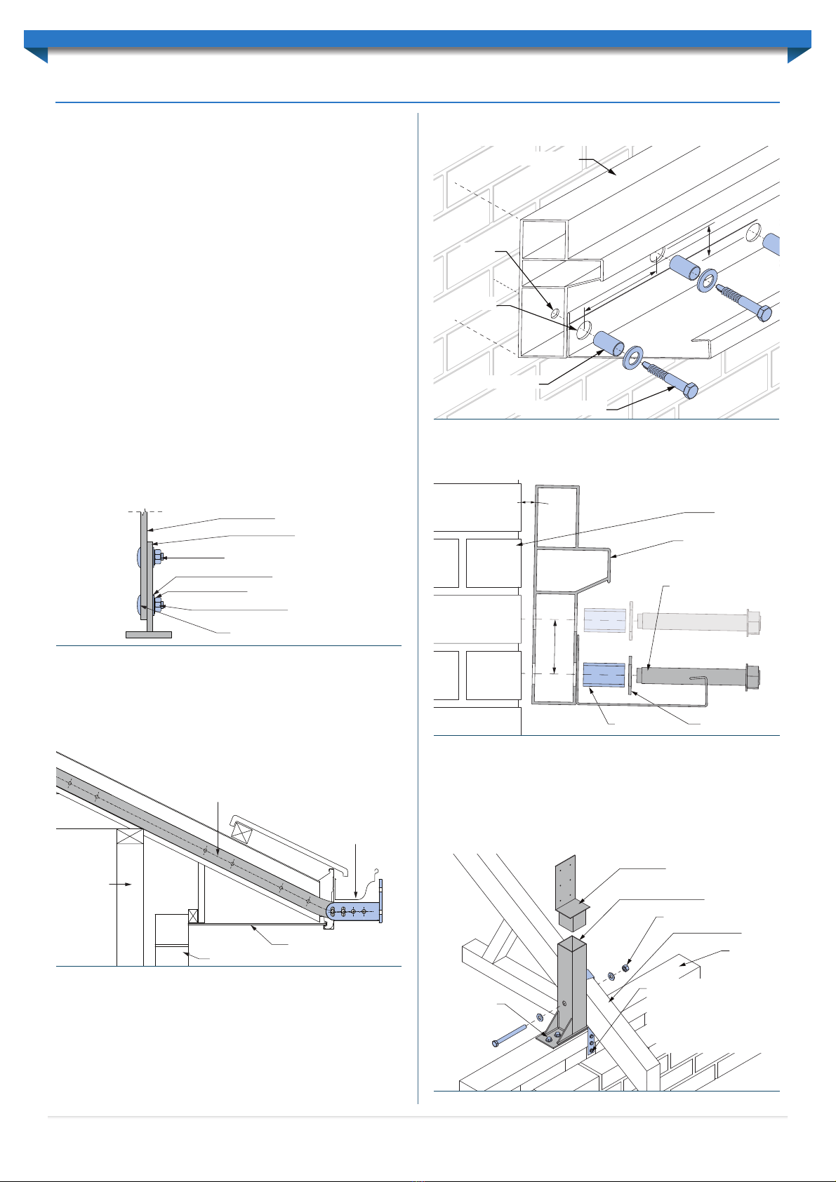
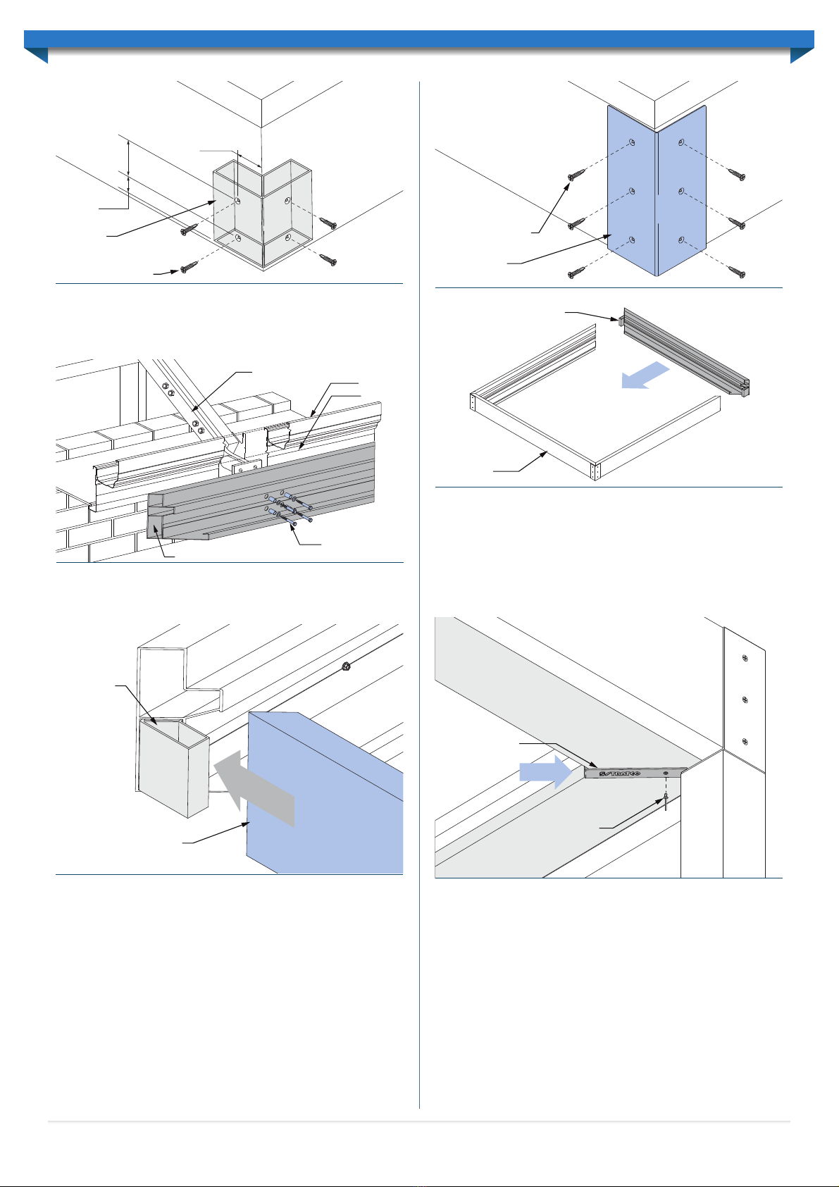
Fixing Rafter Strengthening Brackets
The adjustable rafter strengthening bracket allows for an adjustment of pitch in the
range of 15 to 30 degrees. The distance the bracket extends past the fascia is also
adjustable to allow for standard gutters with a width of up to 200mm.
Initially the bracket T piece should be fixed to the bracket arm with two M12 cup head
bolts (hand tighten only). A spring washer is to be located between the standard M12
washer and nut (Figure 1.0). Mark the position of the bracket on the fascia and notch
a rectangular hole in the fascia allowing the bracket to be fed through the front of the
fascia. The hole may need to be enlarged slightly if the M12 cup head bolts interfere
with the fascia.
Insert the bracket through the fascia and fix to the house rafter using M12 hex head
bolts through the existing holes in the bracket.Adjust the T piece so it is horizontal and
has the appropriate extension past the fascia to allow for fixing of the attachment beam.
Tighten the T piece connection bolts to a minimum of 35Nm torque.
Fix the bracket as close to the base of the gutter as possible.The recommended distance
is 10mm from the lowest end of the gutter (Figure 1.1).
Fasten the Allure attachment beam to the rafter strengthening brackets through each
hole in the attachment plate. Fix using M12 bolts, washers, & spacers as per ‘Fascia Beam
Attachment’ details on page 5.
Wall Attachment
When a unit is attached directly to a wall the attachment beam must be fixed to the
wall using M10 Masonry anchors. Fasteners should be spaced at a maximum of 500mm
centres along the beam with a ø16mm pilot hole created though the internal face of the
beam, and a ø12mm pilot hole through the external face (Figure 1.2).
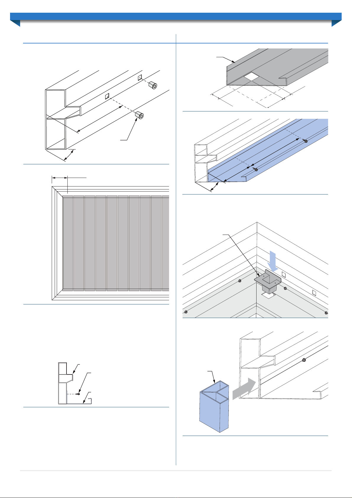
Note: The attachment beam gutter must be fixed prior to erecting the attachment
beam. See ‘Beam Preparation’ for instructions.
Every second fastener must be staggered at a vertical difference of approximately 85mm,
ensuring that each fastener is located centrally within runs of bricks (Figure 1.3).
Spacers must also be used with each masonry anchor (Figure 1.3).
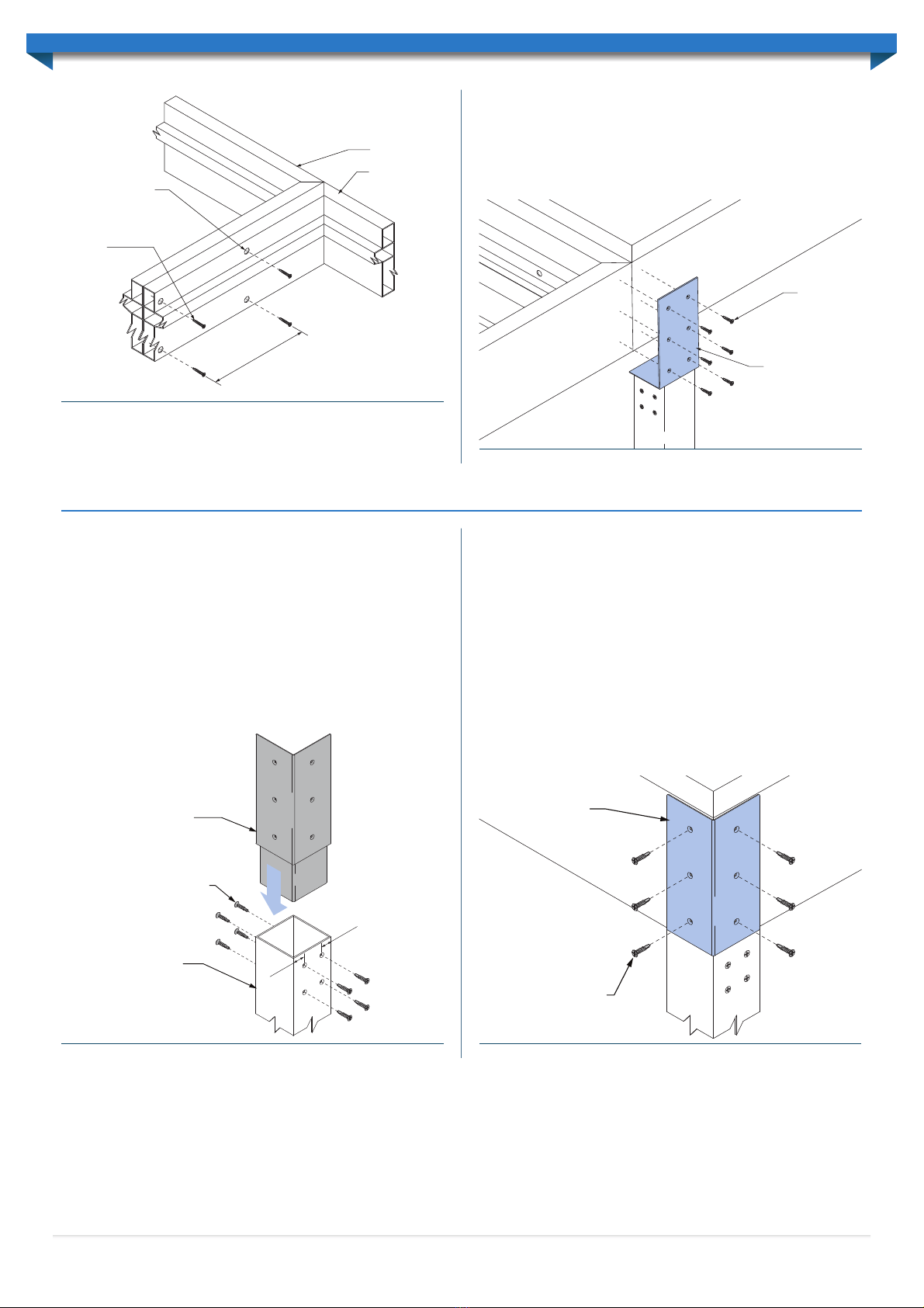
Flyover Attachment
The supplied Flyover Brackets must be secured to the structure atop the top plate and
against the rafter. Fix the Flyover Bracket to the top plate using two (2) M10 coach
screws a minimum 38mm into the top plate (Figure 1.4).The Flyover Bracket can then be
secured to the rafter using a single M12 bolt & lock nut though the centre of the rafter
(Figure 1.4). ø14mm pilot holes will need to be created through the Flyover Bracket and
rafter to accommodate the bolt.
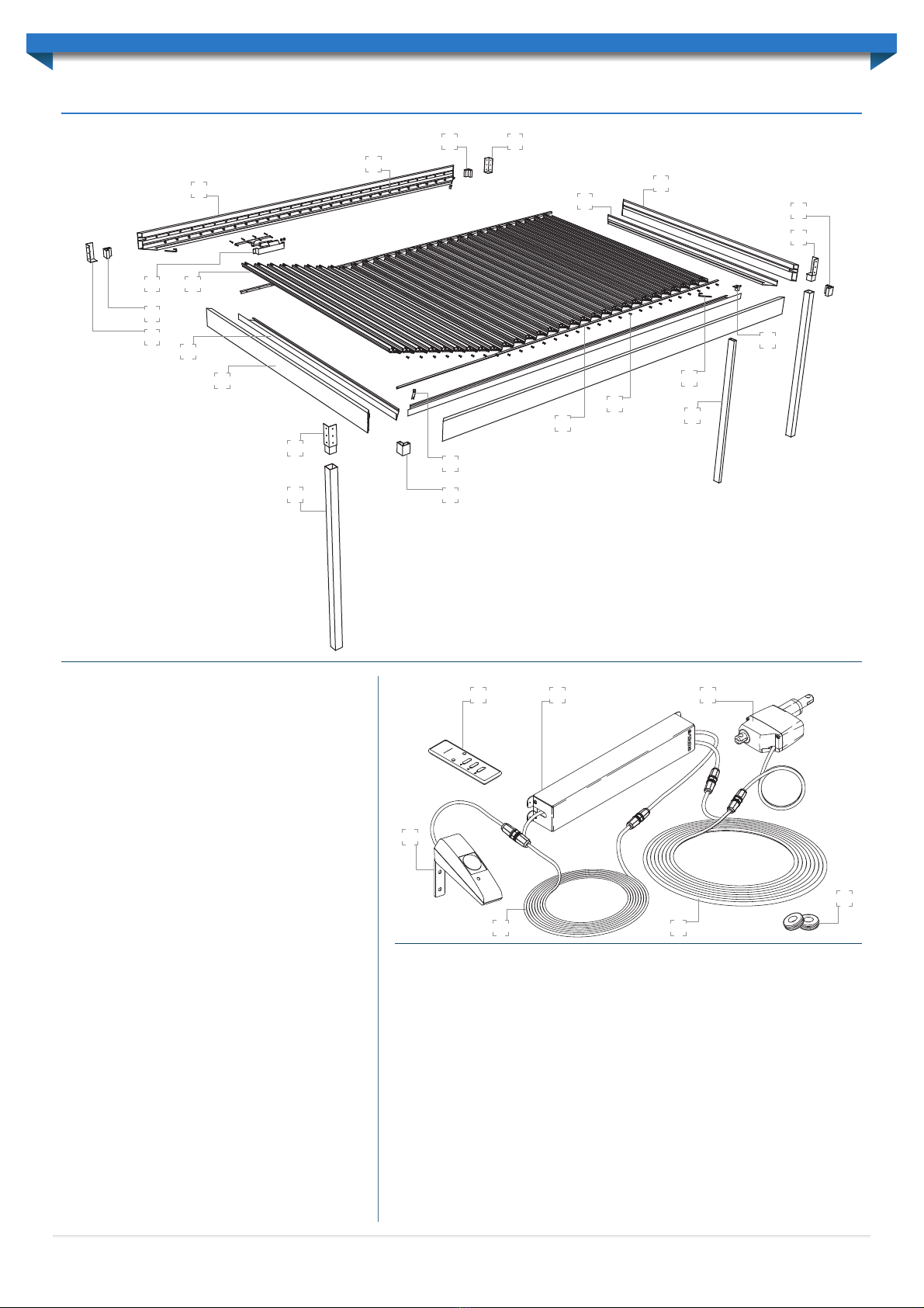
Attachment Beam
M10 Masonry anchors
500mm
8
5mm
Beam Spacer
ø16mm
ø12mm
Figure 1.2
M10 Masonry Anchor
M10 WasherBeam Spacer
Attachment Beam
Brickwork
Approx.
85mm
1°
Figure 1.3
Top Plate
M10 x 38
Coach Screws
Rafter
M12 Bolt / Washers / Nut
Flyover Bracket
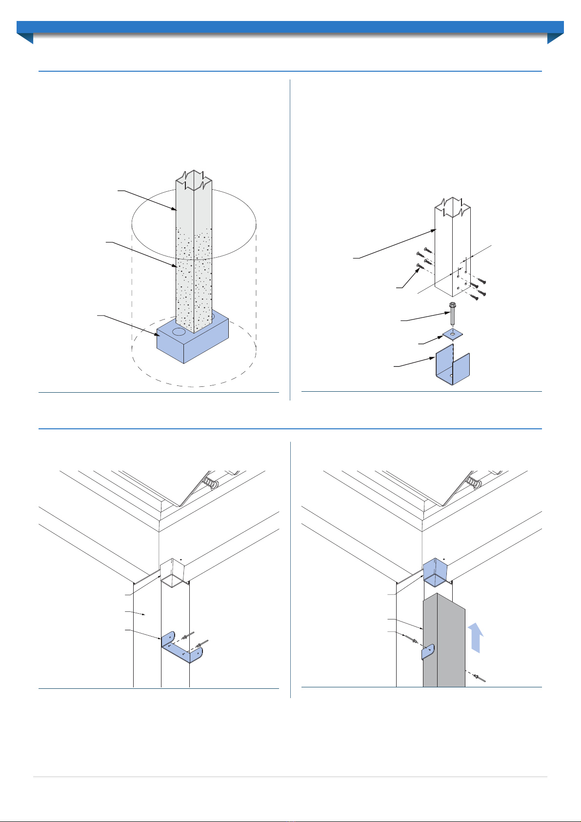
Post-Beam Inline Bracket
(refer Post Installation
32 x 1.2mm Galv metal strap
looped over truss and fixed
to stud wall with 3 M6 coach
screws each end into wallstud
and truss top chord/rafter.
(50mm min. embedment)
Figure 1.4
4
Bracket arm
M12x40 Cup head bolt
T-piece
Tighten to 35Nm torque
M12 Spring washer
M12 Nut
M12 Washer
Figure 1.0
Stud wall
Gutter
Eaves overhang
Brick work
Rafter strengthening bracket attached
to rafter with six M12 hex head bolts
Figure 1.1
ATTACHING TO AN EXISTING STRUCTURE

Note: Please ensure to follow the site plans supplied to ensure the mounting beams
are installed in the correct orientation. The Datum end of beams will be identifiable by
measuring the first mounting hole centre 270mm in from the end of the beam (Figure
2.0 & Figure 2.1).
Beam Preparation
The framework must be assembled out from the fascia beam already fixed to the
structure. If the unit is Freestanding the beams must be propped with two posts secured
as per the section ‘Post Installation’.
Internal box gutters will sit inside the assembled framework with the bottom face of the
gutters flush with the bottom face of the beams (Figure 2.2). Gutters will be supplied
already mitred to suit the frame size. Gutters must be fixed to each beam before the
framework can be erected.
Before installing the gutters the downpipe outlet location(s) must be determined. A
rectangular 45x45mm cut-out must be created on the header-beam gutter (Figure 2.3).
Make sure the cut-out is aligned with the rear internal face of the gutter.
Begin gutter installation by placing & clamping a length of the pre-mitred gutter against
the corresponding beam. Secure the gutter to the framework using 12x20 Self-Drilling
screws with Neoprene washers at 500mm centres (Figure 2.4).The end fixings must be at
least 100mm in from each end. All gutter end mitres should be flush with the beam mitres.
Continue installing the remaining gutters using the same method. Insert the Downpipe
Outlet(s) within the pre-cut holes and secure using two 3.2mm rivets (Figure 2.5). Seal
around the outlet with silicone as required.
At each Beam-to-Beam join a Corner Knuckle must be internally fitted (Figure 2.6).
Create ø3.2mm pilot holes with countersinks and fix the Corner Knuckle through
the external face of the Fascia beam using two 10gx30mm stainless steel countersunk
self-tapping screws (Figure 2.7). Countersinks should have an outside diameter of
approximately 8mm to allow the screw head to sit flush.
12x20 self-drilling screws
with neoprene washers at
500mm centres
Gutter
Beam
Figure 2.2
5
0m
m
4
5m
m
4
5m
m
Gutter
Figure 2.3
Figure 2.4
45°
50
0m
mc
e
n
t
r
e
s
10
0m
m m
i
n.
Downpipe Outlet
(rivet from
underside of gutter)
Figure 2.5
Corner
Knuckle
Figure 2.6
270mm @
Datum
45°
Mounting
Bushes
Figure 2.0
Figure 2.1
270mm
DATUM
5
FRAMEWORK ASSEMBLY

Fascia Beam Attachment
For units attached at the eaves, the Fascia beam is secured to the structure using Eaves
Fixing Brackets.Fix through the Eaves Fixing Brackets to the fascia beam using four M12
bolts with spacers and washers (Figure 2.8).
Side Beam Installation
The Side Beams must be propped in position at the required fall of 1° and over the pre-
installed Fascia Beam Corner Knuckle (Figure 2.9).
With the corner mitres aligned, ø3.2mm pilot holes must be drilled through the Side
Beams and the Corner Knuckles as per ‘Beam Preparation’.The pilot holes must also
be countersunk. Fasten the Side Beam to the Corner Knuckle using the 10gx30mm
stainless steel countersunk self-tapping screws provided (Figure 2.7).
Note: All screws within the unit must be fastened by hand using a screw-driver, or a
low-torque, low-speed drill.
Fascia Beam to Side Beam connections also require additional fastening using external
Corner Joiners. Corner Joiners must be fixed to the Fascia and Side Beams using
10gx30mm stainless steel countersunk self-tapping screws (Figure 2.10).
Once Side beams are attached the remaining Header Beam must be fixed using Corner
Knuckles as described in the previous paragraphs (Figure 2.11).
Gutter Straps
When the entire framework is erected each gutter mitre at corners can be concealed
using the Gutter Straps provided. Gutter Strap variations will be provided for corners
with posts (notched straps) and corners without (full-length straps). Slide the Gutter
Straps over the Mitres and drill a ø3.2mm pilot hole through the gutter. Fix the Gutter
strap to the Gutters using a 3.2mm rivet (Figure 2.12). If the rivet does not grip to
the gutters, a ø3mm washer may be required to sit inside the gutters to assist in fixing.
Internally seal each gutter mitre with silicone as required.
In the downpipe corner Gutter Straps will interfere with the downpipe.The interfering
gutter strap will need to be notched on-site to allow clearances.An angle grinder can be
used to trim the Gutter Strap to suit.
Multiple-Bank Frame Installation
In some instances a unit will feature multiple louvre banks.When this occurs separate
back-to-back banks are used with the banks fastened to one another. Louvres may run
parallel or perpendicular to the back-to-back beams.
When multiple banks are required all beams will be pre-mitred to facilitate installation
before going to site.
Where banks are adjacent to one another the back-to-Back beams are fixed together
using 10g x 30mm stainless steel countersunk self-tapping screws at a maximum spacing
of 600mm centres (Figure 2.13).
Gutter Strap
Rivet to gutter
Figure 2.12
Header Beam assembly
Fascia /
Attachment
Beam
Figure 2.11
Figure 2.9
Corner
Knuckle
Side Beam
10gx30 stainless steel
countersunk screws
Corner Joiner
Figure 2.10
Attachment Beam
Fascia
Gutter
Adjustable Rafter Strengthening Bracket
Four M12 Bolts with
spacers & washers
Figure 2.8
Corner
Knuckle
10g x 30mm stainless steel
countersunk screws
Fascia beam Side beam
60mm
30mm
50mm
Figure 2.7
6

A ø10mm pilot hole must be made to allow fastening through the back-to-back
wall sections. These pilot holes are sealed with a cover flashing (see ‘Installing Cover
Flashings’).
10g x 30mm stainless
steel countersunk
screws
10mmø pilot hole
Bank 1
Bank 2
M
A
X. 600mm
C
ENT
R
ES
Note: Gutters omitted for clarity
Figure 2.13
Figure 2.14
10g x 30mm
stainless steel
countersunk
screws
Inline Post-to-Beam
Bracket
Bank 2
Bank 1
Note: All screws within the unit must be fastened by hand using a screw-driver, or a
low-torque, low-speed drill.
A post is connected using Inline Post-to-Beam brackets along the header beam where
back-to-back banks meet (Figure 2.14).
See ‘Post Installation’ for further post fixing details.
7
Figure 3.0
Post-Beam
Corner Bracket
10gx30 stainless steel
countersunk screws
Corner Post
30
mm
30
mm
Post-Beam
Corner Bracket
10gx30 stainless steel
countersunk screws
Figure 3.1
100x100 SHS Posts are used to support the Allure framework. Once the framework is
assembled and set at the correct pitch, the post height measurements must be taken.
Posts sit beneath the beams and can either be fixed into concrete footings or onto
concrete. Refer ‘Footing Installation’ for further details regarding Post fixing (see below).
Posts must be cut to the length determined from the framework height measurements
(refer ‘Footing Installation’).
Post-to-Beam Brackets must be fitted at the top of each post. Corner and Inline Post-
to-Beam brackets are supplied as determined by the design of the unit. Sit the Post-
to-Beam Bracket within the Post and drill ø3.5mm pilot holes centralised and 25mm
& 65mm down from the top of the Post on two opposing faces (Figure 3.0). These
holes must also be countersunk. Countersinks should have an outside diameter of
approximately 8mm to allow the screw head to sit flush.
Fix the Post-to-Beam Bracket to the post using 10gx30mm stainless steel countersunk
self-tapping screws (Figure 3.0).
Note: All screws within the unit must be fastened by hand using a screw-driver, or a
low-torque, low-speed drill.
Position posts at the required location beneath beams. Before fixing the Post-to-Beam
Brackets to the Framework the Posts must be measured plumb using a spirit level.
Drill pilot holes through to the Beam as per the locations determined on the Post-to-
Beam Bracket saddle. Fix the Post-to-Beam bracket to the Beam(s) using 10gx30mm
stainless steel countersunk self-tapping screws (Figure 3.1).
Note: All screws within the unit must be fastened by hand using a screw-driver, or a
low-torque, low-speed drill.
Inline Post-Beam bracket connections are fixed using the same process.
POST INSTALLATION

8
Post
Duramax General
Purpose Epoxy or
equivalent
Brick
Figure 4.0 Figure 4.1
10gx30 stainless steel
countersunk screws
M12x120 anchor bolt
100x100 Post Shoe
50x50x6.0mm Washer Plate
Post
3
0
mm
3
0
mm
FOOTING INSTALLATION
Into Concrete Footings
If fixing the columns into the ground,dig the holes to the specified size. Place a half brick
in the bottom of the hole (Figure 4.0). Measure from the underside of the beam to the
top of the half brick and cut posts to this length at each post location.Any area of the
posts in contact with the concrete must be coated with Duramax General Purpose
Epoxy (or an equivalent).
Use construction props or bracing to hold columns in position, but do not concrete
the post-holes at this stage.
Onto Concrete Footings
Where posts are fixed onto concrete a Post Shoe will be used.
Fix the Post Shoe to concrete using one M12x120mm Anchor Bolt in conjunction with
a 50x50x6.0mm washer plate (Figure 4.1). Fasten the post to the Post Shoe with four
10gx30mm stainless steel countersunk self-tapping screws on either side (Figure 4.1).
Ensue screws are 30mm in from the Post edges. Countersinks should have an outside
diameter of approximately 8mm to allow the screw head to sit flush.
Note: All screws within the unit must be fastened by hand using a screw-driver, or a
low-torque, low-speed drill.
Use construction props or bracing to hold columns in position, but do not bolt to the
concrete slab at this stage.
100x50mm downpipes must be installed beneath each downpipe outlet.Downpipes will
run in-line with unit posts.
Fix the downpipe strap to the post using the rivets provided (Figure 5.0).
Downpipe
Downpipe outlet
Secure downpipe
with rivets
Figure 5.1
Post
Downpipe strap
Downpipe outlet
Figure 5.0
Slide the downpipe up and around the downpipe outlet (Figure 5.1). Secure 100x50mm
downpipe to the downpipe strap using rivets.
DOWNPIPE INSTALLATION

LOUVRE INSTALLATION
Louvre Mounting Bushes must be fitted to the mounting beams prior to louvre
installation (Figure 2.0).
Determine the correct orientation for each louvre and prepare the ends accordingly.
Slide a spring bush into the end of each spring and thread over the end cap shaft.
Louvre orientation can be determined from the Allure plans provided.
At the opposite end of the louvre, slide a plastic spacer over the end cap shaft (use the
mark on the spacer to orientate it correctly) (Figure 6.0).
Please note that the actuator will always need to be located at the same end as the spacers.
Install the first louvre by lifting it up and over the beam at the spacer end. Insert the
other end (spring end) into the first hole and compress the spring completely (Figure
6.1). Lower the spacer end and slot it into the aligning hole (Figure 6.1).
ELECTRONIC CONTROL BOX
The control box must be installed in a position that is protected from direct weather
and sharp objects.The control box must not be installed within two metres of a large air-
conditioning unit or large sources of electrical noise.A suitable location may be to mount
the box against an exterior wall directly under the eaves.Alternatively, the box could be
located within the unit box gutter, alongside the actuator (see “Install Actuator Cover”).
Fix the control box through the four pilot holes on the cover box (Figure 6.2). If fixing
to an adjacent structure use fasteners suited to the material being fixed to. If fastening
within the box gutter use four 12x20 mm self-drilling screws.
A standard single mains power point is required to be located directly next to the
control box (within 1800 mm).
Lay the main cable on the ground from the control box position to the motor position
to ensure there is enough overall cable length. The kit has been supplied with a 6m
connection cable for both the actuator and rain sensor. If additional cable is required, an
extension cable can be purchased and used for up to 18m in length.
ASSEMBLE ACTUATOR COMPONENTS
Pre-assemble the actuator components at ground level. Attach the drive arm to the
actuator with an M8x10x20 shoulder bolt and secure with an M8 washer and lock-nut
(Figure 6.3). Please note that the drive arm should be orientated so the square edge
(with 90° angle) is facing the actuator.
Note: Sunroof systems will always operate with the actuator pulling the louvres open.
The location of the actuator in relation to the opening direction of the louvres will dictate
whether a Type-A orType-B actuator kit is provided.
The appropriate orientation has been determined by Stratco, based on the opening
direction of the louvres relative to the intended motor location.
Attach the adjustment bolt to the other end of the actuator with an M8x10x20 shoulder
bolt (Figure 6.3). Secure with an M8 washer and lock-nut (do not over tighten the lock
nut). Ensure the flat surface on the adjustment bolt faces up.
Thread the M16 nut on to the end of the adjustment bolt so the nut is approximately
20mm in from the end of the adjustment bolt (Figure 6.3).
Insert the adjustment bolt through the circular cut out located in the side of the
actuator cover, and secure the cover with the M16 dome nut (Figure 6.4).
Spacer
Marking on spacer
Spring bush
Spring
Figure 6.0
Beam BeamGutter Gutter
Spacer
Link Rod Link Rod
Spring with
spring bush
Endcap Endcap
Figure 6.1
Fixing Pilot Holes (4x)
Figure 6.2
Drive arm
M8 10x20 shoulder bolt
M16 adjustment bolt
Flat edge facing up
M8 washer
M8 lock-nut
Drive arm
M8 10x20 shoulder bolt
M16 adjustment bolt
Flat edge facing up
M8 washer
M8 lock-nut
TYPE-A CONFIGURATION
TYPE-B CONFIGURATION
Figure 6.3
9
SUNROOF INSTALLATION

PREPARING LINK RODS
Lay the link rods on the ground,taking care not to bend them.The short angle should be
facing upwards. Determine where the link rod needs to be cut by counting the number
of holes required for the louvres. If the louvre bank is longer than 3m (14 louvres) a
second link rod will be required to make up the extra length. Mark and cut the link rod,
allowing 50mm overhang past the final hole (Figure 6.6).
If two link rods are required,for louvre banks over 3m (14 louvres), the link rods will need
to be joined using a Link rod joiner. Make sure to join the link rods at the uncut ends. Rivet
the link rod joiner to the link rod, through the 6 pre-drilled holes on the joiner.
Lift the link rods up and rest them along the mounting extrusion. Keep the rods straight
at all times when handling.
INSTALL LINK PINS
Connect both link rods,located at each end of the louvres, by pushing a link pin through the
appropriate hole in the link rod, and into the end cap (Figure 6.7).The link pins should push in
and snap fit into place for a solid hold.Repeat this process for the remaining louvres,ensuring
all louvres are orientated correctly and each lap is the same as the previous lap. Leave four
holes without pins where the drive arm will be fitted to the link rod.
If a link pin needs to be removed once it has been installed, squeeze the pin’s legs
together with needle nose pliers and push it towards the link rod until it releases.
CONNECT DRIVE ARM TO LINK ROD
Line the drive arm up with the four remaining link rod holes. Rotate the first free
louvre so the end cap hole is also aligned. Please note that the actuator may need to be
temporarily connected to the control box to move the drive arm to a suitable position
so the holes can be aligned.
Insert a bush through the drive arm and link rod, and into the first louvre end cap.
Similarly, insert another bush into the back of the end cap and secure with an M5 6x30
shoulder bolt and M5 lock-nut (Figure 6.8).The shoulder bolt head should be recessed
into the back of the end cap so that it is not visible.The M5 lock-nut will be located on
the drive arm side.
RUN CABLE TO CONTROL BOX
Note: The control box must be unplugged from the mains power.
Run the actuator connection cable from the actuator to the control box location.The
cable must be protected from the weather and sharp objects.The cable can be installed
so that it runs through the attachment beam, passing through the end of the beam and
fascia, eaves and finally to the control box location.
The actuator and cover are now ready to be fixed to the mounting extrusion.
INSTALL ACTUATOR AND COVER
Position the cover so the top lip hangs over the top of the internal ledge of the Beam
(Figure 6.5).The lip should be located centrally between the mounting bushes.
Note: The actuator can be located anywhere along the mounting extrusion, however,
it must be at least two louvres in from the ends and three louvres either side of a join
in the link rods.
Screw the top lip of the cover to the mounting extrusion with two 12x20 Self-Drilling
screws with Neoprene washers. Screw the front face of the cover to the mounting
extrusion with four 12x20 Self-Drilling screws with Neoprene washers (Figure 6.5).
12x20 self-drilling screws
12x20
self-drilling
screws
Locate lip centrally
between end cap bushes
Figure 6.5
Link Rod Endcap
Link Pin
Figure 6.7
Circular cut-out with
the flat edge facing up
M16 nut
M16 dome nut
Actuator
cover
Thread nut
approx. 20mm
on to bolt 90°
Circular cut-out with
the flat edge facing up
M16 nut
M16 dome nutTYPE-A CONFIGURATION
TYPE-B CONFIGURATION
Actuator
cover
Thread nut
approx. 20mm
on to bolt
90°
Figure 6.4
10
50mm
Figure 6.6

Drill a hole next to the actuator cover, ensuring it is above the gutter line. Use a 20mm
drill bit with 5mm pilot hole to drill through the front face of the extrusion and beam.
A wire pull through cable may be required to pull the cable through and out the end
of the beam.
Ensure the right end of the cable is threaded through the hole so it matches the control
box.The actuator connection cable has a 2 pin female end that connects with the 2 pin
male extension leading from the control box.
Rubber grommets have been supplied to protect the cable and must be installed at this
stage. Slit half way through the grommet so that it can be threaded over the cable and
into the hole.
Plug the 2 pin cable end into the control box and turn the power on.
USING THE REMOTE CONTROL
The remote control provided is used to control all Allure banks within the unit.
In units with multiple banks the two round buttons on the remote control are used to
select the appropriate bank channel. Channel one (1) is always used to control all banks
simultaneously.All other channels can be selected to operate banks individually.
Pressing the OPEN or CLOSE button will cause the roof to start moving in the desired
direction.The roof will continue until fully open or fully closed, or until the STOP button
is pressed.The stop button will stop the roof at any point.
ADJUSTING THE CLOSED POSITION
Use the remote control to drive the louvres until they are closed by pressing the ‘close’
button and allowing the unit to fully close.
Louvres Are Not Fully Closed
If the louvres have not closed fully, the position of the actuator must be adjusted.
Loosen the M16 nut by one to two rotations, and push the adjustment bolt away from the
actuator, through the circular cut-out in the side of the actuator cover.Tighten the dome
nut and use the remote control to open and close the louvres again (Figure 6.10). Repeat
this step until the louvres are fully closed, without deflecting the link rod.
Note: The louvres are in the fully closed position when the link rod becomes stiff (but
does not deflect) at the drive arm, ensuring it does not back drive the motor when the
‘closed’ button is released. If the actuator does back drive, this may reduce the systems life.
Louvres Are Closing Too Tightly
If the louvres have over closed, the link rod can be seen to significantly deflect.
To adjust the position of the actuator, loosen the M16 dome nut by one to two rotations,
and push the adjustment bolt towards the actuator, through the circular cut-out in the
side of the cover.Tighten the M16 nut and use the remote control to open and close
the louvres again (Figure 6.11).
Repeat this step until the louvres are fully closed, ensuring the link rod does not deflect.
INSTALLING COVER FLASHINGS
Fix the cover flashing to each end of the unit to eliminate any gaps when the louvres
are closed. Both flashings are designed to lap each end. Correct alignment is critical.The
flashings are fixed through the top of the beam with 12x20 Self-Drilling screws with
Neoprene washers at 900mm centres. Refer to Figure 6.12 for flashing layouts.
Where double-beams are used a double-beam cover flashing will need to be used to
cover the pilot holes created when joining beams together (Figure 2.13). The double-
beam cover flashing is placed over the double-beams and secured using 12x20 self-
drilling screws with neo washers along the length of the flashing (Figure 6.13).
Link rod flashings are installed along link rods with rivets at 500mm centres (Figure 6.14).
Link Rod
Drive Arm
M5 Lock Nut
Drive Bush
M5x6x30 Shoulder Bolt
Figure 6.8
Select bank
(left & right)
(multiple bank units only)
Open Louvres
Stop movement
Close Louvres
Bank Selection indicator
(multiple bank units only)
Figure 6.9
Louvres are not fully closed
Loosen
M16 nut
Move through
circular cut-out
Figure 6.10
Louvres are closed tightly with Link Rod deflecting
Loosen M16
dome nut
Move through
circular cut-out
Figure 6.11
Closing-up
cover flashing
Closing-down
cover flashing
Figure 6.12
11

Rivets
(500mm centres)
Link Rod Flashing
Link Rod
Figure 6.14
Figure 6.15
Fasten through mounting
bracket to structure using
appropriate fasteners
Attachment bracket
LED sensitivity
indicator
RAIN SENSOR
Preferably select a vertical face on the unit or adjacent structure that is open to
the weather and does not interfere with the louvre rotation and fix the rain sensor
mounting bracket using two appropriate fasteners with Neoprene washers.
Run the rain sensor cable back to the control box (an extension cord is provided
if needed). The rain sensor cable will be identified by the use of three pins in the
connectors. Use rubber cable grommets within holes in the framework as required.
Simply plug the cable into the corresponding four pin connection at the end of the
control box. Finally, tighten the plastic locking nut.
Figure 6.13
Double-Beam
Cover Flashing
12x20 Self-drilling screws with
neo washers along length
Ensure any excess rain sensor cable is not rolled into a coil as this can cause false
triggers of the rain sensor.The rain sensor cable should also be kept away from all power
cables as the induced voltage can also cause false triggers of the rain sensor.
Due to the sensitive nature of the sensor, it is likely that on occasion, small creatures,
including skinks, geckos, spiders or birds will inadvertently trigger the sensor and close
the roof.This is normal, although it can be confusing on a nice sunny day when the roof
closes automatically for no apparent reason.
The sensitivity of the rain sensor can be adjusted using a magnet that is attached to the
rain sensor mounting bracket.
To adjust the sensitivity, remove the rain sensor from the attachment bracket and
hold the rain sensor LED indicator against the magnet at the base of the rain sensor
attachment for approx. 5 seconds.
The number of LED indicator flashes represents the sensitivity settings.
One flash = Low Sensitivity
Two flashes = Medium Sensitivity
Three flashes = High Sensitivity
While the rain sensor is activated, eg, during a rain event, the remote control will not
activate the roof.The roof control unit (not the remote control) will emit a sharp ‘beep’
if the rain sensor is activated and a button is pressed on the remote control.
Once the sensor has returned to normal (eg, rain has cleared) for a minimum of 30
seconds, the rain alarm is cancelled.
The roof will not open automatically.
It is recommended that after a rain event, open the roof to approximately 30° to allow
the rain water to run off the blades and to drain to the gutters.
12

PROBLEM CHECK POSSIBLE CAUSE REMEDY
The louvres will not move
when the “OPEN” or “CLOSE”
buttons on the remote control
are pressed.
The red LED light on the remote
control unit should illuminate when
any of the buttons are pressed.
Flat battery in remote control unit. Replace battery in the remote
control unit with new CR3032.
Faulty remote control unit. Replace the entire controller
assembly and remote control unit.
Switch the power off, wait a few
seconds and then switch the power
back on. The controller assembly
should emit an audible beep when
the power is turned on.
No power at 240V ac power outlet.
Check that the 240V ac power
cord to the controller assembly is
plugged in and the power outlet is
switched on.
Check fuse/circuit breaker in
switchboard.
Use another appliance to test for
power at the power outlet.
Call an electrician if power is still
not available at the power outlet.
Faulty 24V dc power supply or
controller assembly.
Replace the entire controller
assembly and remote control unit
if power is available at the power
outlet and beep is not heard.
Press the “OPEN” and then
“CLOSE” buttons on the remote
control unit. The controller
assembly should emit audible clicks
when the buttons are pressed one
after another.
Wrong bank of louvres selected on
the remote control unit (multiple
bank patios only).
Press the left or right “SELECT”
buttons until the correct channel is
illuminated.
Faulty 24V dc power supply or
controller assembly.
Replace the entire controller
assembly and remote control unit
if power is available at the power
outlet but clicking is not heard.
If the louvres are fully closed,
press the “OPEN” button on the
remote control unit. The controller
assembly should emit an audible
beep if the rain sensor has been
triggered.
Water or contaminants on the rain
sensor.
Wait until the rain stops and the
sensor dries off or if contaminated,
carefully clean the rain sensor with
a damp cloth and dry off.
Faulty rain sensor. Replace rain sensor.
Plug the actuator directly into the
controller assembly to check if the
extension cables or actuator are
faulty.
Faulty connection.
Check that the connections
between the actuator, extension
cable and controller assembly are
secure if the actuator functions
correctly when plugged directly
into the controller assembly.
Faulty or broken extension cables.
Remove and replace the extension
cable if the actuator functions
correctly when plugged directly
into the controller assembly.
Faulty actuator.
Replace the actuator, if it does
not function correctly when
plugged directly into the controller
assembly, .
Disconnect the link rod from the
louvres and check that each louvre
rotates freely.
Louvres not square to beam,
interference between components.
Square up beams or replace
components as required.
The louvres move in the wrong
direction when the “OPEN”
or “CLOSE” buttons on the
remote control are pressed.
The actuator should retract when
the “OPEN” button is pressed and
extend when the “CLOSE” button
is pressed.
Cable connector plugged in
backwards.
Check that the rib inside the
connector with pins is aligned with
the groove on the connector with
sockets.
Mechanism installed incorrectly.
Check that the mechanism is
installed as per the installation
guide.
Actuator, extension cable or
controller assembly wired
incorrectly.
Remove cover from controller,
disconnect red and black actuator
cables from terminals labelled
OPEN and CLOSE, swap them over
and reconnect them in the terminal
block.
13
TROUBLE-SHOOTING

The louvres open
automatically when the rain
sensor is triggered.
The actuator should move in the
same direction when the “CLOSE”
button is pressed and when the
rain sensor is triggered.
The controller assembly is faulty
if the actuator moves in different
directions when the “CLOSE”
button is pressed and when the
rain sensor is triggered.
Replace the entire controller
assembly and remote control unit.
If the actuator moves in same
direction when the “CLOSE”
button is pressed and when the
rain sensor is triggered.
Refer to the remedies for louvres
moving in the wrong direction
The louvres will not close
automatically when the rain
sensor is triggered.
Hold the “STOP” button down
for 10 seconds. The controller
assembly emits two beeps when
the rain sensor is manually turned
off and a long continuous beep
when the rain sensor is turned
back on.
The remote control unit has been
used to manually turn off the rain
sensor.
Hold the “STOP” button down
for 10 seconds. The controller
assembly will emit a long
continuous beep when the rain
sensor is turned back on.
Plug the rain sensor directly into
the controller assembly to check if
the extension cables or rain sensor
are faulty.
Faulty connection.
Check that the connections
between the rain sensor, extension
cable and controller assembly are
secure if the rain sensor functions
correctly when plugged directly
into the controller assembly.
Faulty or broken extension cables.
Remove and replace the extension
cable if the rain sensor functions
correctly when plugged directly
into the controller assembly.
Faulty rain sensor.
Replace the rain sensor if it does
not function correctly when
plugged directly into the controller
assembly, .
Faulty controller assembly.
Replace the entire controller
assembly and remote control
unit if another rain sensor does
not function correctly when
plugged directly into the controller
assembly, .
« Scan this QR code with your smart phone to find a Stratco near you.
QUEENSLAND • NEW SOUTH WALES • VICTORIA
AUSTRALIAN CAPITAL TERRITORY • SOUTH AUSTRALIA
WESTERN AUSTRALIA • NORTHERN TERRITORY stratco.com.au
Ph: 1300 155 155
All brands and logos/images accompanied by ® or ™ are trade marks of Stratco (Australia) Pty Limited. ® Copyright June 2019
Table of contents
Other Stratco Accessories manuals
Popular Accessories manuals by other brands

Geomagic
Geomagic Sensable Phantom Omni Device guide

Philips
Philips 872790082082900 user manual

Safeguard Supply
Safeguard Supply WDK-2500-STROBE user manual

Ahlborn
Ahlborn ALMEMO D6 operating instructions

multicomp
multicomp 310-0900 instructions

Endress+Hauser
Endress+Hauser Turbimax CUS51D operating instructions