Stratco H1 User manual

G
G
G
G
G
UU
U
U
U
II
I
DD
D
D
D
E
E
E
E
Carefully read these instructions and refer to them constantly during each stage of construction. If you do not have all
the necessary tools or information, contact Stratco for advice. Before starting, layout all components and check them
against the delivery docket. The parts description identifies each key part.
Double check all dimensions, levels and bolting locations before cutting, screwing or bolting structural members.
• Tape Measure
• Spirit Level
• String Line
• Post Hole Digger
• Gloves
• Ladder
• Tin Snips
• Power Drill
• 5/16” Hex Head Adaptor
• Rivet Gun
• Silicone Sealant
• Concrete
Handi-Heritage Shed
H1 MODEL
BEFORE YOU START
TOOLS REQUIRED

H1 HERITAGE GARDEN SHED COMPONENT LIST
NO. COMPONENT CARTNOTE DESCRIPTION CODE QTY.
1 COLUMNS HERITAGE G/SHED PURLIN 68 2350 GAL HGP0682350GA 4/2.350
2 RAFTERS HERITAGE G/SHED PURLIN 68 1230 GAL HGP0681230GA 4/1.230
3 END GIRTS HERITAGE G/SHED PURLIN 68 2260 GAL HGP0682260GA 2/2.260
4 SIDE GIRTS HERITAGE G/SHED PURLIN 68 2260 GAL HGP0683790GA 5/2.260
5 EAVES KNUCKLES HERITAGE G/SHED EAVES KNUCKLE HGEK 4
6 RIDGE KNUCKLES HERITAGE G/SHED RIDGE KNUCKLE HGRK 2
7 BEAM BRACKET HERITAGE G/SHED BEAM BRACKET 68 GALV HGBB068GA 14
8 SIDE WALL SHEETS CGI HER G/SHED .35 D/SIDE COLOUR CGIHGS35D## 5/1.950
9 GABLE END SHEETS CGI HER G/SHED .35 D/SIDE COLOUR CGIHGS35D## 2/2.495
4/2.355
COMPONENTS
1
40
12
8
7
3
13
9
34
36
33 35
38
37
29
30
27
25
26
28
31
39
15
5
2
6
4
11 14
18
17
10
19
45
46 47
48
51
52
49
50
53
15
11 12 13
271514
16 48
FLASHING PROFILES
The following Component Lists catalogue the components required to construct your Heritage Garden Shed.
Each Heritage Garden Shed will include the components listed in the COMPONENT LIST and the PA DOOR KIT
COMPONENT LIST.
The additional Component Lists note the extra specific components required in order to complete the Heritage
Garden Shed design variations.

H1 HERITAGE GARDEN SHED COMPONENT LIST
NO. COMPONENT CARTNOTE DESCRIPTION CODE QTY.
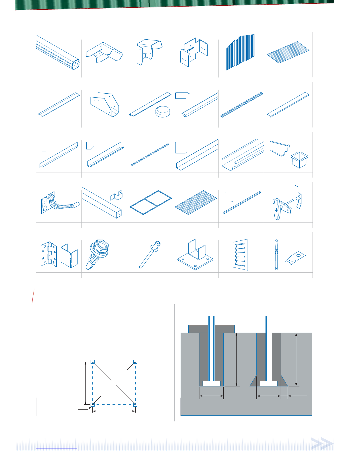
10 ROOF SHEETS CGI HER G/SHED .35 D/SIDE COLOUR CGIHGS35D## 6/1.355
11 DOOR LINTEL HER G/SHED DOOR LINTEL 1.2 GALV HDL12GA 1/0.930
12 DOOR JAMBS HER G/SHED DOOR JAMB 1.2 GALV HJA12GA 2/2.300
13 CORNER FLASHINGS HER G/SHED CORNER FLASHING COLOUR HCF## 4/2.025
14 DOOR LINTEL FLASHING HER G/SHED DOOR LINTEL FLASH COLOUR HLF## 1/0.950
15 DOOR TRIM FLASHING HER G/SHED DOOR TRIM FLASH COLOUR HTF## 2/1.890
16 SHEETING CAPPING HER G/SHED CAPPING COLOUR HSC## 2/2.500
17 BARGE ROLL BARGE ROLL 100 .55 COLOUR BRO10055## 4/1.400
18 PAINTED POST CAP PAINT POST CAP ROUND 50MM GALV FH-1032 4
19 RIDGE CAPPING ROLL TYPE RIDGE 355 .55 COLOUR RTR35555## 1/2.550
20 10X16 SELF-DRILLING SCREW TEK SCREW NO WASH 10 X 16MM TEKNNW1016 265
21 10X16 SELF-DRILLING SCREW COLOUR TEK SCREW NO NEO 10 X 16MM COLOUR TEKNNW1016## 125
22 12X35 SELF-DRILLING SCREW COLOUR TEK SCREW NEO 12 X 35MM COLOUR TEK1235## 95
23 POP RIVET RIVET 3.2X3.2 GRIP (4-2) ALUM RIV4-2 77
24 INSTRUCTIONS INSTRUCTION AND COMPONENT LIST INCLHGSH01 1
HERITAGE SHED PA DOOR KIT COMPONENT LIST
NO. COMPONENT CARTNOTE DESCRIPTION CODE QTY.
25 DOOR SHEET CGI HER G/SHED .35 D/SIDE COLOUR CGIHGS35D## 1/1.840
26 PA DOOR FRAME HERITAGE GARDEN SHED DOOR FRAME HGDF 1
27 DOOR FLASHINGS HER G/SHED DOOR FLASHING COLOUR HDF## 2/1.840
28 PA BUTT HINGE 100x75 HINGE BUTT 100X75MM F/P ZINC PLATED FH-1122 2
29 PA “T” BAR HANDLE HANDLE T SHAPE CHROME F/FIX CODE: FH-1104 1
30 PA DOOR TONGUE STRIKER TONGUE LATCH TO SUIT GARAGE HANDLE FH-1102 1
31 10x16 WAFER HEAD SCREWS WAFER HEAD TEK 10 X 16MM WTK1016 16
23 POP RIVET RIVET 3.2X3.2 GRIP (4-2) ALUM RIV4-2 8
21 10x16 SELF-DRILLING SCREW COLOUR TEK SCREW NO NEO COLOUR 10 X 16MM TEKNNW1016## 20
HERITAGE SHED GUTTER & DOWNPIPE KIT
NO. COMPONENT CARTNOTE DESCRIPTION CODE QTY.
32 DOWNPIPE STRAP D/PIPE STRAP 50X50 COLOUR DPST5050## 2
33 DOWNPIPE OUTLET D/PIPE OUTLET 50X50 COLOUR DPOL5050## 2
34 DOWNPIPE D/PIPE SQ .55 50X50 COLOUR 1800 DPSQ555050##18 2
35 GUTTER BRACKETS OG GUTTER 125 TIMBER FIX BRACKET OGG125TFX 8
36 STOP END LH OG GUTTER 125 S/END LH COLOUR OGG125STENL## 2
37 STOP END RH OG GUTTER 125 S/END RH COLOUR OGG125STENR## 2
38 GUTTER OG GUTTER 125 COLOUR OGG125## 2/2.460
LESS:
16 SHEET CAPPING HER G/SHED CAPPING COLOUR HSC## 2/2.500
OPTIONAL EXTRAS
NO. COMPONENT CARTNOTE DESCRIPTION CODE QTY.
39 LH FOOTING PLATE HERITAGE G/SHED FOOTING PLATE LH HGFPL 2
40 RH FOOTING PLATE HERITAGE G/SHED FOOTING PLATE RH HGFPR 2
41 12X20 SELF DRILLING SCREW 12-14X20 HEX TEK SCREW NO WASHER TEKNNW1220 16
42 MASONRY ANCHORS DYNABOLT HEX 8X40MM HW-4781 14
43 BOLT/NUT HEX HEAD BOLT & NUT ZP M10X20 4.6N/S HBM1020ZP 2
44 ANGLE BRACKETS 2 HOLE BENT BRACKET HW-5797 2
45 GABLE SPIRE H/SHED SPIRE 700 COLOUR HGSP700## 2

GABLE END WINDOW KIT
NO. COMPONENT CARTNOTE DESCRIPTION CODE QTY.
46 WINDOW LOUVRE WINDOW HER G/SHED COLOUR LWINHGS## 1
3 END GIRTS HERITAGE G/SHED PURLIN 68 2260 GAL HGP0682260GA 1/2.260
7 BEAM BRACKET HERITAGE G/SHED BEAM BRACKET 68 GALV HGBB068GA 2
20 10X16 SELF-DRILLING SCREW TEK SCREW NO WASH 10 X 16MM TEKNNW1016 8
GABLE END DOOR KIT
NO. COMPONENT CARTNOTE DESCRIPTION CODE QTY.
3 END GIRT HERITAGE G/SHED PURLIN 68 1990 GAL HGP0681990GA 1/1.990
47 GABLE DOOR BRACKET HERITAGE G/SHED GAB/DOOR BKT GALV HGGBGA 2
48 GABLE DOOR APRON FLASHING HER G/SHED GABLE DOOR APRON COLOUR HGA## 1/0.950
15 DOOR TRIM FLASHING HER G/SHED DOOR TRIM FLASH COLOUR HTF## 1/0.950
8 SIDE WALL SHEETS CGI HER G/SHED .35 D/SIDE COLOUR CGIHGS35D## 1/1.950
20 10X16 SELF-DRILLING SCREW TEK SCREW NO WASH 10 X 16MM TEKNNW1016 20
LESS:
14 DOOR LINTEL FLASHING HER G/SHED DOOR LINTEL FLASH COLOUR HLF## 1/0.950
GABLE END DOUBLE DOOR KIT
NO. COMPONENT CARTNOTE DESCRIPTION CODE QTY.
- PA DOOR KIT COMPONENTS - - 1
3 END GIRT HERITAGE G/SHED PURLIN 68 1990 GAL HGP0681990GA 1/1.990
47 GABLE DOOR BRACKET HERITAGE G/SHED GAB/DOOR BKT GALV HGGBGA 2
49 EXTENDED DOOR LINTEL HER G/SHED DOOR LINTEL 1.2 GALV HDL12GA 1/1.785
53 EXTENDED GABLE DOOR APRON
FLASHING HER G/SHED GABLE DOOR APRON COLOUR HGA## 1/1.805
15 EXTENDED DOOR TRIM FLASHING H G/SHED DOOR TRIM FLASH COLOUR HTF## 1/1.805
51 DOUBLE DOOR SPACER HERITAGE G/SHED DOUBLE DOOR SPACER HGDS 2
52 DROP-BOLT PADBOLT SINGLE EYE STD SHOOT 100MM HW-5927 1
8 SIDE WALL SHEETS CGI HER G/SHED .35 D/SIDE COLOUR CGIHGS35D## 1/1.950
20 10X16 SELF-DRILLING SCREW TEK SCREW NO WASH 10 X 16MM TEKNNW1016 20
LESS:
11 DOOR LINTEL HER G/SHED DOOR LINTEL 1.2 GALV HDL12GA 1/0.930
14 DOOR LINTEL FLASHING HER G/SHED DOOR LINTEL FLASH COLOUR HLF## 1/0.950
DOUBLE DOOR KIT
NO. COMPONENT CARTNOTE DESCRIPTION CODE QTY.
- PA DOOR KIT COMPONENTS - - 1
49 EXTENDED DOOR LINTEL HER G/SHED DOOR LINTEL 1.2 GALV HDL12GA 1/1.785
50 EXTENDED DOOR LINTEL FLASHING HER G/SHED DOOR LINTEL FLASH COLOUR HLF## 1/1.805
51 DOUBLE DOOR SPACER HERITAGE G/SHED DOUBLE DOOR SPACER HGDS 2
52 DROP-BOLT PADBOLT SINGLE EYE STD SHOOT 100MM HW-5927 1
LESS:
11 DOOR LINTEL HER G/SHED DOOR LINTEL 1.2 GALV HDL12GA 1/0.930
14 DOOR LINTEL FLASHING HER G/SHED DOOR LINTEL FLASH COLOUR HLF## 1/0.950
WINDOW KIT
NO. COMPONENT CARTNOTE DESCRIPTION CODE QTY.
46 WINDOW LOUVRE WINDOW HER G/SHED COLOUR LWINHGS## 1

Column Positioning
If fixing the columns into the ground, mark out the footing-
hole locations with stakes and check that the diagonal
measurements are equal (refer to Figure 1.0 & Table 1.0).
If the door positioning is known, it is best to dig the holes
for the door jambs at this point, as it can be difficult to
dig around the structure later in the process.
POSITIONING & PREPARATION
With ground slab
300(w) x 300(l)mm Without ground slab
300(w) x 300(l)mm
400mm
400mm
300mm 300mm 100mm
Figure 1.1Figure 1.0
Hole
positions
Check diagonals
Side
Gable end
68 Outback Beam Ridge Knuckle Gable Wall SheetsBeam BracketEaves Knuckle
Door Jamb Door Lintel
Door Trim
Flashing
Gable Door
Apron Flashing
Door Lintel
Flashing Corner Flashing Gutter
Downpipe
(& Downpipe Straps)
Gutter Stop-End
& Outlet
Gutter Bracket
Wall & Roof Sheets
Ridge Capping Sheet CappingBarge Roll &
Barge Cap
Gable Door
Header Bracket
Hex Head
Self-Drilling Screws Pop Rivet Spire & Spire
Bracket
Louvre WindowFooting Bracket
M10x16
M12x20
M12x35
Door Frame Door Sheet
Hinge &
Double-door bracket
Door Handle/LockDoor Flashing

Ensure that the flat side of the columns and rafters are
always facing out. Each beam has a flat edge with a
double wall thickness which should always face outwards,
as this provides a thicker wall section when fixing the
wall sheets to the frame.
Fix the column and rafter ends to the knuckles with two
10x16 self-drilling screws, locating them approximately
25-30mm from the knuckle as illustrated in Figure 2.3.
This will allow enough room (approx. 75mm) for fixing
the side girts.
To fix the end girt, secure a beam bracket 600mm in from
the bottom of each column, as illustrated in Figure 2.4,
using two 10x16 self-drilling screws. Be sure to position
the brackets in the correct orientation. Slide the end girt
into the beam bracket and fasten with one 10x16 self-
drilling screw on each side of the bracket.
For Model 3, fasten the additional end girt between the
eaves connections as described over.
Figure 2.3
75mm
(min.)
30
25
25
75
mm
(min.)
25
10x16 Hex head
self-drilling screws
Ridge knuckle
Rafters
Figure 2.2
Model Components
Frame Assembly
Insert the eaves knuckles into the column and rafter
ends (Figure 2.1), and the ridge knuckle into the two
remaining rafter ends (Figure 2.2). A gentle hammering
on the sides of the knuckles can assist in insertion.
GABLE END ASSEMBLY
10x16 Hex head
self-drilling screws
Eaves knuckle
Rafters
Figure 2.1
600mm
Check diagonals
135°
Figure 2.0
Digging Post-Holes
Dig post holes as illustrated in Figure 1.1.
Place a half brick in the bottom of the hole to ease settlement.
Alternatively, a bolted footing bracket is available if fixing
to an existing concrete slab. (Refer to section ‘Securing
Columns’)
ALWAYS FASTEN FOOTING BRACKETS TO THE CONCRETE SLAB, OR CEMENT COLUMNS IN
PLACE, AS THE LAST STEP IN THE CONSTRUCTION PROCESS.
Model Gable End Side Diagonal
H1 2400mm 2400mm 3394
H2 2400mm 3100mm 3920
H3 3100mm 3100mm 4384
H4 2400mm 3900mm 4579
Table 1.0
Component H1, 2, & 4
H3 / H3
Gable Door
or Gable
Window
H1,2, & 4
Gable Door
or Gable
Window
Column 222
Rafter 222
Gable End Girt 122
Eaves Knuckle 222
Ridge Knuckle 111
Beam Bracket 799
Table 2.0

Installing an Upper Girt
A top girt is to be integrated into a gable end within
H3 model units. The beam brackets for the girt are
positioned at the top of the gable columns and installed
as per the lower girt (Figure 2.4).
Door Jamb Installation (Gable-End Doors Only)
When doors are positioned at the gable end of a Heritage
shed a shorter end girt will be provided along with two
gable door header brackets.
The header brackets must be fastened to the gable rafters
on both sides of the gable frame with the top edge in line
with the flat plane of the rafter (Figure 2.5).
Secure the header bracket to the rafter using three 10x16
self-drilling screws on each side (Figure 2.6).
When both gable door header brackets are fastened to
the rafters, the header girt can be inserted in to each
bracket and secured with two 10x16 self-drilling screws
on each side (Figure 2.7 & 2.8).
If a door is to be installed at the gable-end, the end girt
supplied must be cut into two lengths. These lengths will
dictate the door positioning.
From one side of the gable frame, determine how far in
the door is to be positioned. Use this measurement to cut
a length of girt to size (Figure 2.9). To create the second
door girt, 880mm is to be removed from the remaining
length (Figure 2.9).
As with standard gable frames, fasten two beam brackets
to the insides of the columns as illustrated in Figure
2.4. Position and fasten a door girt to each of the beam
brackets using 10x16 self-drilling screws, making sure
the flat side with the double thickness is facing outwards.
Position the door jambs against the inside end of the
door girts, then also position the door lintel against
the bottom face of the top girt. Ensure that the lintel
is located so the front lip protrudes by approximately
20mm (Figure 2.10).
Figure 2.4
10x16 Hex
head
self-drilling
screws
Column
End Girt
Girt Bracket
Figure 2.9
880mmDoor girt 1 Door girt 2
Gable door
header girt
Figure 2.7
Figure 2.8
Gable
door
header
bracket
Figure 2.6
In line
Figure 2.5

Adjust the other jamb to suit the width of the door and
fasten as previously instructed.
Window Support Installation
(Gable-End Windows Only)
If including a window at the gable end of an H1, H2, or H4
Heritage Shed an extra girt is required for strengthening.
The existing top girt will provide sufficient strength in an
H3 model.
When constructing the frame of an H1, H2, or H4 model
an extra gable end girt is required. Position the extra
girt approximately 785mm up from the top of the lower
girt (Figure 2.14). This girt is to be fastened as with the
existing end girt.
Note: The distance of the extra girt from the lower girt
is determined by the customer’s desired window height.
Windows are to be installed after walling sheets.
Squaring the Frame
Ensure the end frame is square by checking the diagonal
measurements (Figure 2.0).
Attaching Wall Sheets
Fix the pre-cut angled wall sheets to the end frame with
10x16 self-drilling screws. Use 5 screws per sheet, per
girt and rafter, fixing through the “pan” of the profile
(Figure 2.15).
When the lintel is positioned, secure through the bottom
of the top girt using three 10x16 self-drilling screws.
Determine which side the door will open and fix the
jamb to the lintel on the side in which the door is to be
hung. Use two 10x16 self-drilling screws on each side as
illustrated in Figure 2.11. Also secure the jambs to the
door girts (Figure 2.12). Do this for both jambs, all the
while maintaining a square door frame.
Keep the jambs square by measuring the distance
between the top of the jamb and the column and
maintaining this distance between the jamb and the
column along the length of the jamb (Figure 2.13).
785mm (approx.)
Figure 2.14
Ymm
Ymm
Xmm
Xmm
Figure 2.13
10x16 Hex head
self-drilling screws
Door
jamb
Side girt (bottom)
Figure 2.12
Inside
Lintel
20mm
Top side
of girt
10x16 Hex head
self-drilling screw
Figure 2.10
Door jamb
Side girt (top)
10x16 Hex head
self-drilling screws
Door Lintel
Figure 2.11

Be sure to align the top of the sheets (angled cut end) with
the top groove of the rafter (Figure 2.16), and the outside
edges of the sheets with the outer groove of the columns.
Use a string line or measuring tape along the outside
face of the walling to locate the lower girt and maintain
an even and horizontal placement of screws.
When including a Gable-End Door the wall sheets must be
modified to suit the door positioning. Lay the first sheet
in position and mark the door jamb and lintel positioning
on the sheet. Make sure when marking out that, when
cut, the sheet will fit within the door jamb and fit around
the lintel (Figure 2.17). A rectangular notch must also
be cut in to the sheet to fit around the door lintel, as
illustrated in Figure 2.18.
Work along the Gable-End, trimming wall sheets to fit
around the door opening as necessary. The sheet edge can
then be pressed in so it tucks behind the door jamb and
around the lintel. If a window is included in the Gable-End
Notch cut in sheet
as to fit around
lintel and jamb
Door jamb
Lintel
Figure 2.18
10x16 Hex head
self-drilling screws
Beam bracket
Rafters
Figure 2.20
10x16 Hex head
self-drilling screws
Beam bracket Rafters
Column
Eaves knuckle
Figure 2.19
10x16 Hex head
self-drilling screws
Beam bracket
Column
Lower girt
Figure 2.21
Pre-cut angled wall
sheets align with top
groove of rafters
Figure 2.16
10x16 Hex head
self-drilling screws
Pre-cut angled
walling sheets
Figure 2.15
Figure 2.17
Gable-end sheets cut
to fit door opening
the wall sheets must be similarly trimmed to accommodate
the window location (see ‘Window Installation’).
Fixing Beam Brackets
Before tilting the frames into position, locate and fix five
additional beam brackets to the end frame at the ridge
joint, eaves joints, and 600mm in from the bottom of each
column at the intersection of the lower girt and columns.
Use two 10x16 self-drilling screws per bracket as
illustrated in Figure 2.19, 2.20, & 2.21.

INSTALLING THE DOOR JAMB (FOR DOORS ON SIDE)
Determine where the door is to be positioned and fix the
door lintel to the bottom side of the top girt with three
10x16mm self-drilling screws. Ensure that the lintel
is located so the front lip protrudes by approximately
20mm (Figure 5.0).
Determine which side the door will open and fix a jamb
to the lintel with two 10x16 self-drilling screws on each
side (Figure 5.1).
The door girts should be cut to size on-site as to fit on
either side of the door between the columns and door jamb.
The lengths cut will dictate the door positioning. From one
column, determine how far in the door is to be positioned.
Use this measurement to cut a length of girt to size (Figure
5.2). To create the second door girt, 880mm is to be
removed from the remaining length (Figure 5.2).
Inside
Lintel
20mm
Top side
of girt
10x16 Hex head
self-drilling screw
Figure 5.0
FIXING SIDE FRAMEWORK
To secure the side girts and ridge, slide the girts into
the beam brackets located on the inside of the gable
end frames (Figure 4.0), and fasten with one 10x16 self-
drilling screw.
Top girt
Ridge girt
Bottom girt
600mm
Tilt end frames
into position
Figure 4.0
Check diagonals
Figure 4.1
Check the frame is square by ensuring diagonal
measurements are the same, and that the columns are
vertical (Figure 4.1).
SECURING COLUMNS
Fixing in to Ground with Concrete
If fixing the columns into the ground, carefully tilt each
side panel into position and place the columns in the holes
(Fig. 4.0). Temporarily brace in position and check the wall
height is 1950mm. If necessary adjust the depth of the
hole, or alternatively cut a small amount from the column.
Fixing on to Ground with Footing Plates
If fixing the columns with footing brackets, columns will
need to be cut to length. Slide the footing bracket into
the bottom of the column and fasten with 2 12x20 self-
drilling screws either side as illustrated in Figure 3.0.
Make sure each column is vertical, using a spirit level.
Tilt each gable end into position and temporarily brace.
Note: The columns are not to be bolted to the concrete
slab, or secured with concrete, at this Stage.
20mm
20mm
M6x40 Masonry
anchor (min.
embedment
depth 30mm)
M12x20 Hex head
Self-drilling screws
Figure 3.0

Fit one of the door girts between the door jamb and end
frame and secure with two 10x16 self-drilling screws as
shown in Figure 5.3. Keep the jambs square by measuring
the distance between the top of the jamb and the column
and maintaining this distance between the jamb and the
column along the length of the jamb.
Adjust the other jamb to suit the width of the door and
screw to the door lintel.
Fix the remaining door girt between the column and door
jamb as completed previously.
Doors can be positioned at corners, with the jamb
positioned against the column and secured to the beam
brackets affixed to the column (Figure 5.5).
Flashings (Figure 5.6 & 5.7) can then be fastened as
detailed in ‘Walling & Flashing Installation’.
10x16 Hex head
self-drilling screws
Door
jamb
Side girt (bottom)
Figure 5.3
Door jamb
Side girt (top)
10x16 Hex head
self-drilling screws
Door Lintel
Figure 5.1
Figure 5.2
880mmDoor girt 1 Door girt 2
Door lintel
Opening
Door girt
Door Jamb
Figure 5.4
Door trim
flashing
Door jamb
Corner
flashing
Figure 5.6
Corrugated
sheet
Corner
flashing
Column
Beam
bracket
10x16
Self-drilling
screws
Door
jamb
Door trim
flashing
Figure 5.7
Door jamb
Beam bracket
Column
Figure 5.5

Door Assembly
Pan fix the 1840mm long corrugated sheet to the door
frame with 10x16mm self-drilling screws. Note that the
door frame is the full width of the corrugated sheet.
Cap each side of the door with the door flashing supplied.
Fasten with four pop rivets at 550mm centres (Figure 6.0).
To fix the “T” bar handle to the door, drill an 11mm
diameter hole directly into the corrugated sheeting and
the central 25x25mm tube support of the door frame
approximately 75mm in from the edge. Fix the door
handle with two 12x45 self-drilling screws. Slide the door
tongue striker over the handle shaft and fasten (this is
sometimes best left until after the door has been hanged).
Attaching Wall Sheeting
After the door has been fixed, start the installation of
the corrugated wall sheets from one gable end and work
toward the other gable end wall, making sure the overlaps
are facing away from the main viewing angle (Figure 7.0).
Wherethedoorinterruptsthesheetingrun,startsheeting
from the door opening and work towards each end. Note
that the wall sheets will need to be notched at the lintel
(Figure 7.1). The sheet edge can then be folded back so it
tucks behind the door jamb and around the lintel.
WALLING & FLASHING INSTALLATION
Toavoidcuttingthesheets,thesheetsmayneedtobelapped
several times. The sheets should be fastened to the top and
bottom girts with 10x16 self-drilling screws (Figure 7.2).
Viewing angle
Figure 7.0
Notch cut in sheeting as to
accommodate door lintel
Figure 7.1
10x16 Hex head
self-drilling screws
Door flashing
Door sheet
Rivets
Door handle/lock
Door frame
Figure 6.0
10x16 Wafer
head screw
100x75
Butt hinge
Door
Figure 6.1
DOOR ASSEMBLY & INSTALLATION
Fix two 100x75 butt hinges to the door through the door
flashing and frame with the 10x16 wafer head screws
provided (Figure 6.1).
Hanging the Door
Fix the door hinges to the door jamb using 10x16 wafer
head screws (Figure 6.1 & 6.2).
As required, use a spirit level to adjust the columns and
door jambs to create an easy to open, yet secure, door,
whilst maintaining a square framework for the overall shed
structure.
Hin
g
e Door flashin
g
Door frame
CGI door sheet Door trimRivet
10x16 Hex head self-drilling screws
Door flashin
g
Door jamb
Figure 6.2

Corner flashing
Rafter angle cut at
end of flashing
Column
Rivet
Figure 7.3
Lintel flashing
Rivet
10x16 Hex head
self-drilling screws
Door trim
flashing
Door trim flashing
Door lintel
Figure 7.4
10x16 Hex head
self-drilling screws
CGI wall sheet
(notched to fit
lintel & jamb)
Figure 7.2
Note: When installing a double-door along a side wall in an
H1 model, the wall sheets alongside the door frame will be
created from a single sheet cut on-site. The widths of the
resultant sheets will be determined by the door girt widths.
Attaching Corner Flashing
Corner flashings are to be trimmed at one end to suit
the rafter angle at each corner. Once trimmed position
the corner flashings against the corrugated sheeting in
each corner and pop rivet the corner flashings to the wall
sheets at every 600mm (Figure 7.3).
Attaching Door Flashings
Door trim flashing is to be positioned on the outside corners
of the door jambs and pop riveted every 600mm (Figure 6.0).
The door lintel flashing is to cover the door lintel and is
secured through the front face using at least two 10x16
self-drilling screws (Figure 7.4 & 7.5).
For doors positioned at gable ends a door trim flashing
is used in conjunction with a gable door apron (Figure
7.6). The gable door apron fits beneath the gable wall
sheets and is secured to the upper horizonal girt using
10x16 self-drilling screws through the sheets and apron.
An extra piece of door trim flashing is provided to cover
the lintel. The door trim is secured through the front face
using at least two 10x16 self-drilling screws (Figure 7.6).
Side Wall
Sheets
Upper
Horizontal
Girt
Door Lintel
Standard Lintel Flashing
10x16 Hex head
self-drilling screws
Side Door Lintel Flashings
Figure 7.5
Door trim flashing
Gable Door
Apron
Gable Wall
Sheets
Upper
Horizontal
Girt
Door Lintel
10x16 Hex head
self-drilling screws
Gable Door Lintel Flashings
Figure 7.6

Two doorsmust be assembled.The first doorwill becreated
in the same manner as with single door units (see ‘Door
Assembly & Installation’). The side on which the handle is
placed will determine which side this door is positioned.
The second door is to be assembled as a mirror image of
the first door, except no handle is used. Instead, before
fastening the corrugated sheet, secure a double-door
bracket to the middle of the door frame using a 10x16 self-
drilling screw (Figure 9.3).
INSTALLING DOUBLE-DOORS
Double-doors are installed in the same manner as single
doors (see ‘Installing the Door Jamb’), but the installer
must increase the spacing between door jambs as to
accommodate for an extra door (Figure 9.0).
The spacing between jambs should be approximately
1750mm.
When cutting the door girts to size from the supplied
length, rather than removing 880mm from the remaining
length, 1750mm must be removed (Figure 9.1).
An extended door lintel must be used to span the
distance between the jambs and fastened as per single-
door installation (Figure 9.0).
An extended door lintel flashing must be fastened over
the door lintels as per single-door installation (Figure 9.2)
Extended lintel is positioned
between door jambs
1750mm (approx.)
Figure 9.0
Extended lintel
flashing
10x16
Self-drilling
screws
Figure 9.2
1750mmDoor girt 1 Door girt 2
Figure 9.1
10x16 Hex head
self-drilling screws
Figure 8.1
WINDOW INSTALLATION
Figure 8.0
When installing a louvre window the walling sheets must
betrimmed to create an opening forthe window to situate
(Figure 8.0). The louvre window is to rest upon either the
extra end girt at a gable-end (H1, H2, or H4) (See ‘Gable
End Assembly’), or nest against the top girt on any side
wall or H3 gable-end. Contact against these girts will
provide extra strength and rigidity when fastened.
See ‘Gable End Assembly’ for girt construction details.
After the window opening has been created in the
walling, the louvre window can be inserted and fastened
using 10x16mm self-drilling screws through the window
frame and the outside sheeting (Figure 8.1).

Once both doors are assembled, fasten two 100x75 butt
hinges to each frame on the appropriate sides using
10x16 wafer head screws. Hang doors as detailed in
‘Door Assembly & Installation’.
Note: Be sure the clearance between doors is not tight
and both doors can open freely when unlatched.
A drop-bolt is also required on the second door. Position
the drop-bolt on the bottom-inside corner of the second
door frame. Secure using two 10x16 wafer head screws
(Figure 9.4). When the shed is fully installed and both
Double-door
bracket fastened
to door frame
Door frame
Corrugated
sheet
10x16 Hex head
self-drilling screw
Figure 9.3
Latch
Double-door
bracket
Door 1
Door 2
Figure 9.6
Drop-bolt
10x16 wafer
head screws
Door frame
Figure 9.4
Lintel
Double-door
bracket
Pad-bolt
10x16 Hex head
self-drilling screws
Figure 9.5
doors are closed and square, mark out the drop bolt
position & create a locating hole in the ground.
A pad-bolt must also be installed at the top of the second
door. Secure the pad-bolt to the top of the door frame
of the second door using two 10x16 wafer head screws
(Figure 9.5).
A hole must be drilled through the second double-door
bracket as to fit the pad-bolt. The double-door bracket
must then be fastened within the lintel, lining the hole up
with the pad-bolt when the door is in a closed position
(Figure 9.5). Use two 10x16 self-drilling screws to secure.
GUTTER & DOWNPIPE INSTALLATION
Gutter Assembly
The gutters supplied may need to be trimmed to length.
The length of the gutter should equal the distance along
the side wall, from the outside face of each gable end.
Pop rivet a left and right-hand stop end to each length of
gutter and seal with silicone (Figure 10.0).
Cut a hole for the downpipe outlet at the end of the gutter
where the downpipe is to be positioned (Figure 10.0).
Secure the outlet into position with four rivets and seal
with silicone.
Pop rivets
Gutter
Outlet
Gutter
stop-end
Pop rivet & silicone
outet & ends.
Figure 10.0

Sheet capping
Corrugated roofing
300mm
Figure 11.2
Sheet capping
Corrugated roofing
Figure 11.1
ROOFING & CAPPING INSTALLATION
Attaching Roof Sheeting
Fix the roof sheets, starting from one end of the shed. Ensure
the first sheet is square with the frame and that the roof
sheets overhang into the gutter by approximately 50 mm.
Crest fix the sheets with 12x35mm self-drilling screws
with neoprene washers, using 5 screws per sheet, per
girt. Remember the last sheet may need a greater overlap
to ensure the roof finishes as close as possible to the end
of the shed.
If gutter has not been attached, fix the sheeting capping
to the edge of the corrugated roof sheets with pop rivets
at 300mm centres (Figure 11.1 & 11.2).
Ridge cap Barge Roll
Roof sheeting
Barge cap
12x35 Hex head
self-drilling screws
Figure 11.0
20mm
Approx. 1200mm
10x16 Hex head
self-drilling screws
Figure 10.1
Position downpipe
over outlet and
fasten with rivets
Attach gutter to
gutter bracket
Fall
Figure 10.2
Gutter Installation
Crest fix the supplied gutter brackets 20mm from the
top of the wall sheets at 1200mm centres with 10x16
self-drilling screws as illustrated in Figure 10.1.
Be sure to include a slight fall along the gutter towards
the downpipe end, as this will encourage draining.
Once the gutter brackets have been installed, roll the
gutter bead onto the gutter bracket and clip the back of
the gutter into position.
Downpipe Installation
Fit the downpipe to the pre-installed downpipe outlet
using pop rivets. Fix against the wall sheets using
downpipe straps and pop rivets (Figure 10.2).

10x16 Hex head
self-drilling screws
Gable end wall sheets
Figure 12.1
Attaching Barge Rolls & Ridge Capping
The barge roll must be fixed to the roof sheets at 600mm
centres using 12x35 self-drilling screws with neoprene
washers (Figure 11.0 & 11.3). Notch the end of the barge
if a gutter has been fixed. Cap each length of barge with
a painted post cap as shown in Figure 11.3.
Note: Do not over screw as the barge will ripple.
Fit the ridge capping flush with the end of the barge,
fastening at 600mm centres with 12x35 self-drilling
screws (Figure 11.0). The ridge capping should be at a
length approximately 100mm longer than the gutter.
Notch the barge roll
as to accommodate
for the gutter
Figure 11.3
If fixing onto a concrete slab, the footing plates must be
bolted in using three M6x40 masonry anchors, and the
door jamb using a 45mm angle bracket with an M10x20
hex head bolt and M6x40 masonry anchor.
Note: Concrete is to have a minimum strength of 20MPa.
The corner hole on each footing plate will be easily
accessed. When the unit is square and level in its finalised
position, secure all footing plates to the ground through
this hole using an M6x40 masonry anchor (Figure 12.0).
Beginning on only one side of the shed, carefully remove
the 10x16 self-drilling screws securing the wall sheeting
to the lower girt (Figure 12.1). These screws must be
kept for re-fastening the wall sheets.
SECURING SHED TO CONCRETE
M6x40 Masonry
anchor
Footing plate
Column
Girt
Figure 12.0
When the wall sheets are loose from the lower girt,
unfasten the 10x16 self-drilling screws that secure the
lower girt to the beam bracket (Figure 12.2). These
screws must be kept for re-fastening the lower girt.
Now the lower girt should be free to remove from the
unit (Figure 12.3).
This has now created enough space to secure the footing
plate with M6x40 masonry anchors through the remaining
accessible holes (Figure 12.4). When the exposed footing
plate holes have been secured, the lower girt can be re-
positioned within the beam brackets and re-secured to the
beam brackets and wall sheets.
Repeat this process around the unit as to fasten all
footing bracket holes.
Remove screws from beam
brackets connecting to girt
Figure 12.2
Remove lower girt from
gable frame
Figure 12.3
Do not remove or unfasten more
than one girt at the one time.

CONTACT
1300 165 165
MAINTENANCE
FIXING A SPIRE
Drill a 12mm diameter hole into the corrugated sheeting directly in line
with the apex of the ridge.
The hole should be approximately 192mm (for 700mm spire) from the
top of the ridge.
Fix the spire to the top of the ridge with one 12x35 self-drilling screw as
illustrated in Figure 13.0.
Remove one nut and washer
from the bolt welded at the
base of the spire.
Check the spire is vertical and
plumb with a spirit level, and
thread the bolt through the
12mm hole. Fasten with the
remaining washer and nut and
seal with silicone.
Figure 13.0
Your Stratco Handi-Garden Shed will maintain its good looks for even longer
with a simple wash and wipe down.
Cleaning should be performed as often as is required to remove any dirt,
salt and pollutants.
StratcoHandi-Sheds are produced from the highest qualitymaterials and will
provide many years of service, refer to the ‘Selection Use and Maintenance’
brochure for more information on how to get the best out of your product.
INCLHGSH01
© Copyright February 2014 12/02/14
Table of contents
Other Stratco Outdoor Furnishing manuals

Stratco
Stratco Outback Flat Attached User manual

Stratco
Stratco VERANDAH & CARPORT User manual

Stratco
Stratco Outback Gable User manual

Stratco
Stratco OUTBACK MULTISPAN GABLE User manual

Stratco
Stratco DUTCH GABLE User manual

Stratco
Stratco Outback Flat Attached User manual

Stratco
Stratco OUTBACK PERGOLA User manual

Stratco
Stratco Good Neighbour Guide
Popular Outdoor Furnishing manuals by other brands

Allen + Roth
Allen + Roth GF-12S004B-1 manual

PATIOJOY
PATIOJOY HW70946 manual

Clas Ohlson
Clas Ohlson 710.194.000 Assembly and Use

Uberhaus
Uberhaus 72255013 quick start guide

Royalcraft
Royalcraft Faro Relax 3pcs Bistro Set - Slatted Wood Grain... Assembly instructions

Forever Redwood
Forever Redwood PARQUET WOODEN BENCH Assembly instructions