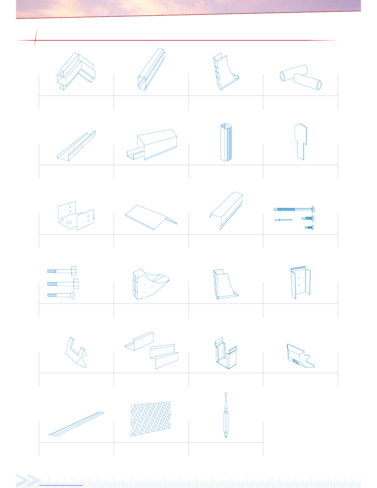
Carefully read these instructions, along with the ‘Outback Flat Attached Installation Guide’. Lay out the main
components in order of assembly on the ground and check them against the delivery note. The ‘Components’
section identies each part of your Stratco Clearspan Gable and shows the location of the components.
Mark out the overall area of your verandah, patio or carport and ensure it is free from obstructions. Beam to wall
connections can cause diculty if they coincide with door and window openings, so avoid these in your design.
Ensure there is reasonable access for materials and working space and consider the disposal of run o water.
Check the post and beam positions on the ground, roughly check they are square and mark the hole locations.
If you do not have all the necessary tools or information, contact Stratco for advice. Before starting lay out all
components and check them against the delivery docket. The parts description identies additional gable parts,
and the component layout diagram indicates their fastening position.
Outback Gable
CLEARSPAN ATTACHED
TOOLS REQUIRED
• Drill & Hex-Head Adaptor
• Rivet Gun
• Tape Measure
• Tin Snips
• Spirit Level
• Hack-Saw
• Post Hole Digger
• Silicone Gun
• Spanner or Ratchet
• Adjustable Construction Props
• Turn Up/Down Tool
• Concrete
BEFORE YOU START
BackChannel
12x20mmHex Head Self Drilling
Screwswith Domed Washers
OutbackDeck
OutbackDeck
OutbackRooflite
RoofliteInfill
FoamInsert
3mmRivets
250mm
OutbackDeck
Dipin the
profile
Nodip in
theprofile
OutbackDeck
Outback Rooflite profile
Note: each side of the profile is different, and
fits with the corresponding edge on the deck
Turndeck up
Turndeck down
Gutter EndBack Channel End
Layingdirection Prevailingwind
Bothrivets and screws
tobe located in the
panof the sheet
Back Channel FixingFixing Locations Front Fascia Beam Fixing
Back
channel
Rivetfrom
underside 12x20Hex head screws
Concreteraised
upto column
M12x75masonry
anchorsor M10x75
screwbolts
Column
Footingplate
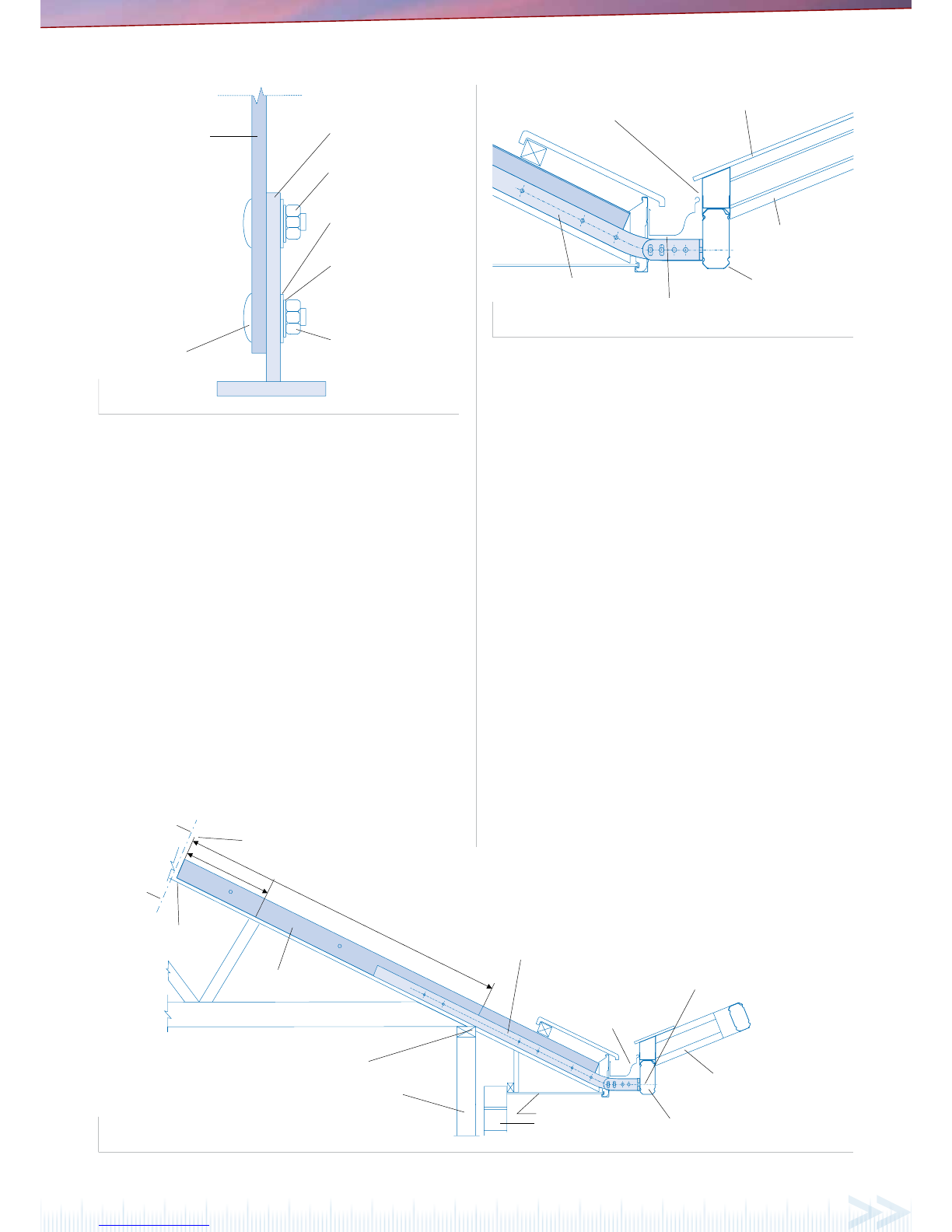
Figure 9.0 Figure 9.1
Final Fixing into the Concrete Footing
Thoroughly check the posts w ith a sp irit level. When plum b, ll the post h ole with approximately
150mm of co ncrete an d use a shove l or pole to a gitate th e concre te to remov e any air po ckets. Rep eat
this process unti l the hole is full, continually checkin g the posts as yo u go. The concrete must have
a slight slo pe that runs away from the column t o ensure any water does not pool ar ound the ba se
(Figure 9.0). Once the concrete i s set remove any temporar y bracing or props.
Final Fixing onto Existing Concrete
If the column s are to be xed to an existing concrete slab with a footing plate, each plate must be
xed to the concrete with two M12x75 masonry anchors or two M12x75 screwbolts (Figure 9.1). The
minimum distances from a n anchor hole to the concrete edg e is 75mm for M12 anchors.
Important Note
Do not allow soil to remain in permanent contact with the columns, as corrosion will result in the base
of the column. Refer to the “ Selection, Use and Maintenance o f Stratco Steel P roducts” brochur e for
complete details of the m aintenance requirement s.
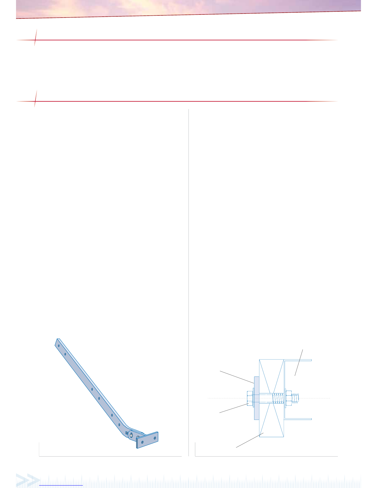
Downpipes
Before attaching the downpipe s, rivet the downpipe bracket to the column and bend the ang es along
the ‘break-line’ to ac cept the downpipe. S lide the downpipe o ver the downpipe o utlet and rivet into
position. Rivet the do wnpipe to the brackets. Weathe rproof all the fasteners w ith silicone.
Regular maintenance is essential to maintain the good looks of all Stratco steel products and to ensure
you receive the maximum life-span po ssible. Washing with cle an water must be fre quent enough to
prev ent the accumu lati on of dus t, salt s, and p ollut ants that may reduce the life of the pr oduc t. Stra tco
steel products that are regularly washed by rain require no additional maintenance. No Stratco steel
structure o r materials a re recommende d for use over, or in close proximity, to swimming pools or
spas. No material that retains water (such as dirt or paving sand) should be placed against the columns.
Care must be ta ken when determining the location of Str atco steel products so that they are not
placed in close con tact with source s of pollution or envir onmental facto rs that could a ect the life of
the steel. Refer to the ‘Sele ction, Use and Maintenance’ br ochure for more informati on.
lift the back of the gutter into the corner mitre of the side gutter. Check the roof sheets overhan g into
the gutte r by 50mm and the gu tters are squ are in relati on to the frame work. Fix th e front gutte r with
rivets at on e metre spacings t hrough the end o f the roof sheet s into the gutte r’s back lip. For uni ts
with a de ck over hang, x the gut ter to th e roof sh eets wi th two ri vets pe r pan. Ri vet and seal the f ront
gutter to the mitre and the gutter straps to the roof sheets. Lift the nal side gutter so that its front
end slides into the mitre and the stop end slides up behind the back channel. Fix the gutter in position
as previously described and waterproof with silicone. The downpipe is not attached at this stage, as
the columns are not yet xed in their vertical position.
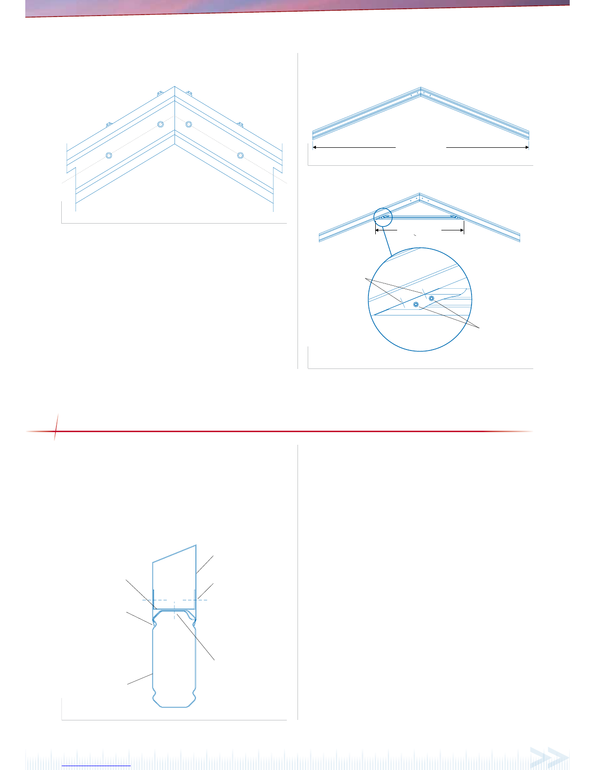
Gutter Outlet Assembly
To mark the posit ion of the outle t, place the dow npipe in line wi th the column. Ma rk and cut a hole in
the base of the gutter ne ar the back ch amfer. Inser t the downp ipe outlet from the insid e of the gutte r
and rivet in place using 3.2mm ri vets (Figure 8.1). Remove any swar f and waterproof with silic one.
Rivetpop
togutter Gutter
Gutteroutlet
(downpipepop)
Notched
beamfiller
Downpipe
A
B
120mm
120mm
Sidegutter
Frontgutter
Mitredgutter ends fit
insidethe mitre bracket
Mitrebracket
Figure 8.0 Figure 8.1 Figure 8.2
ADDITIONAL MATERIALS
TOOLS REQUIRED
• Drill & Hex/Phillips Head
Adaptors
• Rivet Gun
• Tape Measure
• Tin Snips
• Spirit Level
• Hack-Saw
It is important to check your Local Government Authority requirements before the installation of your new Stratco Outback
®Flat Verandah. It is
the builder’s responsibility to ensure any existing structure that an Outback Flat is being attached to is adequately reinforced to accommodate
the additional loads imposed by the verandah, patio or carport. Read these instructions thoroughly before starting your project and refer to
them constantly during each stage of construction. Contact Stratco for advice if you do not have the necessary tools or information.
Before starting, lay out the main components in order of assembly on the ground and check them against the delivery note. The ‘Components’
section identi es each part of your Outback Flat Verandah or Carport and shows the relative location of the components.
Mark out the overall area of your verandah, patio or carport and ensure that it is free from obstructions. Beam to wall connections can cause
di culty if they coincide with door and window openings, so avoid these in your design. Ensure there is reasonable access for materials and
working space and consider the disposal of run-o water. Check the column and beam positions on the ground; roughly check they are square
by measuring the diagonals, then mark out the column locations. If columns are to be ‘in ground’, dig the holes to Stratco speci cations.
DECKING
Turning the Decking Ends
While still at ground level, the ends of the de cking need to be turned up or
down approximately 30 de grees using a turn up/down tool to aid in weathe r
proo ng. Turn the ends of the de cking up at the ba ck channel end and down
at the gutter end (Figur e 6.0).
Laying and Installing the Decking
Decking should have a 50mm overhang into the gutter and is laid with the
overlapping r ib facing away from the pr evailing wind (Figu re 6.1). Ensure all
of the sheets have locking r ibs on the same side. Mark the back chan nel and
front fascia beam ev ery 1000mm to check the decking is l aid square.
Lift the rst sheet into pl ace and push it rmly into the BIP foam in th e
back channel to wea ther proof it. Check th e sheet is square against the back
channel an d side f ascia beam. At the back cha nnel end, rivet the decking
from und erneat h through the raised edge on the b ottom of th e back chan nel
with two 3. 2mm rivets per p an (Figure 6.2). Se al the rivets with silicone. At
each support ing beam, x the sheet with two 12x20 hex head self-drilling
screws p er pan (Figur e 6.2) (In cyc lonic cond itions use th ree 12x20 hex h ead
self-dr illing scr ews per pan o n support ing beams an d three riv ets per pan at
the back channel). Remove an y swarf.
Lay the next sheet o f decking over the previ ous sheet’s side lap (Figure 6.1).
At the back channe l end press down on the la p until the sheets clip to gether,
continue working along the length of the sheet using a timber block (to avoid
dama ging the she et) and rubb er mall et. Fi nish by slidi ng the r oof she et rmly
into the BIP foam on the back chan nel. For larger spans you may need to
temporarily suppo rt the underside of the roof sheeting w hile clipping the
laps together. Continue this p rocess until all the roof deckin g is installed.
Decking Parallel to Back Channel
If the decking r uns parallel to the back channel, slide the rst roof sheet
sideways into the BIP foam in the back cha nnel for a we ather pro of seal.
The sheeting is secured to the back channel with rivets at 200mm centres
(150mm centr es for cyclonic conditions), and it is secured to the beams
running parallel with the decking usin g hex head screws at 50 0mm centres.
The roof sheets are xed as standard to the supporti ng beams (Figure 6.2).
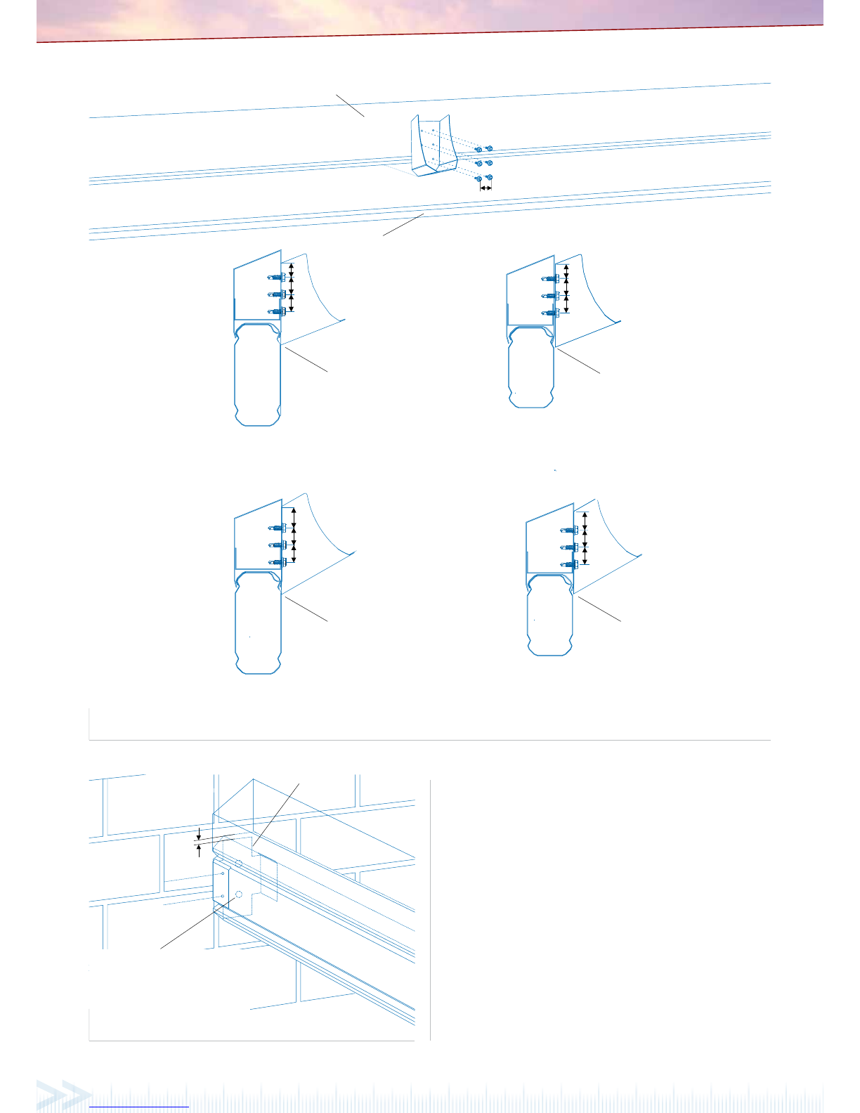
OUTBACK ROOFLITE™INSTALLATION
Roo ite is fastened using 12x20mm hex head self-drilling screws with
domed washers at maximum 2000mm cent res. Fix through the groove
located along the top of the Roo ite connectors (Figure 7.1). To nish the
exposed e nd of t he Roo ite an in ll is require d. Fasten the in ll over the
Roo ite wi th 12x20mm screws and domed w ashers on bo th sides throug h
the pre-drill ed holes. Connect t he in ll to the under side of the decking wi th
3mm rivets, seal the rivets with silicone. Finally, a foam insert is placed into
the backchannel end of the Roo ite.
An Outb ack Roo ite can b e used to add natural light. The polycarb onate
Roo ite overlaps the deck by snapping or sliding over the already installed
sheet s that hav e been sp aced 250m m apart (note the pro le of the Roo ite is
di erent on each sid e, and therefore must align w ith the correct connec tion
on the deck). Ensure the lower tab of the Roo ite touches the Outback deck
at the points shown (Figure 7.0) and all sheeting is pushed rmly into the
back channel. 9 mm holes must be pre-drilled thro ugh the Roo ite at all of
the faste ner locatio ns prior to xing to allo w for thermal exp ansion. The
Figure 7.1Figure 7.0
GUTTER ASSEMBLY
Gutter Preparation
To establish the inside gut ter length ‘A’ (Figure 8.0), measur e from the back
of the back channel to the outside of the front f ascia and subtract 5mm
for the mitre bracket. To establish the inside gutter length for units with a
deck overhang, subtract 55mm from the total ro of sheet length. To establish
inside gutter len gth ‘B’ for the front gutter, measure the le ngth of the front
fascia beam and subtr act 5mm for each mitre bracket.
Att ach th e stop ends to the si de gut ter s with four ri vet s per st op end . Remo ve
any swarf a nd waterproof w ith silicone. On t he gutter ends th at will form a
corner, cu t a 45 degree mitr e. Fit the mit re bracket s using 3mm seal ed rivets
to fasten the mitre to the gut ter then waterproof wit h silicone.
First Side Gutter Assembly
After xing a gutter mitr e bracket to th e corner of the rst side gutter, lift
the gut ter into place so the stop end slides up b ehind the back channel.
Use riv ets to fasten the gutte r’s back lip to the r oo ng a t the maximum
spacing of one metre. In stall the gut ter straps a t least ever y metre (F igure
8.2). Waterproof the rivets with silicone. Ensure th e front face of the gutter
remains vertica l and even.
Front Gutter Assembly
On the front gutter, attach a gutt er mitre to the end opposite the side gutter.
Slide the at end of the gutter strap s inside the rib of the roof sheets ever y
metre. Hang the front gutter on the gutter straps and using a rolling action,
• Post Hole Digger
• Silicone Gun
• Spanner or Ratchet
• Adjustable Construction Props
• Turn Up/Down Tool
• Concrete
• Ladder
The Outback kit does not include xings to attach the unit to an existing
structure or concrete/masonry anchors for the column installation. If
required, they must be purchased as additional items.
BEFORE YOU START
Figure 6.0 Figure 6.1 Figure 6.2
Outback
® Flat Attached
VERANDAHS | PATIOS | CARPORTS
QUEENSLAND
ORMEAU Ph: (07) 3451 4 444 1 Mavis Crt
• CRESTME AD Ph: 3451 4 411 179 Magnesium D ve
• TOOWOOMBA Ph : 4638 9 322 167 Herries S t
• VIRGINIA Ph : 3451 4411 1/2 043 Sandg ate Rd
• CABOOLTUR E P h: 5431 4 100 17C oncorde Pl
• MAROOCH YDORE Ph: 53 51 0100 14 Pike St, Ku nda Park
• GOLD COAST Ph : 3451 4411 108 Ea stlake St, C arrara
• CAPALA BA Ph: 3451 4 411 Cnr. Smith St & Redl and Bay Rd
• ARCHERFI ELD Ph: 345 1 4411 Cnr. Beaudes ert & Granar d Rd
• REDBANK PL AINS Ph: 3 451 4411 326 Kru ger Pde
NEW SOUTH WALES
HUNTINGWOOD Ph: (02) 8811 7200 15 Lib erty Rd
• CAMPBEL LTOWN Ph: 8811 7 211 22 Blaxlan d Rd
• PENRITH Ph : 8811 7211 125 Coree n Ave
• THORNTON Ph : 4922 27 77 2H artley Dv e
• ORANGE Ph: 6 362 2160 5 Colli ers Ave
AUSTRALI AN CAPITAL TERRITORY
FYSHWICK Ph: (02) 628 0 5905 25 Tenn ant St
VICTORIA
EPPING Ph: (03) 9409 9 260 17 Scanlon Dr
• DEER PARK Ph: 9 409 926 0 1027 Western H wy
• FERNTRE E GULLY Ph: 940 9 9260 881 Bu rwood Hwy
• DANDENONG Ph : 9409 92 60 14 Princes Hwy, Doveton
SOUTH AUSTRALIA
GEPPS CROSS Ph: (08) 8 349 5559 125 C avan Rd
• RICHMOND Ph : 8349 5 559 221 Marion Rd, Marleston
• ST MARYS Ph : 8349 55 59 1197S outh Rd
• LONSDALE Ph : 8349 55 59 Cnr. Dyson & O’ Sullivan Be ach Rd
• ST AGNES Ph : 8349 55 59 129 Tolley Rd
• GAWLER Ph: 85 22 1132 16 Main Nort h Rd, Willas ton
• GOOLWA Ph: 855 5 2825 29 Hutchinson St
• VICTOR HA RBOR Ph: 85 52 5164 95 Vict oria St
• MURRAY BRID GE Ph: 8531 9 191 15H indmarsh Rd
• KADINA Ph: 8 828 1555 9 Kenn ett St
• RIVERLA ND Ph: 8582 4 666 53 Zant e Rd, Berri
• PORT AUGUS TA P h: 864 2 0300 70 Victo ria Pde
• WHYALLA Ph : 8645 73 44 50 Ian St, Why alla Norrie
WESTERN AUSTRALIA
CANNING VALE Ph: (08) 9455 5111 183-189 Ba nnist er Rd
• MALAGA Ph : 9455 5111 Cnr. Mar shall Rd & Energ y St
• BALCATTA Ph : 9455 5111 140 Bal catta Rd
• MANDURA H Ph: 9455 5 111 11 Fi tzgerald R d
• BUNBURY Ph : 9791 420 0 Cnr.S trickla nd St & Zaknic P l
• BUSSELTON Ph: 9 752 3122 18 Wrigh t St
• KALGOOR LIE Ph: 9080 8080 8 Fede ral Rd
• BROOME Ph: 919 1 3800 26 Hunter St
• KUNUNURRA Ph: 9169 19 00 2C ocus Wy WA
NORTHERN TERRITORY
BERRIMAH Ph: (08) 894 4 2300 780 Stuar t Hwy
• ALICE SPRI NGS Ph: 895 0 9898 6 Ghan Rd
NEW ZEALAND
CHRISTCHURCH Ph: (03) 338 90 63 5 5 Hands Rd
• NAPIER Ph: ( 06) 843 6 159 65 Niven St, On ekawa
www.stratco.com.au
All brands and logos/images accompanied by ® or ™ are
trade marks of Stratco (Australia) Pty Limited.
BROCDAO
© Copyright October 07 7k/8/12