Strava 100.600 User manual

©Copyright 2021 Strava Solutions, LLC All rights reserved
Manufactured by:
STRAVA SOLUTIONS
2733 Kanasita Drive #125
Hixson, TN 37343 USA
STRAVA & ROLYAN
SPLINT BATH
SERVICE MANUAL
REF 100.600 Strava Standard Size
REF 100.500 Rolyan Standard Size
REF 100.600E Strava (Euro)
REF 100.500E Rolyan (Euro)
REF 100.600A Strava (Aussie)
REF 100.500A Rolyan (Aussie)
REF 100.600UK Strava (UK)
REF 100.500UK Rolyan (UK)
This manual must be given to a
qualied service technician to
perform maintenance and service
on the splint bath. Please read and
save for future reference.
PART NUMBER: 400.605 Rev 1 Strava Service Manual

©Copyright 2021 Strava Solutions, LLC All rights reserved
CONTENTS
Inspection 3
Contents of Box 3
Safety 3
Symbols 4
Technical Data 5
Material 6
Unit Instructions 7
Initial Set Up / Function Check 7
General Use 8
Storage and Handling 9
Error Messages on Control Panel 9
Glass Replacement 10
UV Ballast Replacement 11
Pump Occlusion 13
Heating Element Replacement 15
Software Upgrades 16
Replacement Parts / Service Kits 17
Warranty/Replacements 17
Service Life 17
Contact the Manufacturer 17

©Copyright 2021 Strava Solutions, LLC All rights reserved
PAGE: 3
Inspection
Safety
Contents of Box
Prior to shipment, the water baths are subjected to a thorough safety-related and functional quality
control and are carefully packed.
Check ALL parts for shipping damage. If shipping damage is noted, DO NOT USE. Contact dealer/
manufacturer for further instruction.
Products may only be returned in undamaged cardboard packaging – with foam corner inserts.
The safety section contains important information for the safe operation and use of this product. Read
this information and any other safety information included with the product before using the splint
bath.
The Electric Shock Symbol is used to indicate a hazard arising from dangerous voltage. Any
mishandling could result in severe injury or death. The Exclamation Symbol appears in Warning and
Caution statements.
1. Splint Bath – Standard REF 100.600
2. User Manual REF 100.500
3. One of the following:
Power Cord (US) REF 300.107
Power Cord (Euro) REF 300.154
Power Cord (UK) REF 300.155
Power Cord (AU) REF 300.156
(do not use a detachable mains power cord with inadequate ratings to the Strava cord)
4. 8 ft Drain Hose REF 200.101
5. Strainer REF 300.128
6. Priming Bulb REF 300.127
SPLINT BATH
SERVICE MANUAL
WARNING
To avoid electric shock, connect the instrument to properly earth-grounded, GFCI protected, 3-prong
receptacles only. Failure to observe this precaution can result in severe injury.

©Copyright 2021 Strava Solutions, LLC All rights reserved
PAGE: 4
DANGER!
CAUTION!
WARNING!
Danger indicates an imminently hazardous situation which, if not avoided, will result in death or
serious injury.
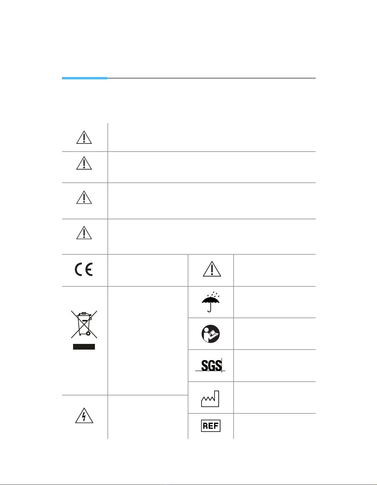
European Union CE mark.
The CE mark indicates that this
product satises the relevant
requirements of EC Directives.
Electric Shock
The Electric Shock Symbol is
used to indicate a hazard arising
from dangerous voltage. Any
mishandling could result in severe
injury or death.
Waste Electrical and Electronic
Equipment (WEEE)
This symbol on the product or on
its packaging indicates that this
product must not be disposed of
with regular waste. Instead, it is the
user’s responsibility to dispose of
waste equipment according to the
local laws. Separate collection and
recycling of the waste equipment
at the time of disposal will help
conserve natural resources and
ensure it is recycled in a manner
that protects human health and
the environment. For information
about where the user can drop o
the waste equipment for recycling,
please contact your local waste
collection authority.
Caution, consult the
instructions for use.
Keep dry
Refer to User Manual
Product Certication Mark
Year of Manufacture
Catalogue Number
Caution indicates a potentially hazardous situation which, if not avoided, may result in property
damage or minor injury or both.
Warning indicates a potentially hazardous situation which, if not avoided, could result in death or
serious injury.
- Failure to follow these instructions could result in damage to your new heating appliance and/or injury
DANGER!
CAUTION!
WARNING!
Signal words are used in this manual and apply to hazards or unsafe
practices which could result in personal injury or property damage. See the
information below for denitions of the signal words.
SYMBOLS
This symbol designates where personal injury or damage to the equipment is possible.

©Copyright 2021 Strava Solutions, LLC All rights reserved
PAGE: 5
•This water bath is not suitable for direct heating without using water.
•The water bath is only intended for the heating of thermoplastic material for medical use.
•The heating of food and drinks, as well as other pharmaceutical and medical products,
is not allowed and constitutes improper use.
•Direct application on the patient is not allowed.
TECHNICAL DATA
Technical Specifications Strava and Rolyan Splint Bath
SPLINT BATH STD UM Spec
Operating Temperature Range F 140o - 180oF
C 60o - 82oC
Temperature Variability F/C 2o
Sanitation Mode F 185o
Set Time Seconds 30 - 180
Storage (Altitude) ft 16,732 ft
Operation (Max) ft 16,732 ft
m 5100 m
m 5100 m
C 85o
Over Voltage W 11
Frequency Hz 50/60 Hz
Mains Voltage (+/- 10% of nominal voltage) V 100-120 VAC, 200-240 VAC
Power Consumption W 1100W
AC Current (Max) A <10 Amps
Water Fill Capacity Gallons 5.2 G
Litres 20 L
Water Fill Height in 5”
cm 12.5 cm
Unit Weight lbs 35 lbs
Unit Shipping Weight lbs 47 lbs
kg 15.9 kg
kg 21 kg
Unit Dims Outer (LxWxH) in 22.625”L 19.75”W 10”H
Unit Dims Inner (LxWxH) in 19”L 12”W 6”H
Unit Shipping Dims (LxWxH) in 26.5”L 23”W 16”H
cm 60cm L 52cm W 25.5cm H
cm 48cm L 30cm W 15cm H
cm 67cm L 59cm W 41cm H
Standard IEC 61010-1, -2
Environment (Altitude)
UL 61010-1, -2
CSA C22.2#61010-1, -2
CB SCHEME

©Copyright 2021 Strava Solutions, LLC All rights reserved
PAGE: 6
1 – Target temperature display
2 – Actual temperature display
3 – Temperature display mode °C/°F
4 – Time control up or down
5 – Timer START/STOP button
6 – Timer – time count down display
7 – Presets wheel
8 – Temp control up or down
9 – Menu
10– Add a new preset
11 – Power down unit
4
8
7
9
4
8
7
10
11
2
13
5
6
Top Side of UnitSide of Unit
25.5cm
(10”)
60cm
(22.625”)
52cm (19.75”)
Rear of Unit
Inner Tub
30cm x 48cm x 15cm
(12” x 19” x 6”)
(w x l x h)
Material
The outer chassis material is a thermoset composite material. The unit consists of a tempered glass lid,
drainage hose, water strainer, water pump, power supply and ultraviolet (UV) light.
Control Panel

©Copyright 2021 Strava Solutions, LLC All rights reserved
PAGE: 7
Initial Set Up/Function Check
NOTE: USE TAP WATER TO FILL UNIT. IF YOU ARE IN A HARD WATER ENVIRONMENT
WHERE DISTILLED WATER IS PREFERRED, ADD ONE CUP OF TAP WATER TO EVERY
GALLON OF DISTILLED. UNIT WILL NOT FUNCTION PROPERLY IF DISTILLED WATER IS
EXCLUSIVELY USED.
1Plug the Strava supplied power cord (do not use any other
power cord other than supplied by Strava) into the back
of the unit and a dedicated wall receptacle. (Protective
Earthing - a dedicated electrical circuit is required). Fill the
reservoir with water just above the water sensor
(approximately 2”/5cm). Flip the switch at the back of the
unit to turn the unit “on”. At initial powering up of the bath,
the start up wizard will display on the LCD screen.
•Start up wizard will prompt user to set time, day of the
week, and temperature.
•Note: Sanitation cycle defaults to “on”.
2Unit must be primed before operation. Insert the supplied
priming bulb into the priming port. Squeeze the bulb once
and hold it until the bulb is fully inflated. Release the tip of
the priming bulb from the port. You should see the water
start to bubble at the port. You will also notice a slight
change in the sound of the motor. If this doesn’t occur,
repeat up to 3 times. Once the water bubbles , the unit is
primed. This process removes any trapped air in the tubes
and allows the pump to engage.
3Continue filling the tank to desired water level or to the
bottom of the internal hinge line.
UNIT INSTRUCTIONS
WARNING: Do not start the unit if the cable or plug is damaged, or if there are
obvious, visible defects to the unit.
Priming bulb

©Copyright 2021 Strava Solutions, LLC All rights reserved
PAGE: 8
General Use:
Emptying the Water:
Cleaning the bath:
•Once the unit is filled to desired water level, the power is on, the preset is fixed, and the set
temperature has been reached, the unit is ready for the thermoplastic materials.
• Insert the splinting material into the reservoir, being careful not to splash hot water outside
the tank.
• Press start (green button with arrow on home screen). At any time during a session, the timer
can be paused and restarted from the beginning or from the time the unit was paused.
• To maintain an accurate water temperature, retain heat, and minimize evaporation, keep
lid closed.
• Use caution when retrieving the material from the bath. Apply the material to the patient as
er the splint manufacturer’s instruction.
• Maintain sufficient water level at all times. (approx 3”/7.62cm deep).
•Allow the water to cool before water evacuation. Water will not drain unless the water
temperature is below 165o F/74o C.
•Be sure that the drain hose is properly inserted at the back the unit. The water will not
drain if the hose is not connected.
•In the menu on the control panel, click on H2O Evacuation and press start.
•Once the bath is empty, proceed with tank cleaning.
•Strava recommends a minimum of a monthly water reservoir cleaning (more frequently if
conditions warrant it).
• Turn the power switch off and unplug the unit from the wall receptacle.
• Evacuate the water.
• With a soft cloth, wipe out the tub with mild dishwasher detergent. Rinse thoroughly with clean
water and wipe dry.
NOTE: SANITATION WIPES (CAVIWIPES, SANIZIDE, ETC) CAN BE USED TO WIPE OUT THE TUB. DO NOT USE
ANY BLEACH PRODUCTS, DILUTED BLEACH, HYDROGEN PERIOXIDE OR PEROXIDE-BASED AGENTS.
• Using a vinegar and water solution or a commercial descaling solution to clean mineral deposits
on and around the glass lid.
NOTE: DO NOT USE SANITATION WIPES ON THE GLASS LID OR THE CONTROL PANEL FACE PLATE.
• Strava recommends a periodic descaling of the unit to remove any potential mineral build up on
the heating element, UV system and internal water pump. Run a commercial descaling solution
through the unit as per directions on the product (i.e Mulituse CLR, Zep, Keurig descaling solution,
etc). on and around the glass lid.
• Refill with clean water as per instructions for filling the tank.
NOTE: IF DISTILLED WATER IS USED, ADD ONE CUP OF TAP TO EVERY GALLON OF DISTILLED.
NOTE: REFER TO THE USER MANUAL FOR DETAILED INSTRUCTION USING THE SPLINT BATH.
NOTE: THE WATER PUMP AND UV LIGHT ARE ALWAYS ON DURING NORMAL OPERATION OF THE UNIT.

©Copyright 2021 Strava Solutions, LLC All rights reserved
PAGE: 9
Error Messages on the Control Panel
Over temp:
If the unit exceeds 195o F (91oC) turn off main power and contact technical service at
Low water:
1. If there is water in the reservoir, make sure that the tank is NOT filled exclusively with
distilled water. The unit must have some tap water in it for the sensor to register the water
level. If there is tap water in the reservoir, turn off the main power and contact technical
service. The recommended amount of tap water is 1 cup/gallon of distilled water.
2. If there is no water in the reservoir, turn off the main power and investigate possible
causes - water evaporation or unit leakage.
•Water evaporation - always maintain adequate water volume in the tank.
• Water leakage - turn off main power and contact technical service.
UV lamp defective:
Turn main power off. Unplug cord from unit and wall. Remove rear access panel via 4 screws.
Carefully remove black rubber boot from UV housing, allowing the lamp to slide out of the
housing. Disconnect lamp from connectors on both ends. Replace bulb. Reconnect at both ends
and insert new bulb back into the housing. Attach rear access panel. Dispose of defective bulb
according to local regulation.
Temp sensor error:
Refers to the water temperature exceeding 195oF (90.5oC). If the over temp error message displays:
1. While evacuating the water, pause evacuation, wait for the water to cool, then resume
evacuation. Unplug cord from unit and wall. Contact technical service.
2. During standard operation, unplug cord from unit and wall. Contact technical service.
Storage and Handling
•Check the power cord and plug for excessive wear or fraying. Replace as needed.
Do not use a detachable mains power cord with inadequate ratings. Only replace
with a Strava power cord.
It is recommended the following guidelines are used whenever this system is being stored
or transported to another location:
Operation: 32oF – 104oF (0oC – 40oC)
Storage: 32oF – 140oF (0oC – 60oC)
2Pollution degree
Operation: Up to 80%
Storage: Up to 90%, non-condensing
Environment
(Temperature)
Environment (Humidity)

©Copyright 2021 Strava Solutions, LLC All rights reserved
PAGE: 10
Step 1: Remove old glass
•Open and retract the glass lid to approximately the half-way point.
Figure 1
NOTE: ON ALL PROCEEDING STEPS, ASSISTANCE WITH A SECOND PAIR OF
HANDS IS REQUIRED
•With a 3mm allen wrench (used for outside glass) and 7 mm nut
driver (for the inside of glass), remove the two acorn nuts and
hardware screws from both of the back hinges (4 total). Figure 2
•Place the old glass to the side. Figure 3
Step 2: Installing the new glass
NOTE: ON ALL PROCEEDING STEPS, ASSISTANCE WITH A SECOND PAIR OF
HANDS IS REQUIRED
•Align and hold the new glass holes with the hinge holes with person 1.
Figure 4
•With the second set of hands, install the male sex bolt with nylon
washer inserting from the outside of the glass into the outermost hole
of hinge. Figure 5
•Install the nylon washer on the inside of the glass onto the sex bolt,
followed by the acorn nut. Figure 6
•Repeat on the opposite hinge with the other set of hardware. Figure 7
•With one hand holding the sex bolt and one hand holding the acorn
nut, hand tighten until it stops.
•Fold glass at midpoint making an A frame and ensuring that the glass
edge is on track. Figure 8
•Complete the hardware install by installing the remaining two sex bolt
assemblies into the hinges, securing all 4 sets with a hand tight.
Figure 9
•Fold glass down.
•Facing the front of the unit, use both hands on the back of the glass
pane and pull the glass towards you for proper alignment. Figure 10
•With the handle side on track, carefully fold glass up to the midpoint
of the bath. Proper alignment here is critical.
•While holding the 7 mm nut driver on the back side of the acorn nut,
and the 3mm allen wrench on the sex bolt, tighten the sex bolt
clockwise. Figure 11
•Tighten the two outermost holes first on left and right. Then, before
securing the remaining two, fold glass down to ensure proper shutting
of lid. If adjustment is needed, loosen bolts and re-align.
•Repeat tightening procedure on the innermost bolts.
Figure 1
Figure 4
Figure 6
Figure 8
Figure 10
Figure 2
Figure 5
Figure 7
Figure 3
Figure 9
Figure 11
Glass Replacement:
If the unit suffers broken glass anywhere on the lid, the entire glass lid needs to
be replaced.
A glass lid assembly is needed to perform this operation.
Glass Lid Assembly Kit: REF 200.303
Kit consists of 2x glass panes with center hinges, handle and 4x male sex bolts,
8x nylon washers and 4x acorn nuts, 3mm allen wrench, and 7mm nut driver.

©Copyright 2021 Strava Solutions, LLC All rights reserved
PAGE: 11
UV Ballast Replacement:
If the UV bulb has been replaced and the UV system is still not working, the
next step is to replace the UV ballast.
A UV Ballast Assembly Kit is needed to perform this operation.
UV Ballast Assembly Kit: REF 200.301
Kit consists of UV ballast, bulb harness and two wire ties.
Step 1: Dismantle the splint bath
•Unplug splint bath from wall
•Find a soft surface to put splint bath on
•Tape glass lid closed
•Turn splint pan upside down and gently lay unit on its face, ensuring
that glass lid stay intact. Figure 12
•Use a 3/32” allen head or #2 Phillips screwdriver, remove all (13)
screws from black base pan and place to the side. Figure 13
•Once base pan is removed, use a 3/32” allen wrench to remove the
two screws off of the back panel. Figure 14
•Remove the two screws from the scissor draw with a 3/32” allen
wrench. Figure 15
•Lift the scissor drawer out of chassis, providing access to the
internal control panel. Figure 16
Step 2: Remove the old UV ballast
•Pull out the existing UV bulb from the UV housing and unplug it from
the harness. Set aside. Harness will hang freely. Figure 17 & 18
•Remove the two wire ties at the front and back of the UV housing.
•Feed the UV harness back through back panel. Figure 19
•Loosen the bottom ballast screw with a #1 Phillips screwdriver with
two turns ONLY. Completely remove the top ballast screw to release
the ballast. Figure 20 & 21
•Rest ballast on top of the control panel.
•Follow the wire harness from the ballast to the bottom of the control
panel. Cut the wire tie there, freeing the ballast harness.
•Trace the ballast wire harness to the #3 terminal (from top) on the
PCB control board. Figure 22
•Firmly grasp all wires on #3 terminal with fingers and pull straight out.
•Ballast assembly is now free from the unit (ballast + harness.)
Figure 23
Figure 12
Figure 18
Figure 14
Figure 20
Figure 16
Figure 22
Figure 13
Figure 19
Figure 15
Figure 21
Figure 17
Figure 23

©Copyright 2021 Strava Solutions, LLC All rights reserved
PAGE: 12
UV Ballast Replacement cont. :
Step 3: Install the new UV ballast
•Remove new ballast assembly from box.
•Feed the wire harness through the back panel.
•Line up the black harness to the top of the control panel and wire
tie in same two locations as removal. Cut off excess.
Figure 24
•Feed the connecting end under the solenoid and firmly plug into
terminal #3.
•Use the bottom loosened screw in the control panel to align the
bottom slot of the ballast into place. Figure 25
•Install the top screw using a #1 Phillips screwdriver.
•Reinsert the UV bulb into the black harness socket.
•Feed the bulb into the UV stainless steel vessel, sliding the black
rubber grommet over the back of the vessel. Figure 26
•If desired, test the UV bulb prior to reassemble.
Step 4: Reassemble the unit
•Install the scissor drawer by aligning both black hinge drawer brackets
with the mounting embossments. Be certain that the door is flush and
recessed to the chassis before final tightening.
Figure 27, 28 & 29
•Re-install the base pan by aligning it with the screw in embossments
and the back panel.
•Using the 3/32”allen wrench or #2 Phillips screw driver, tighten all 13
screws on base pan. Figure 30
Figure 24
Figure 27
Figure 29
Figure 25
Figure 28
Figure 30
Figure 26

©Copyright 2021 Strava Solutions, LLC All rights reserved
PAGE: 13
Figure 31
Pump Occlusion:
If the unit is properly primed yet continues to make a humming or screeching
sound, the likelihood is that there is a clog in the pump. Check if water is
coming out of the port. If there is not water circulating through the priming
port, check for an occlusion. If an occlusion is found, replace the pump.
A Pump Assembly Kit is required to perform this operation.
Pump Assembly Kit: REF 200.300
Kit consists of circulating pump, 2x silicone hoses, 2x hose clamps, foam pad, 4x
wire ties (1x 4” and 3x 11”).
Step 1: Dismantling the splint bath
•Find a soft surface to put splint bath.
•Turn splint pan upside down and gently lay unit on its face.
•Use a 3/32” allen head or #2 Phillips screwdriver, remove all (13)
screws from black base pan and place to the side. Figure 31
Step 2: Remove the old pump
•With a ¼” nut driver or flat head screw driver Loosen the hose clamp
at the 90 degree fitting going into the heat exchanger adjacent to the
back panel. Figure 32
•Remove hose from fitting.
•Loosen hose clamp at the 90 degree fitting on the UV stainless steel
vessel closest to the back panel. Figure 33
•Slide flat head screwdriver between the fitting and the hose. Push up
slowly to slide the silicon hose off of the fitting. Figure 34
•Pull pump wire harness from terminal 1. Figure 35
•Cut the two wire ties attached to the pump. Figure 36
•Pump assembly is now free. Figure 37
Step 3: Assemble new pump
•Remove the new pump assembly from the box.
•Feed the provided wire ties (2) into the pump mount assembly slots.
Figure 38
•Tilt up the UV stainless steel vessel up to easily feed the ¼” (sm) silicon
hose under vessel 90 degree front fitting to attach to the rear 90
degree fitting. Figure 39 & 40
•Put the vessel back in place.
•Install the hose clamp back onto the rear fitting. Generously tighten
the hose clamp without overtightening (tip: tighten until you see the
silicon hose start to protrude through the clamp slots). Figure 41
•Install the 3/8” main silicon hose to the 90 degree fitting that goes
into the heat exchanger, adjacent to the back panel. Figure 42
•Generously tighten the hose clamp without overtightening it (tip:
tighten until you see the silicon hose start to protrude through the
clamp slots). Figure 43
Figure 38
Figure 41
Figure 35
Figure 39
Figure 40
Figure 33
Figure 34
Figure 32
Figure 42 Figure 43
Figure 36 Figure 37

©Copyright 2021 Strava Solutions, LLC All rights reserved
PAGE: 14
Pump Occlusion cont. :
Step 4: Reassemble the unit
•Fold the back panel into place, aligning the screw holes on either side.
•Re-insert the 2x 3/32” button head screws into the back panel.
•Re-install the base pan by aligning it with the screw in embossments
and the back panel.
•Using the 3/32”allen wrench or #2 Phillips screw driver, tighten all 13
screws on base pan. Figure 56
•Carefully turn unit back over (being mindful of the glass).
Figure 56
•Center the provided pressure-sensitive foam pad between the wire
ties on the pump mounting bracket. Figure 44 & 45
•Place new pump on top of the foam pad and tighten with the wire ties,
aligning them on top of the foam strips of pump (important: be certain
that the wire tie buckles are acclimated to the side of the pump – not
top). Figure 46 & 47
•With pump in one hand, use a set of pliers to pull and tighten the wire
ties until the pump is secure. Figure 48
•Clip the ties to the back of the buckle. Figure 49
•With the provided bent wire tie, feed the tie under the UV stainless
steel vessel, ensuring that the tie stays inside both ground wires.
Figure 50 & 51
•Tighten the wire tie and clip at the buckle. Figure 52 & 53
•Re-attach the pump harness to terminal 1. Figure 54
•With the provided 4” wire tie, secure the loose pump harness around
the ¼” silicon hose. Figure 55
•Tighten the wire tie and clip at the buckle.
Figure 44
Figure 47
Figure 50
Figure 53
Figure 45
Figure 48
Figure 51
Figure 54
Figure 46
Figure 49
Figure 52
Figure 55

©Copyright 2021 Strava Solutions, LLC All rights reserved
PAGE: 15
Heating Element Replacement:
If the unit no longer heats the water, and it has been determined that the water
sensor is functioning properly, the heating element may need replacing.
A Heating Element Assembly Kit is needed to perform this operation.
Heating Element Assembly Kit: REF 200.303
Kit consists of heating element, brush, sample size Flex Seal, 11/4” wrench
Step 1: Remove the old heating element
•Unplug splint bath from wall.
•Find a soft surface to put splint bath.
•Tape glass lid.
•Turn splint pan upside down and gently lay unit on its face, ensuring
that glass lid stay in tact.
•Use a 3/32” allen head or #2 Phillips screwdriver, remove all (13)
screws from black base pan. Figure 57
•Once base pan is removed, use a 3/32” allen wrench to remove the
two screws off of the back panel. Figure 58
•Once back panel is removed, fold it away from you. Remove the two
mains screws from the heater with a #2 Phillips screwdriver (discard
screws at this time). Figure 59 & 60
•With the provided 1 ¼” open-end wrench, loosen the metal phalange
on the heater counter-clockwise. Figure 61
•Pull heater out of heater port.
•Vacuum out debris.
Figure 57
Figure 59
Figure 58
Figure 60
Figure 61
Step 2: Prep and insert the new heating element
•Brush the provided Flex Seal onto the threaded area of the heating
element phalange. Figure 62
•Cover the entire circumference of the flange with thick coating.
Figure 63
•Insert the new heating element back into the heater port (be certain
that it inserts through the brass ground ring terminal).
•Screw in clock-wise, tightening with the provided 1 ¼” open-end
wrench until it will not move.
•Remove the two mains screws from the new heating element.
•Insert the mains screws into the wire harness. Figure 64
•Re-attach heater harness mains to the heating element. Figure 65 Figure 62
Figure 64
Figure 63
Figure 65

©Copyright 2021 Strava Solutions, LLC All rights reserved
PAGE: 16
USB connector
Software Upgrades:
In the event a software upgrade is required, the manufacturer will provide
you with a new version of software to upload via USB stick.
•Make sure the unit is off.
• Remove the back panel of the unit by removing the four screws
with a #2 phillips screwdriver (cross tip)
• Locate the USB connector. It will a black cable tethered to the
drain hose.
• Insert the USB stick into the connector.
• Turn the unit on.
• The software upgrade is complete when the set up wizard
appears on the screen.
Step 3: Reassemble the unit
•Fold the back panel into place, aligning the screw holes on either
side. Figure 66
•Re-insert the 2x 3/32” button head screws into the back panel.
•Re-install the base pan by aligning it with the screw in
embossments and the back panel. Figure 67
•Using the 3/32”allen wrench or #2 Phillips screw driver,
tighten all 13 screws on base pan.
Step 4: Cure the unit
•Carefully turn unit back over (being mindful of the glass).
•Allow the unit to cure for a minimum of 24 hours before use.
Heating Element Replacement cont. :
Figure 66 Figure 67

©Copyright 2021 Strava Solutions, LLC All rights reserved
PAGE: 17
Heating Element REF 300.100
UV Lamp REF 300.105
Mains Power Cord (US Hospital Grade) REF 300.107
Mains Power Cord (Euro Hospital Grade) REF 300.154
Mains Power Cord (UK Hospital Grade) REF 300.155
Mains Power Cord (AU Hospital Grade) REF 300.156
Hose REF 200.101
Strainer REF 300.128
Priming Bulb REF 300.127
Pump Kit REF 200.300
UV Ballast Kit REF 200.301
Glass Repair Kit REF 200.302
Heating Element Kit REF 200.303
Warranty/Replacements
Service Life
Contact the Manufacturer
Strava Solutions warrants that its products are free from defects in material or
workmanship. Under normal use and following all guidelines defined in this manual,
Strava splint baths are warrantied for a period of one year from when product is received
(two years outside the USA). Should replacement or repair be required, purchaser
must notify dealer or manufacturer in writing. After obtaining an RA (returned goods
authorization), product must be returned in original packaging.
We estimate a service life of five years for this product, provided it is used in strict
accordance with the intended use as set out in this document and all maintenance and
service requirements are met. The estimated service life can be exceeded if the product
is carefully used and properly maintained, and provided technical and scientific advances
do not result in technical limitations. The service life can also be considerably reduced by
extreme or incorrect usage. The fact that we estimate a service life for this product does
not constitute an additional warranty. Strava Solutions will provide replacement parts for
up to 10 years from date of purchase.
General Information:
email: [email protected]
tel: +1.423.313.6157
Technical Service:
email: [email protected]
tel: +1.210.284.1312
Replacement Parts and Service Kits

Strava Solutions, LLC
2733 Kanasita Drive, #125
Hixson, TN 37343 USA
TEL: 1.423.313.6157
EMAIL: [email protected]
www.Stravasolutions.com
MANUFACTURED BY:
Other manuals for 100.600
1
This manual suits for next models
7
Table of contents
Other Strava Cleaning Equipment manuals