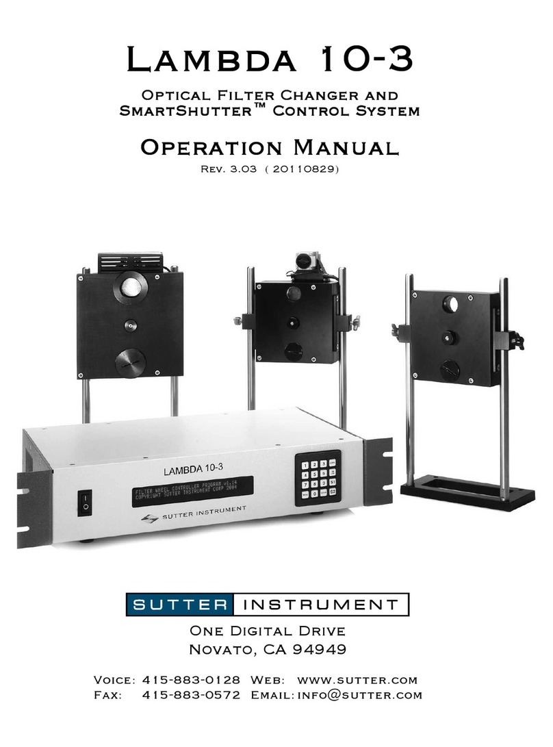
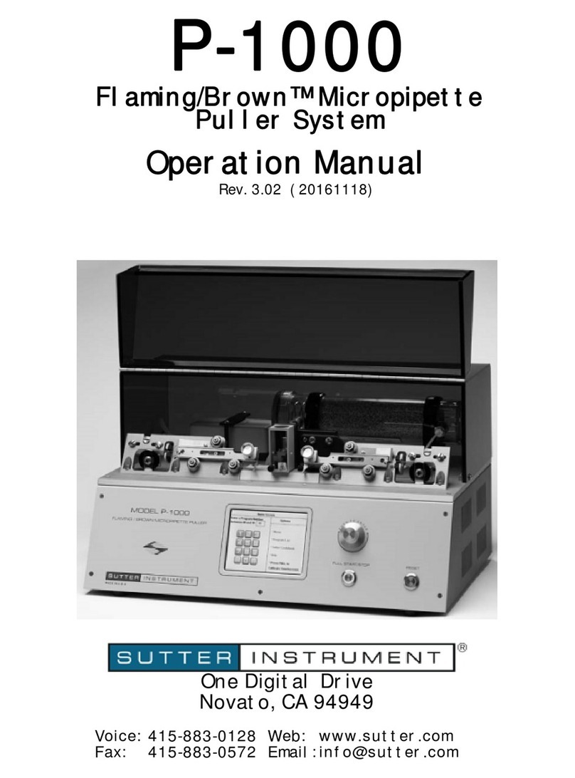
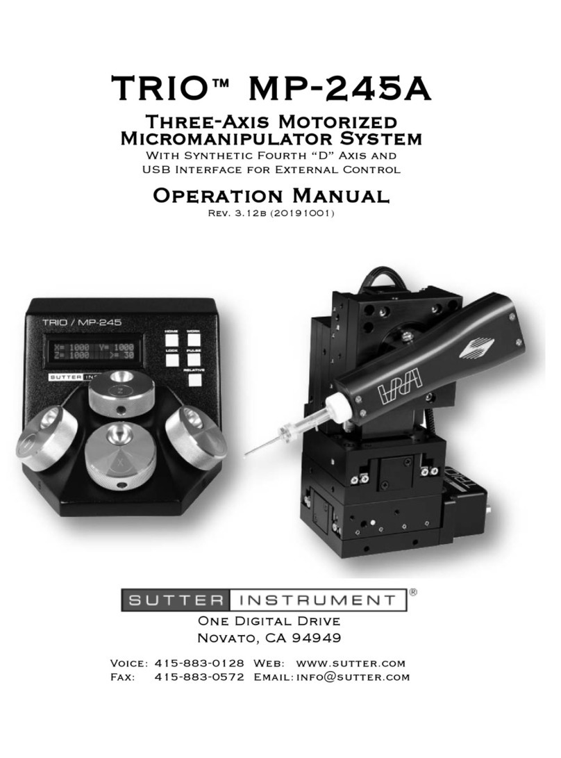
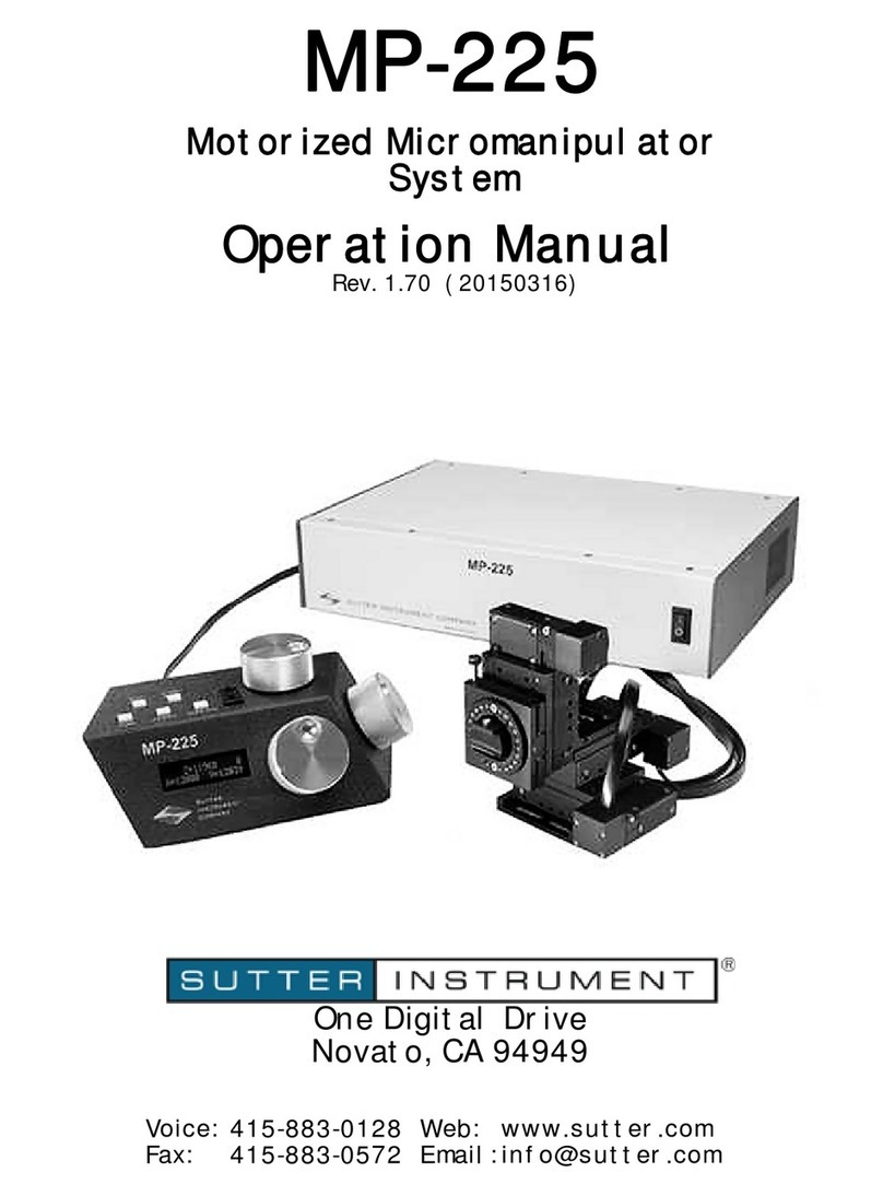
Sutter Instrument XenoWorks BRM User manual

XenoWorks®BRM
Motorized Micromanipulator
System
(TouchDeclutch)
Operation Manual
Rev. 4.10 ( 20141208)
Sutter Instrument Company
One Digital Drive
Novato, CA 94949
Voice: 415-883-0128 Web: www.sutter.com
Fax: 415-883-0572 Email: info@sutter.com

XENOWORKS MICROMANIPULATOR SYSTEM (TOUCHDECLUTCH) OPERATION MANUAL – REV.
ii
Copyright © 2015 Sutter Instrument Company. All Rights Reserved.
XenoWorks®is a registered trademark of Sutter Instrument Company.
4.10 (20141208)


4.10 20141208( )
iii
DISCLAIMER
The XenoWorks®BRM Micromanipulator is designed for the specific use of moving
micropipettes in three-dimensional space in increments of micrometers into and out of an
optical pathway of a microscope and no other use is recommended.
This instrument is designed for use in a laboratory environment. It is not intended for use,
nor should it be used, in human experimentation or applied to humans in any way. This is
not a medical device.
Do not open or attempt to repair the instrument. Extreme heat and high voltages are
present and could cause injury.
Do not allow unauthorized and/or untrained operative to use this device.
Any misuse will be the sole responsibility of the user/owner and Sutter Instrument Company
assumes no implied or inferred liability for direct or consequential damages from this
instrument if it is operated or used in any way other than for which it is designed.
SAFETY WARNINGS AND PRECAUTIONS
Electrical
Operate the XenoWorks BRM using 110-120 V AC, 60 Hz, or 220-240 V AC., 50 Hz line
voltage. This instrument is designed for connection to a standard laboratory power outlet
(Overvoltage Category II), and because it is a microprocessor--controlled device, it should
be accorded the same system wiring precautions as any 'computer type' system. A surge
protector and power regulator are recommended.
Fuse Replacement: Replace fuse only with the same type and rating as indicated in
the following table.
Fuse
(Type: Time Delay, 5mm x 20mm, glass tube)
Mains Voltage Setting
Rating Manufacturer Examples
“110” (100 – 120 VAC) 2A, 250V (Time
Delay)
Bussmann: GMC-2A, GMC-2-R (RoHS),
GDC-2A, or S506-2A (RoHS)
Littelfuse: 239 002 or 239.002.P (RoHS)
“220” (200 – 240 VAC) T1.0A, 250V Bussmann: GDC-1A or S506-1A (RoHS)
Littelfuse: 218 001 or 218 001.P (RoHS)
A spare fuse is located in the power input module. Please refer to the fuse-replacement
appendix for more details on fuse ratings and for instructions on how to change the fuse.
Avoiding Electrical Shock and Fire-related Injury
Always use the grounded power supply cord set provided to connect the system to a
grounded outlet (3-prong). This is required to protect you from injury in the event that
an electrical hazard occurs.
Do not disassemble the system. Refer servicing to qualified personnel.
XENOWORKS MICROMANIPULATOR SYSTEM (TOUCHDECLUTCH) OPERATION MANUAL – REV.

4.10 20141208( )
i
v
To prevent fire or shock hazard do not expose the unit to rain or moisture.
Electromagnetic Interference
To comply with FDA and CE electromagnetic immunity and interference standards; and to
reduce the electromagnetic coupling between this and other equipment in your lab always
use the type and length of interconnect cables provided with the unit for the interconnection
of the controller with the manipulator mechanical and with the joystick (see the
TECHNICAL SPECIFICATIONS appendix for more details).
Operational
Failure to comply with any of the following precautions may damage this device.
This instrument is designed for operation in a laboratory environment (Pollution Degree
I) that is free from mechanical vibrations, electrical noise and transients.
This unit is not designed for operation at altitudes above 2000 meters nor was it tested
for safety above 2000 meters.
Before making electrical connections, ensure that the instrument is switched off.
DO NOT CONNECT OR DISCONNECT THE CABLES BETWEEN THE
CONTROLLER AND THE MECHANICAL UNITS WHILE POWER IS ON.
Please allow at least 20 seconds after turning the unit off before disconnecting the
mechanical units. Failure to do this may result in damage to the electronics.
Operate this instrument only according to the instructions included in this manual.
Do not operate if there is any obvious damage to any part of the instrument.
Operate only in a location where there is a free flow of fresh air on all sides.
NEVER ALLOW THE FREE FLOW OF AIR TO BE RESTRICTED.
Do not operate this instrument near flammable materials. The use of any hazardous
materials with this instrument is not recommended and if undertaken is done so at the
users’ own risk.
Do not attempt to operate the instrument with the manipulator shipping screws in
place - severe motor damage may result.
Do not operate if there is any obvious damage to any part of the instrument. Do not
attempt to operate the instrument with the manipulator shipping screws in place - severe
motor damage may result. When transporting the mechanical manipulator, be sure to
install the shipping screws supplied in their correct locations. Failure to do this may
result in damage to the motors.
Never touch any part of the micromanipulator electromechanical device while it is in
operation and moving. Doing so can result in physical injury (e.g., fingers can be caught
and pinched between the moving parts of the micromanipulator).
XENOWORKS MICROMANIPULATOR SYSTEM (TOUCHDECLUTCH) OPERATION MANUAL – REV.

v
As with all microinjection devices, sharp micropipettes can fly out of their holder
unexpectedly. Always take precautions to prevent this from happening. Never loosen the
micropipette holder chuck when the tubing is pressurized, and never point micropipette
holders at yourself or others. Always wear safety glasses when using sharp glass
micropipettes with pressure microinjectors.
Do not handle the manipulator mechanical while the power is on, and take care to
ensure no cables pass close to the mechanical manipulator.
Sutter Instrument recommends that the operator touch the microscope equipment
base (to discharge any static electricity) prior to using the XenoWorks BRM
Micromanipulator system.
Other
Use this instrument only for microinjection purposes in conjunction with the procedures
and guidelines in this manual.
Retain the original packaging for future transport of the instrument.
Some applications, such as piezo-impact microinjection call for the use of mercury in the
micropipette tip. The use of any hazardous materials with any Sutter Instrument’s
instrument is not recommended and if undertaken is done so at the users’ own risk.
When transporting the mechanical manipulator, be sure to install the shipping screws
supplied in their correct locations. Failure to do this may result in damage to the motors.
This instrument contains no user-serviceable components — do not open the instrument
casing. This instrument should be serviced and repaired only by Sutter Instrument or an
authorized Sutter Instrument servicing agent.
Sutter Instrument reserves the right to change specifications without prior notice.
This device is intended only for research purposes.
Do not carry the joystick by its joystick paddle, since damage may result.
Handling Micropipettes
Failure to comply with any of the following precautions may result in injury to the users
of this device as well as those working in the general area near the device.
The micropipettes used with this instrument are very sharp and relatively fragile.
Contact with the pulled micropipette tips, therefore, should be avoided to prevent
accidentally impaling yourself.
Always dispose of micropipettes by placing them into a well-marked, spill-proof “sharps”
container.
XENOWORKS MICROMANIPULATOR SYSTEM (TOUCHDECLUTCH) OPERATION MANUAL – REV. 4.10 20141208( )

4.10 20141208( )
vi
(This page intentionally left blank.)
XENOWORKS MICROMANIPULATOR SYSTEM (TOUCHDECLUTCH) OPERATION MANUAL – REV.

4.10 20141208( )
vii
TABLE OF CONTENTS
DISCLAIMER .........................................................................................................................................iii
SAFETY WARNINGS AND PRECAUTIONS ....................................................................................iii
Electrical .................................................................................................................................................iii
Avoiding Electrical Shock and Fire-related Injury.............................................................................iii
Electromagnetic Interference ...............................................................................................................iv
Operational .............................................................................................................................................iv
Other ........................................................................................................................................................ v
Handling Micropipettes.......................................................................................................................... v
1. GENERAL INFORMATION..............................................................................................................1
1.1 Introduction.......................................................................................................................................1
1.2 About This Manual...........................................................................................................................1
1.3 Technical Support.............................................................................................................................1
1.4 Product Description..........................................................................................................................1
1.4.1 Packing List ................................................................................................................................1
1.4.2 Joystick Controls and Features ................................................................................................2
1.4.2.1 X- and Y-Axis Control .........................................................................................................3
1.4.2.2 Y-Axis On/Off .......................................................................................................................4
1.4.2.3 Z-Axis Control ......................................................................................................................4
1.4.2.4 Joystick Declutch Mechanism............................................................................................4
1.4.2.5 Height Adjustment..............................................................................................................4
1.4.2.6 Joystick Tension Ring.........................................................................................................4
1.4.2.7 ‘Work’ Position ....................................................................................................................5
1.4.2.8 ‘Home’ Position ...................................................................................................................5
1.4.2.9 Speed.....................................................................................................................................5
1.4.2.10 ‘Z-floor’ ...............................................................................................................................5
1.4.2.11 Micropipette Holder Clamp..............................................................................................5
1.4.2.12 Swing Gate .........................................................................................................................6
1.4.3 Additional Features and Functions..........................................................................................6
1.4.3.1 ‘Setup’ ...................................................................................................................................6
1.4.3.2 Axis Polarity.........................................................................................................................7
2. INSTALLATION .................................................................................................................................9
3. OPERATING INSTRUCTIONS......................................................................................................13
3.1 General.............................................................................................................................................13
3.1.1 Moving the Micropipette with the Joystick...........................................................................13
3.1.2 Centering the Micropipette with Respect to the Joystick....................................................13
3.1.3 Setting the Angle of Approach of the Micropipette..............................................................14
3.1.3.1 Microinjection Chamber ...................................................................................................14
3.1.3.2 Applications and Suggested Setups .................................................................................14
3.1.3.3 Micropipette Type .............................................................................................................16
3.1.3.4 Working Distance ..............................................................................................................16
3.1.3.5 Piezo Impact Drive ............................................................................................................16
3.1.4 Memorizing the ‘Work’ Position ............................................................................................16
3.1.5 Using the ‘Home’ Function.....................................................................................................16
XENOWORKS MICROMANIPULATOR SYSTEM (TOUCHDECLUTCH) OPERATION MANUAL – REV.
4.10 20141208( )
viii
3.1.6 Cleaning the Micropipette.......................................................................................................17
3.1.7 Changing the Working Range of Movement.........................................................................17
3.1.7.1 Setting a ‘Z-Floor’..............................................................................................................17
3.1.8 Exchanging the Micropipette..................................................................................................18
3.2 Starting a Microinjection Session .................................................................................................18
3.2.1 Setting up the Microscope .......................................................................................................18
3.2.2 Setting up the Micromanipulator...........................................................................................18
4. MAINTENANCE...............................................................................................................................21
4.1 General.............................................................................................................................................21
4.2 Troubleshooting ..............................................................................................................................21
4.3 Transporting the Micromanipulator ............................................................................................25
APPENDIX A. LIMITED WARRANTY ..............................................................................................27
APPENDIX B. ACCESSORIES............................................................................................................29
Extensions..............................................................................................................................................29
Rotating Base.........................................................................................................................................29
Mounts ...................................................................................................................................................29
Adapters .................................................................................................................................................29
Holders ...................................................................................................................................................29
APPENDIX C. FUSE REPLACEMENT.............................................................................................31
APPENDIX D. TECHNICAL SPECIFICATIONS.............................................................................33
INDEX ....................................................................................................................................................37
TABLE OF FIGURES
Figure 1-1. Components of the XenoWorks micromanipulator. ........................................................... 2
Figure 1-2. Joystick. ................................................................................................................................... 3
Figure 1-3. The rear panel of the joystick. ............................................................................................... 3
Figure 1-4. Joystick height adjustment.................................................................................................... 4
Figure 1-5. Manipulator Mechanical. ....................................................................................................... 6
Figure 1-6. Close up of axis polarity switches.......................................................................................... 7
Figure 2-1. Mounting the right-handed manipulator to the far left corner of the adapter plate. ..... 9
Figure 2-2. Engaging the manipulator base plate in the microscope adaptor. .................................. 10
Figure 3-1. Location of LED and declutch touch band......................................................................... 13
Figure 3-2. Micropipette alignment controls. ........................................................................................ 14
Figure 3-3 (a and b). Suggested approach for suspended cells with angled micropipettes (ICSI,
Stem Cell, Nuclear Transfer). ............................................................................................... 15
Figure 3-4 (a and b). Suggested approach for suspended cells with straight micropipettes
(Pronuclear Injection). ........................................................................................................... 15
Figure 3-5 (a and b). Suggested approach for adherent cells rand straight pipettes. ....................... 15
XENOWORKS MICROMANIPULATOR SYSTEM (TOUCHDECLUTCH) OPERATION MANUAL – REV.
4.10 20141208( )
i
x
Figure C-1. Fuse replacement. ................................................................................................................ 31
TABLE OF TABLES
Table A-1. Mains fuse type and ratings................................................................................................. 11
Table C-1. Mains fuse type and ratings................................................................................................. 31
Table D-1. Speed settings and ranges of movement............................................................................. 33
Table D-2. Mains fuse type and ratings. ............................................................................................... 34
Table D-3. XenoWorks BRM Controller cables and receptacles/connectors...................................... 34
XENOWORKS MICROMANIPULATOR SYSTEM (TOUCHDECLUTCH) OPERATION MANUAL – REV.
XENOWORKS MICROMANIPULATOR SYSTEM (TOUCHDECLUTCH) OPERATION MANUAL – REV. 4.10 (20141208)
x
(This page intentionally left blank.)

4.10 20141208( )
1
1. GENERAL INFORMATION
1.1 Introduction
1.2 About This Manual
The XenoWorks Micromanipulator is a manipulator system comprised of three basic parts:
the controller (BRM), manipulator mechanical (MP-285/M), and joystick.
In the next, few pages you will find a product description to help you become acquainted with
operation, followed by installation instructions, and then detailed operating instructions.
Please take the time to read these instructions to assure the safe and proper use of this
instrument.
This manual is continually being updated. If you encounter any areas you feel should be
covered in expanded detail we would like to hear from you. Please contact our Technical
Support staff with your suggestions (415-883-0128 or info@sutter.com).
1.3 Technical Support
Unlimited technical support is provided by Sutter Instrument Company at no charge to our
customers. Our technical support staff is available between the hours of 8:00 AM and 5:00
PM (Pacific Time) at (415) 883-0128. You may also E-mail your queries to info@sutter.com.
1.4 Product Description
NOTE: Unless otherwise noted, all references to the manipulator mechanical are for the
right-handed version.
1.4.1 Packing List
The XenoWorks™ Micromanipulator is shipped with the following components:
1. Manipulator mechanical
2. Controller
3. Joystick
4. Manipulator mechanical base plate
5. Mains power cord
6. Cable for connecting the manipulator mechanical with the controller
7. Cable for connecting joystick with the controller
8. Instruction manual
9. Manipulator mechanical mounting screws (4)
10. Hex key (for manipulator mechanical mounting screws)
If any items are missing or appear damaged, contact Sutter Instrument or your dealer/rep
immediately.
XENOWORKS MICROMANIPULATOR SYSTEM (TOUCHDECLUTCH) OPERATION MANUAL – REV.
4.10 20141208( )
2
Figure 1-1. Components of the XenoWorks micromanipulator.
1.4.2 Joystick Controls and Features
The user interface of the XenoWorks™ Micromanipulator is a three-axis joystick. When the
micromanipulator is installed correctly, the joystick oriented appropriately on the working
surface, and the default axis polarity settings used (see “Axis Polarity”), a displacement of the
joystick to the left, for example, will result in concomitant movement of the
micromanipulator to the left. The movement of the micromanipulator is directly proportional
to the movement of the joystick, however the movement reduction ratio between the joystick
and the mechanical can be varied (see “Range” below).
XENOWORKS MICROMANIPULATOR SYSTEM (TOUCHDECLUTCH) OPERATION MANUAL – REV.
4.10 20141208( )
3
Figure 1-2. Joystick.
Figure 1-3. The rear panel of the joystick.
1.4.2.1 X- and Y-Axis Control
Movements of the micromanipulator in the X- and Y-axes are achieved by moving the joystick
left and right, and forward and backward, respectively (the switches for establishing axis
polarity for right- and left-handed manipulator mechanicals are located on the back of the
joystick).
XENOWORKS MICROMANIPULATOR SYSTEM (TOUCHDECLUTCH) OPERATION MANUAL – REV.
4
1.4.2.2 Y-Axis On/Off
The Y-axis can be turned off to produce pure X-axis travel. This results in a mode that may be
preferred for difficult injections/transfers, or when the cell or egg is more sensitive to the
withdrawal of the pipette.
1.4.2.3 Z-Axis Control
Movement of the micromanipulator in the Z-axis (vertical) is achieved by rotating the control
on the end of the joystick. Looking down on the joystick from above, and using the default
axis settings, a rotation of the Z-control in a clockwise direction will cause the
micromanipulator to move downwards. A counterclockwise rotation will result in an upward
movement of the micromanipulator.
1.4.2.4 Joystick Declutch Mechanism
The electronic link between the joystick and the manipulator mechanical can be disconnected
temporarily in order to reposition the joystick without affecting the position of the
micropipette. This declutch function is achieved by touching the joystick just above the
rubber handgrip - the X and Y movement will remain deactivated for as long as your finger is
touching the band. The link is reestablished by releasing the touchpad. See Operating
Instructions for more details on how to use the declutch.
1.4.2.5 Height Adjustment
To maintain good ergonomics and operator comfort, the height of the joystick can be
adjusted, as shown in the figure below. The bottom of the joystick can be placed anywhere
from zero to 45 mm above the black hand-rest pad. The adjustment is made by first loosening
the black locking knob located on the front of the joystick column. Move the joystick
assembly up and down along its vertical track until a comfortable position is achieved, and
then lock the position by tightening the locking knob.
Figure 1-4. Joystick height adjustment.
1.4.2.6 Joystick Tension Ring
There is a friction mechanism in the top of the joystick assembly allowing the X-Y movement
of the joystick to be adjusted for comfort and feel. The friction is reduced by rotating the
black dial clockwise (looking down from above) and increased by rotating counterclockwise.
XENOWORKS MICROMANIPULATOR SYSTEM (TOUCHDECLUTCH) OPERATION MANUAL – REV. 4.10 20141208( )

4.10 20141208( )
5
Although there is no recommended setting for this friction, it should be noted that if there is
no friction at all, the joystick would always fall to the center position under gravity, which
may not be desirable. Similarly, if the friction is set too tightly, the joystick may become too
stiff to use or may be locked in place and could be damaged if the dial is tightened further.
With a little practice, a suitable tension setting can be established.
1.4.2.7 ‘Work’ Position
The users’ ‘Work’ position can be designated as any position within the range of travel of the
micromanipulator. It is used primarily to ensure that the micropipette tip is not
inadvertently lost from the microscope field of view. It is recommended that the ‘Work’
position is refreshed at regular intervals during the course of an injection experiment. The
micropipette can be returned to the last position memorized by briefly touching the ‘Work’
key (See Operating Instructions).
1.4.2.8 ‘Home’ Position
Activation of the ‘Home’ function moves the mechanical to its outermost and uppermost
position, with respect to the microscope. The ‘Home’ position of a right-hand
micromanipulator will be all the way up and to the right and the ‘Home’ position of a left-
hand micromanipulator will be all the way up and to the left. It is for this reason that a right-
hand micromanipulator should not be used on the left side of the microscope and vice-versa.
The ‘Home’ position is a factory preset and cannot be re-configured. See Operating
Instructions for details.
1.4.2.9 Speed
The speed of the micromanipulator can be adjusted to accommodate different microscope
magnifications and the differing needs of operators and applications. There are six speed
settings corresponding to six different sensitivities of micromanipulator movement. See
Operating Instructions on how to set the desired movement range. Speed settings 1 and 2 are
good for locating pipette into field of view. Speeds 3, 4, and 5 are ideal for micromanipulation
and microinjection.
1.4.2.10 ‘Z-floor’
The ‘Z-floor’ is a function which allows the user to define a lower limit (or “floor”) of the Z-
axis travel of the micromanipulator. In practice, it is used to protect a micropipette from
being broken by preventing the user from crashing the micropipette into the bottom of the
microinjection chamber. The ‘Z-floor’ is described in more detail in the Operating
Instructions section.
1.4.2.11 Micropipette Holder Clamp
The micropipette holder clamp arrangement on the front of the mechanical is designed to
allow many different micropipette types to be used with the maximum stability possible. The
clamp can be adjusted for height, reach and angle of attack. See Operating Instructions for
details on setting the micropipette holder clamp for the optimum angle of attack of the
micropipette.
XENOWORKS MICROMANIPULATOR SYSTEM (TOUCHDECLUTCH) OPERATION MANUAL – REV.
6
1.4.2.12 Swing Gate
The swing gate on the front of the mechanical allows the micropipette to be swung out
toward the front of the microscope for better access when changing micropipettes. The gate
can be released by loosening the fixing screw. The screw should be tightened fully during use.
Figure 1-5. Manipulator Mechanical.
1.4.3 Additional Features and Functions
1.4.3.1 ‘Setup’
When the micropipette is aligned at the beginning of an experiment, the tip should be located
in the center of the microscope’s field of view and there should be as much movement range
as possible in both directions in each axis, X, Y and Z. The ‘Setup’ function has been designed
to easily achieve this and thus protect the user from inadvertently running out of motor
travel during an experiment. By following the instructions included in this manual, use of
the ‘Setup’ function will position each of the three axis motors in an optimal position to begin
working.
CAUTION: Use the Setup function only when there is no pipette and holder in the
manipulator.
The ‘Setup’ function should only be activated when there is sufficient space available around
the mechanical. Activating the ‘Setup’ function when the manipulator mechanical is too close
to a microscope component such as the condenser, may result in damage to the motor or the
microscope. Refer to Installation Procedure for details on the use of the ‘Setup’ function
during installation and Operating Instructions for details on routine use.
XENOWORKS MICROMANIPULATOR SYSTEM (TOUCHDECLUTCH) OPERATION MANUAL – REV. 4.10 20141208( )

4.10 20141208( )
7
1.4.3.2 Axis Polarity
Occasionally, it may be desirable to reverse the direction of one, two or all three motors so
that the movement of the joystick results in movement of the corresponding manipulator
mechanical in the opposite direction. An example of this would be the use of the manipulator
with an upright microscope where the image is inverted.
The axis polarity controls are located on the rear of the joystick column.
Each DIP-switch control affects one axis; switch 1 reverses the X-axis, switch 2 reverses the
Y-axis, and switch 3 reverses the Z-axis. The figure above illustrates the default axis polarity
settings for a left-hand (left image) and right-hand (right image) micromanipulator. Axis
polarities can be changed without having to power down the micromanipulator.
Figure 1-6. Close up of axis polarity switches.
XENOWORKS MICROMANIPULATOR SYSTEM (TOUCHDECLUTCH) OPERATION MANUAL – REV.

XENOWORKS MICROMANIPULATOR SYSTEM (TOUCHDECLUTCH) OPERATION MANUAL – REV.
8
(This page intentionally left blank.)
4.10 (20141208)
Table of contents
Other Sutter Instrument Laboratory Equipment manuals

Sutter Instrument
Sutter Instrument P-97 Installation manual

Sutter Instrument
Sutter Instrument TRIO MP-245A User manual

Sutter Instrument
Sutter Instrument LAMBDA 10-B User manual

Sutter Instrument
Sutter Instrument P2000/G User manual

Sutter Instrument
Sutter Instrument Lambda DG-4 User manual

Sutter Instrument
Sutter Instrument P-1000 User manual

Sutter Instrument
Sutter Instrument MP-225A User manual

Sutter Instrument
Sutter Instrument MP-225 User manual

Sutter Instrument
Sutter Instrument MT-75 Series User manual

Sutter Instrument
Sutter Instrument P-2000 User manual