Streetwize SWPP4 User manual
1. Check manufacturer’s specification on item to be inflated for correct inflation pressure.
2. Remove valve cap cover from valve stem.
3. Insert proper valve stem adapter into stem connector as far as possible and turn the locking thumb lever to down
position.
4. Insert other end of valve stem adapter into inflatable air valve stem as far as practical.
5. Set the compressor on/off switch to “on” position.
6. Monitor pressure on air pressure gauge. When desired pressure is reached, turn off compressor, turn the locking
thumb lever to up position and remove stem connector from valve stem. Also remove valve stem adapter if
applicable. Replace valve cap on valve stem.
STORAGE: This unit may be stored in any position. Make sure the clamps are secure inside the booster cable
storage covers. Store at room temperature. If not used for a prolonged period of time, recharge every 2 months in
the winter and every month in the summer.
SPECIFICATIONS
Battery: 12 volt 8AH sealed lead acid, maintenance free, spill-proof, rechargeable.
Power Supply DC Output: 12-volts nominal. Up to 10 Amps with auto reset protector
Power Supply Charging Time: 24 hours with AC charger;
6 hours to recharge with 12-volt DC charger.
Storage Temperature: Store in a cool dry area.
The WEEE symbol on this product means that this product should be ethically dismantled or recycled to
minimise environmental impact. Please check with your local authority for more information.
IMPORTANT: ADDITIONAL SAFETY INFORMATION
This Power Station/Emergency Jumpstart is NOT intended for use by persons (including children) with reduced
physical, sensory or mental capabilities, or lack of experience and knowledge, unless they are supervised or
have been given instruction concerning use of the Power Station/Emergency Jumpstart by a person responsible
for their safety.
EC DECLARATION OF CONFORMITY
In accordance with EN ISO 170504:2004
We; The Ace Supply Co Ltd., T/A Streetwize Accessories
Of; Unit 9, Warth Rd Ind Estate, Warth Road, Bury,Lancashire BL9 9NB
And in accordance with the following Directive(s):
2004/108/EC The Electromagnetic Compatibility Directive
2006/42/EC The Machinery Directive
hereby declare that: SWPP4 - Power Station with Air Compressor
is in conformity with the applicable requirements of the following directives:
EN55014-1:2006, EN55014-2:1997+A1:2001, EN55015:2006+A1:2007, EN61541:1995+A1:2000,
EN61000-3-2:2006, EN61000-3-3:2008, EN61558-1:1997+A1:1998+A11:2003, EN61558-2-4:1997,
EN61558-2:17:1997, EN60950-1:2006, EN60335-1:2002+A1:2004+A2:2006+A11:2004+A12:2006
2011/65/EU Verification Testing Of Restriction Of hazardous Substances (ROHS)
Signed by: Name: Antony Collier - QC Manager
Signed at Bury on 18/12/12
12v Portable Power Station & Emergency
Jumpstarter with Air Compressor
SWPP4
• High Impact Resistant Rubberized Housing • 300 AMP Jump Start System
• Reverse Polarity Indicator • 260 PSI Air Compressor with Pressure Reading Gauge
• 12 Volt Power Station
WELCOME: This product has been carefully engineered and manufactured to give you dependable operation.
Please read this manual thoroughly before operating your new product as it contains the information you need to
become familiar with its features and obtain the performance that will bring you continued enjoyment for many
years. Please keep this manual on file for future reference.
IMPORTANT: PRIOR TO USE, READ AND UNDERSTAND ALL WARNINGS, CAUTIONS AND INSTRUCTIONS INCLUDED
IN THIS INSTRUCTION MANUAL, AND THOSE PUBLISHED BY YOUR VEHICLE BATTERY MANUFACTURER AND
MANUFACTURER OF ANY DEVICE INTENDED TO BE USED WITH THIS UNIT. RETAIN THESE INSTRUCTIONS FOR
FUTURE REFERENCE.
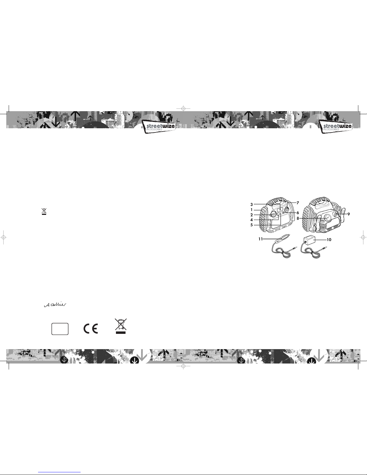
LOCATION OF CONTROLS
1. High Impact Resistant
Rubberized Housing
2. Jump Start System Power Switch
3. Reverse Polarity Indicator
4. Battery Status Check Button
5. Battery Status Indicator
6. Charging Jack
7. 12 Volt Power Outlet
8. 260PSI Pressure Reading Gauge
9. Air Compressor On/Off Switch
10. AC Charger
11. DC Charger
FIRST AID: Make sure fresh water and soap are available nearby in case battery acid contacts skin, eyes or
clothing. If contact with battery acid occurs, rinse immediately and thoroughly with water. Then wash with soap and
water. Obtain immediate medical attention if redness, irritation or pain is present. For eye contact, flush eyes for at
least 15 minutes and obtain immediate medical attention.
CAUTIONS
• Never work alone with this product. Make sure that someone is available to give assistance if needed.
• Wear complete eye and clothing protection. Do not touch eyes while working near battery.
• Do not attempt to remove or replace the battery used in this device. When the battery has reached the
end of it’s useful lifetime, take the entire unit to a battery recycling facility.
• For proper and safe operation of the 12 Volt DC power accessory outlets, do not place anything into it
except the plug of the accessory to be used.
• Remove metal personal jewelry, such as rings, bracelets, necklaces and watches while working with a
lead-acid battery. It can produce a short-circuit that may cause severe burns.
• Never charge or jump-start a frozen battery.
• Never allow clamps (positive & negative terminals) to touch together or to connect the same piece of
metal to prevent short-circuits and arcing.
• Do not operate this device while wearing vinyl clothing. Static electricity may be generated when vinyl
clothing is rubbed.
• This product is not intended for use in the rain or temperatures above 130˚F.
• Use only the provided chargers, cables and clamps. Unauthorized parts may damage the unit.
• This product is not a toy. Keep out of the reach of children.
• Keep battery terminals clean. Be careful to keep corrosion from coming in contact with eyes.
RoHS
COMPLIANT
Lancashire
BL9 9NB
SWPP4 Manual AW:Layout 1 15/3/15 11:17 Page 1
6. Never allow clamps (positive & negative terminals) to touch together or to contact the same piece of metal to
prevent short-circuits and arcing.
7. Follow instructions for a negative grounded system or positive grounded system as indicated below:
Negative Grounded System:
a. Securely connect the positive (+) red clamp to the positive (POS, P+) terminal of the vehicle battery or the
remote positive (+) terminal if equipped.
b. Check that vehicle is negatively grounded (most vehicles). Securely connect the negative (-) black clamp to the
vehicle chassis, engine block or a non- moving metal part of the vehicle which is verified to be grounded. Do not
clamp directly to negative battery terminal, carburetor, fuel lines, or sheet metal body parts. Check cable
connection polarity indicator.
c. See jump-starting step 7 to continue.
Positive Grounded System:
a. Securely connect the negative (-) black clamp to the negative (Neg, N-) ungrounded terminal of the vehicle
battery.
b. Securely connect the positive (+) red clamp to the vehicle chassis, engine block or a non-moving metal part of
the vehicle which is verified to be grounded. Do not clamp directly to positive battery terminal, carburetor, fuel
lines, or sheet metal body parts.
c. See jump-starting step 7 to continue.
8. The Reverse Polarity Indicator on the Jump Starter will illuminate RED for wrong connection and GREEN for right
connection.
9. When correct clamp connection is made, turn the Jump Start System Power Switch to ON position.
10. Allow 2 or 3 minutes of charging time. It is recommended to have a second person to assist holding the unit
securely in place during the next steps.
11. Turn on the vehicle to attempt to start the engine. If the vehicle does not start after 4 to 5 seconds of engine
cranking, then stop. Wait 3 to 4 minutes, and then try again. Repeat several times until the vehicle starts.
12. Standing as far away from the vehicle battery as is practical, disconnect the clamps in reverse sequence to
connecting procedure:
For negative grounded systems, first disconnect negative (black) then positive (red) clamps.
For positive grounded systems, first disconnect positive (red) then negative (black) clamps.
USING THE AIR COMPRESSOR:
To inflate tires:
1. Remove valve cap from air valve stem. Note: Make sure locking thumb lever is at up position. If necessary, use
valve stem adapter.
2. Insert stem connector to valve stem. Make sure connector is pushed on to valve stem as far as possible.
3. Press down the locking thumb lever to engage.
4. Set the compressor on/off switch to “on” position by pressing down the section of switch marked “I”. Note: In
the event that the tire is completely flat, raise the vehicle using a recommended jack before inflating the tire.
5. Monitor pressure on air pressure gauge.
6. When desired pressure is reached, turn off compressor.
Turn the locking thumb lever to up position and remove stem connector from valve stem. Also remove valve stem
adapter if applicable.
7. Replace valve cap on valve stem.
To inflate plastic inflatable (balls, air mattresses, rubber rafts, etc.):
WARNING: Check item to be inflated for manufacturer’s maximum recommended inflation pressure.
Avoid over inflation. Most tires are properly inflated between 24-35 PSI. Some truck and bicycle tires
require 40 PSI or more.
• Do not operate this unit in or around water. Water can damage the unit.
• If battery acid comes into contact with eyes, flush the eyes with water for at least 10 minutes. Seek
medical attention immediately.
• Always turn the Jumpstart Sustem off when not in use. Store in a cool, dry place.
• Do not open the Jumpstart System. There are no servicable parts in the unit. Doing so will void the warranty.
CHARGING AND RECHARGING
• Fully recharge the unit when red charge indicator light is on.
• The charging Red LED indicator will be illuminated while charging. When charging is complete the Red LED
changes to Green. This LED will not go out until the charging plug is removed.
• Do not charge the unit for more than 36 hours by AC charger and 12 hours by DC charger continuously.
• Do not charge the unit on a boat, boat ramp, or dock since the electrical cords and outlets used for charging could
cause severe electrical shock if they get wet.
• It is recommended that the unit be in an upright position while charging.
NOTE: Make sure both cable clamps (positive and negative) are placed in their storage holsters when not
in use.
CHARGING WITH AC CHARGER:
1. Press the battery status check button, if the battery status Green LED illuminates it will indicate a full charge.
2. If the SWPP4 requires charging, insert AC charger plug into charging jack of the unit.
3. Insert AC charger receptacle plug into AC receptacle.
4. The battery status Red LED will illuminate while charging.
5. Full charge takes approximately 24 hours.
6. The Red LED changes to Green, when charging is complete, unplug the AC charger receptacle plug then the
AC charger from the charging jack on the unit.
CHARGING WITH 12-VOLT CHARGER:
1. Press the battery status check button, if the battery status Green LED illuminates it will indicate a full charge.
2. If the SWPP4 requires charging, insert DC charger plug into charging jack of the unit.
2. Insert DC charger accessory plug into vehicle cigarette lighter socket.
3. The battery status Red LED will illuminate while charging.
4. Full charge takes approximate 6 hours, while the car engine is running.
5. The Red LED changes to Green, when charging is complete, unplug the DC charger accessory plug first and then
the DC charger from the charging jack on the unit.
JUMP-STARTING A VEHICLE
1. Turn off the vehicle ignition and all accessories (e.g. radios, lights, air conditioners and cellular phones).
2. Set the emergency brake and put vehicles with automatic transmission in park position.
3. Make sure the Jump Start System Power Switch is in OFF position.
4. Determine the polarity of the vehicle’s battery terminals. The positive (POS, P, +) battery terminal usually is larger
in diameter than the negative (NEG, N, -) terminal. If you are unsure, you should refer to the vehicle’s owner’s
manual.
5. Determine whether your vehicle uses a negative or positive grounded system: Negative ground system – Negative
battery terminal is grounded to chassis. Most vehicles use this system.
Positive grounded battery terminal is grounded to chassis or any other part of the vehicle. If you are unsure, you
should refer to vehicle owner’s manual.
WARNING: Do not overcharge this unit. Prior to charging unit, read and understand all instructions for
this unit. Overcharging may result in damage to the unit.
IMPORTANT WARNING: This product is only supplied with a minimal amount of charge at manufacture,
therefore for this product to operate correctly it has to be fully charged for a period of 24 hours
IMMEDIATELY after purchase, this is essential BEFORE ANY USE! & cannot be used DURING the charge
period. Failure to adhere to these conditions may invalidate the products warranty.
SWPP4 Manual AW:Layout 1 15/3/15 11:17 Page 3
Other Streetwize Remote Starter manuals

Streetwize
Streetwize SWPP14 User manual

Streetwize
Streetwize SWPP5 User manual

Streetwize
Streetwize SWPP20 Specification sheet

Streetwize
Streetwize SWPP2 User manual

Streetwize
Streetwize SWPP17 User manual

Streetwize
Streetwize SWPB1 User manual

Streetwize
Streetwize SWPP1 User manual

Streetwize
Streetwize SWPP3 User manual

Streetwize
Streetwize SWPB1 User manual
Popular Remote Starter manuals by other brands


Linear
Linear Digital Keyless Entry System Installation and programming instructions

Berner
Berner 338991 owner's manual

Spartan
Spartan Ultimaster Purolator Service manual

EverStart
EverStart maxx EL224 owner's manual

Omegalink
Omegalink OL-RS-NI5 install guide

Mazda
Mazda 0000-8F-Z80 installation instructions


