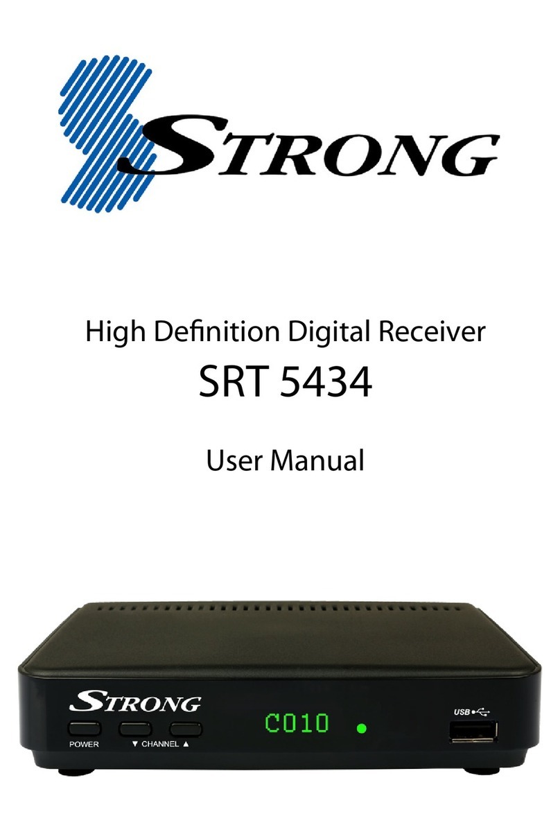
Strong SRT 5390 User manual

SRT-5390
FREE-TO-AIR
DIGITAL TERRESTRIAL PVR RECEIVER
USER’S MANUAL
5390
E109000197A
STRONG&Co. (FAR EAST), LTD.
P. O. Box:85, YOKOHAMA, KANAGAWA-KEN
JAPAN 231-91 -FAX:+81 45 662-4957
Website:www.strong-technologies.com
E-mail:[email protected]

IMPORTANT SAFETY INSTRUCTIONS
All the safety and operating instructions should be read
before the product is operated.
The safety and operating instructions should be
retained for future reference.
All warnings on the product and in the operating
instructions should be adhered to.
All operating and using instructions should be followed.
Unplug this product from the wall outlet before
cleaning.
Do not use liquid cleaners or aerosol cleaners, Use
damp cloth for cleaning.
Do not use attachments not recommended by the
product manufacturer as they may cause hazards.
Do not use this product near water - for example, near a
bath tub, wash bowl, kitchen sink or laundry tub; in a
wet basement; or near swimming pool; and the like.
Do not place this product on an unstable cart, stand,
tripod, bracket, or table, The product may fall, causing
serious injury to a child or an adult and serious damage
to the product. Use only with a cart, stand, tripod,
bracket, or table recommended by the manufacturer, or
sold with the product. Any mounting of the product
should follow the manufacturer’s instructions, and
should use a mounting accessory recommended by the
manufacturer.
A product and cart combination should be moved with care. Quick stops, excessive forces
and uneven surfaces may cause the product and cart combination to overturn.
WARNING
To prevent fire or shock hazard, do not expose
the unit to rain or moisture.
AVIS
POUR EVITER LE RISQUE D’INCENDIE OU CHOC ELECTRIQUE-NE
PAS EXPOSER L’APPAREIL A LA PLUIE OU LA MOITEUR
ATTENTION : RISQUE CHOC LELECTRIQUE-NE
PAS OUVRIR
CAUTION : TO REDUCE THE RISK OF ELECTRIC SHOCK
DO NOT REMOVE COVER (OR BACK).
NO USER SERVICEABLE PARTS INSIDE
REFER SERVICING TO QUALIFIED SERVICE PERSONNEL
RISK OF ELECTRIC SHOCK,
DO NOT OPEN
This symbol is intended to alert the user to the
presence of uninsulated "dangerous voltage"
within the product's enclosure that may be of
sufficient magnitude to constitute a risk of electric
shock to persons.
This symbol is intended to alert the user to the
presence of important operating and
maintenance(servicing) instructions in the
literature accompanying the appliance.
CAUTION : TO PREVENT ELECTRIC SHOCK. MATCH
WIDE BLADE OF PLUG TO WIDE SLOT,
FUSE INSERT.
ATTENTION : POUR ÉVITER LES CHOC ÉLECTRIQUES.
INTRODURE LA LAME LA PLUS LARGE
DE LA FICHE DANS LA BORNE
CORRESPONDANTE ED LA PRISE ET
POUSSER JUSOU’AU FOND.
NOTE TO CATV SYSTEM INSTALLER : THIS REMINDER
IS PROVIDED TO CALL THE CATV SYSTEM
INSTALLER’S ATTENTION TO ARTICLE 820-40 OF THE
NEC THE PROVIDES GUIDELINES FOR PROPER
GROUNDING AND, IN PARTICULAR, SPECIFIES THAT
THE CABLE GROUND SHALL BE CONNECTED TO
THE GROUNDING SYSTEM OF THE BUILDINGS AS
CLOSE TO THE POINT OF CABLE ENTRY AS
PRACTICAL.
Slots and openings in the cabinet are provided for ventilation and to ensure reliable operation of the product and to protect
it from overheating, and these openings must not be blocked or covered. The openings should never be blocked by placing
the product on a bed, sofa, rug, or other similar surface. The openings should not be placed in a built-in installation such as
a bookcase or rack unless proper ventilation is provided or the manufacturer's instructions have been adhered to.
This product should be operated only from the type of power source indicated on the marking label. If you are not sure of
the type of power supply to your home, consult your product dealer or local power company. For porducts intended to
operate from battery power, or other sources, refer to the operating instructions.
This product may be equipped with a polarized alternating-current line plug(a plug having one blade wider than the other).
This plug will fit into the power outlet only one way. This is a safety feature. If you are unable to insert the plug fully into the
outlet, try reversing the plug. If the plug should still fail to fit, contact your electrician to replace your obsolete outlet. Do
not defeat the safety purpose of the polarized plug.
Power supply cord should be routed so that they are not likely to be walked on or pinched by items placed upon or against
them, paying particular attention to cords at plugs, convenience receptacles, and the point where they exit from the
product.
If an outside antenna or clable system is connected to the product, be sure the antenna or cable system is grounded so as
to porvide some protection against voltage surges and built-up static charges. Article 810 of the National Electrical Code,
ANSI/NFPA 70, provides information with regard to proper grounding of the mest and supporting structure, gorunding of
the lead-in wire to an antenna discharge unit, size of grounding conductors, location of antenna-discharge unit, connection
to grounding electrodes, and requirements for the grounding electrode.
For added protedtion for this product during a lighting storm, or when it is left unattecded and unused for long periods of
time, unplug it from the wall outlet and disconnect the antenna or cable system. This will prevent damage to the product
due to lightning and power-line surges.
An outside antenna system should not be located in the vicinity of overhead power lines or other electric light or power
circuits, or where it can fall into such power lines or circuits. When installing an outside antenna system, extreme care
should be tacken to keep from touching such power lines or circuits as contact with them might be fatal.
Do not overload wall outlets, extension cords, or integral convenience receptacles as this can result in a risk of fire or
electric shock.
Never push any kinds of objects into this product through openings as they may touch dangerous voltage points or short-
out parts that could result in a fire or electric shock. Never spill any kind of liquid on the product.
Unplug this product from the wall outlet and refer servicing to qualified service personnel under the following conditions:
When the power supply cord or plug is damaged.
If liquid has been spilled, or objects have fallen into the product.
If the product has been exposed to rain to water. If the product does not operate normally by following the operating
instructions. Adjust only those controls that are covered by the operating instructions as an improper adjustment of other
controls may result in damage and will often require extensive work by a qulaified technician to restore the product to its
normal operation.
If the product has been dropped or damaged in any way.
When the product exhibits a distinct change in performance - this indicates a need for service.
When replacement parts are required, be sure the service technician has used replacement part specified by the
manufacturer or have the same characteristics as the original part. Unauthorized subsitutions may result in fire, electric

shock, or other hazards.
Upon completion of any service or repair to this product, ask the service technician to perform safety checks to determine
that the product is in proper operating condition.
The product should be situated away from heat sources such as radiators, heat registers, stoves, or other
products(including amplifiers) that produce heat.

1
11. Introduction 2
1.1 Overview
1.2 Main Features
12. Safety/Precautions 3
2.1 Safety
2.2 Precautions
3. Check Point before Use 5
3.1 Accessories
14. Controls/Functions 6
4.1 Front Panel
4.2 Rear Panel
4.3 Remote Control unit
15. Using Remote Control unit 11
5.1 Batteries
5.2 Range Of Operation
16. How to Connect 13
17. Operation 16
7.1 Getting Started
7.2 Channel Editing
7.3 System Parameters
7.4 Manual Scan
7.5 Factory Set
7.6 Software Download
7.7 Other Function on Remote Control unit
18. Hard Disk Operation 68
8.1 Recording
8.2 Playing
8.3 Delete Programs
8.4 Lock Programs
8.5 Skip Play
8.6 Split Operation
8.7 Trick Play Controls without OSD
8.8 Direct Recoding & Pause
19. Trouble Shooting 83
10. Specifications 84

2
Fully compliant with MPEG-2 and DVB standards
User friendly operating Menu and On-Screen Graphic Menu
Easy to use EPG(Electronic Program Guide)on screen
Age protection lock function
Manual PID control
Software downloading via RS-232C connector
Tele-text encoding
Hard Disk Functions
This terrestrial receiver is designed for giving you the opportunity to enjoy digital
broadcasting. This receiver is a technical masterpiece, assembled with the highest
qualified electronic parts.

3
Be sure to read the user's manual before
starting the operation of the unit.
Never open the cover. It is very dangerous to
touch the inside of the unit due to possible
electric shock.
When you do not use this unit for a long time,
make sure that power cord is pulled out from
the outlet. Also do not use a damaged
power cord as it may cause fire or electric
shock.
Do not touch the power cord with wet hands
as it may cause electric shock.
A professional installation is required.
If reception is interrupted, contact your
local service centre.
Place the unit in a well ventilated and no-
heat environment.

4
When installing the unit
Install the unit horizontally. An uneven
installation may cause the unit to be
damaged.
Do not put heavy items such as a TV on the
unit. That may cause the unit to be
damaged.
Moving the unit to a hot area from a cold
one will cause condensation.
Do not operate the unit for one or two hours
or until it has dried completely.
Where it is subject to vibrations
Where it is exposed to direct sunlight
Where there is humidity
Where the temperature is too high or too low.
Where there is no ventilation
Do not install the unit:
Do not put water holding items shch as vase
on the unit.
Do not leave the unit where the water
drops or splashs.

5
User's manual : 1
User's manual
Remote control : 1
Batteries (AAA type) : 2
RF Cable(0.25M) : 1
RCA video/audio cable : 1
If any accessories listed above are
missing, contact the sales
representative where you purchased
this unit.
Accessories of the Unit
QZ-
ABC DEF
GHI JKL MNO
PRS TUV WXY
INFO
AUDIO
GUIDE
CH.LIST
AUX IN
RECALL
TV/RADIO
TV/STB
MENU
EXIT
CH
VOLVOL
CH

6
Power
To switch the receiver in “standby” mode or in power on mode.
Remote Sensor
Receives the infrared signal from remote control.
Channel Display(4 Digit)
- When you connect the power line of the receiver, the current time is displayed.
- After programming, the program number is displayed.
Menu
To launch or terminate the menu application.
Select
To activate a highlighted item or go to next level on hypertext menu or confirm the
user s action.
5
4
3
2
1
5390
1 2
4 5 6 9 7
3 8
11 1210

7
- Vol. /
To adjust the volume level or change the value of an item with preprogrammed
values. The Key can be used as a backspace to cancel the numerical input.
- CH. /
To change channel or cursor position on the application screen.
Remote Control indication light
Flashes orange when receiving data from remote control.
TV/Sat. mode Indication lamp light
Turn on green while receiving the signals from terrestrial UHF/VHF antenna.
Standby/Power on Indication light
Turn on red while in the “standby” mode and turn off the red light while in the power on
mode.
Slot A, B
PCMCIA-module : provided by a broadcaster for watching scrambled programs.
Smart Card Slot
Smart Card : provided by a broadcaster for watching IRDETO scrambled programs.
12
11
10
98
76

8
4
COAXIAL
RF LOOP IN
TV ANT
IN
RF LOOP
OUT
RS-232C
RF OUT
UHF 21-69
OPTICAL S-VIDEO
S/PDIF
1 2 3 5 7 9
10 12
6 8
11 13
No. Name Connector Function
1 DIGITAL AUDIO Optical port Digital audio output.
2 S-VIDEO S-Video jack S-Video output.
3 DIGITAL AUDIO RCA cinch Digital Audio Output.
4 TV SCART SCART SCART output to TV.
5 VCR/AUX SCART SCART SCART output to VCR, analog receiver or Hi-Fi.
6 RF LOOP IN
IEC 169-2 female
Input from general aerial antenna or analog cable jack
7
RF OUT UHF 21-69
IEC 169-2 male Output to TV.
8 VIDEO RCA cinch Composite video output.
9 AUDIO L RCA cinch Left audio output.
10 AUDIO R RCA cinch Right audio output.
11 TV ANT IN
IEC 169-2 female
Terrestrial steam input from antenna to digital tuner.
12 RF LOOP OUT IEC 169-2 male Terrestrial steam loop-through out from digital tuner.
13 RS-232C DB-9 serial port.

9
POWER :To switch into ‘standby’ or ‘power
on’ mode.
MUTE : To turn the sound on/off.
Numeric Keys(0-9) : To select channels
and input of channel numbers or
characters.
INFO. :To display the information of the
current channel. Icon indicate this key
in OSD menu.
AUDIO :To change the audio track,
stereo-mono mode.
GUIDE : (EPG : Electronic Program
Guide)
To watch program information. Press once
more to return to normal mode.
CH LIST :To watch the channel list. Press
to confirm or press EXIT to return to
previous chosen channel. Icon
indicate this key in OSD menu.
AUX IN : To select the output mode of
scart connector.
RECALL :To return to the previous chosen
channel.
9
8
7
6
5
4
3
2
1
QZ-
ABC DEF
GHI JKL MNO
PRS TUV WXY
INFO
AUDIO
GUIDE
CH.LIST
AUX IN
RECALL
TV/RADIO
TV/STB
MENU
EXIT
CH
VOLVOL
CH
1
3
4
6
8
2
5
7
9

10
QZ-
ABC DEF
GHI JKL MNO
PRS TUV WXY
INFO
AUDIO
GUIDE
CH.LIST
AUX IN
RECALL
TV/RADIO
TV/STB
MENU
EXIT
CH
VOLVOL
CH
17
19
18
20
MENU : To enter/exit the main menu. Icon
indicate this key in OSD menu.
EXIT :To return to previous status or menu.
Icon indicate this key in OSD menu.
-Up & Down : To change
the value of a selected item with
preprogrammed values in menu.
-Left & Right : To move the
cursor up and down in menu. can be
used as a backspace to cancel the
numerical input.
ENTER : To select an item or to
confirm a menu. Pause function.
TV/RADIO :To switch between the TV and
radio channels.
TV/STB :To toggle the TV input A/V mode
between the digital STB mode and RF
mode.
CAPTIONS :To enable or disable subtitle,
hot key function.
RATIO : To change screen size (4X3, 16X9),
hot key function.
20
19
18
17
16
VOL
VOL
VOL
1514
CH
CH
1312
11
10
10 11
14 15
16
12
13

11
QZ-
ABC DEF
GHI JKL MNO
PRS TUV WXY
INFO
AUDIO
GUIDE
CH.LIST
AUX IN
RECALL
TV/RADIO
TV/STB
MENU
EXIT
CH
VOLVOL
CH
21
22
25
26
24
23
28
27
BLUE :To delete a channel from the
Channel List menu. To show extended
program information in the EPG menu. To
see Teletext Service Data. To play or
pause the stored programs on HD.
WHITE :To add a new channel to the
Channel List menu. To stop the played
programs on HD. To direct record current
channel with pause function.
ORANGE (LIST):To see variant channel
lists for user's convenience in the Channel
List menu. To watch the list of stored
programs on HD.
SLEEP :To switch off the receiver automati-
cally after between 30 and 150 minutes.
RED :To setup favorite channel lists in
the Channel List menu. To record the
program on to HD. To delete the stored
programs on HD or set skip points.
GREEN :To lock channel in the
Channel List menu. To show current/next
program information in the EPG menu. To
play the stored programs on HD with fast
rewind mode. Simply set up channel list
mode.
YELLOW :To move a channel to other
position in the Channel List menu. To show
program schedule information in the EPG
menu. To play the stored programs on HD
with fast foward mode. Simply set up
favorite channel list.
:Automatic power on/off, hot key
function.
28
27
26
25
24
23
22
21

12
How to insert a battery
Open the cover at the top of the rear side
of the remote control.
Insert two AAA type batteries(1.5V) to be
aligned with appropriate +/- polarity.
Close the cover completely.
When to replace a battery
If the operational range of remote control is
getting smaller, it indicates batteries are
almost consumed.
Replace both batteries together.
How to replace a battery
Check +/- polarities and insert batteries to
be aligned with appropriate +/- polarity.
Even if old and new batteries are the same
in size, do not use batteries with different
characteristics.
Accident prevention
Do not recharge, heat or disassemble the
battery. Do not cross +/- polarities.
If remote controller is not going to be used
for a long time, take the batteries out.

13
The remote controller can be detected by the receiver within an angle of 30
degrees to the left or right.
The transmission distance of the remote control is 7m in direct line of sight.
Notes
When the remote control is not operative
Replace batteries with new ones and check AC power plug on the receiver.
Abnormal operation
Disturbance from peripheral devices might occur. Ensure that other products which
might cause interference are placed further away from the receiver.
Notes for handling
If exposed to heat or water, the main body and the remote control may be
damaged, so be careful.

14
COAXIAL
RF LOOP IN
TV ANT
IN
RF LOOP
OUT
RS-232C
RF OUT
UHF 21-69
OPTICAL S-VIDEO
S/PDIF
COAXIAL
RF LOOP IN
TV ANT
IN
RF LOOP
OUT
RS-232C
RF OUT
UHF 21-69
OPTICAL S-VIDEO
S/PDIF

15
COAXIAL
RF LOOP IN
TV ANT
IN
RF LOOP
OUT
RS-232C
RF OUT
UHF 21-69
OPTICAL S-VIDEO
S/PDIF
COAXIAL
RF LOOP IN
TV ANT
IN
RF LOOP
OUT
RS-232C
RF OUT
UHF 21-69
OPTICAL S-VIDEO
S/PDIF

16
After your receiver is powered up, proceed with installation as follows:
When you plug in AC power, the following will be displayed on the front.
Press POWER on remocon, the LED number will be displayed as follows;
Screen
1
Menu Language Setting
Table of contents
Other Strong Receiver manuals

Strong
Strong SRT 3001 User manual

Strong
Strong SRT 5302 User manual

Strong
Strong SRT 6500 User manual

Strong
Strong SRT 8010 User manual

Strong
Strong SRT 5150 User manual

Strong
Strong SRT 7806 User manual

Strong
Strong SRT 6016 User manual

Strong
Strong SRT 6202 User manual

Strong
Strong SRT 8910 Operating instructions

Strong
Strong SRT 4300 User manual

Strong
Strong SRT 7501 User manual

Strong
Strong SRT 8100 User manual

Strong
Strong SRT 6350 CI User manual

Strong
Strong SRT 2121 User manual

Strong
Strong SRT 8212 User manual

Strong
Strong SRT 7000 User manual

Strong
Strong SRT 2120 User manual

Strong
Strong Srt Ant 10 Eco User manual

Strong
Strong SRT 7010 User manual

Strong
Strong SRT 6011 User manual