manuals.online logo
Brands
  1. Home
  2. •
  3. Brands
  4. •
  5. Stryker
  6. •
  7. Medical Equipment
  8. •
  9. Stryker IsoAir User manual

Stryker IsoAir User manual

IIssooAAiirr®® SSyysstteemm
MMaaiinntteennaannccee MMaannuuaall
2941
EN
2941-109-002 Rev AA.0 2021-12
TTaabbllee ooff CCoonntteennttss
Warning/Caution/Note Definition ..............................................................................................................................3
Summary of safety precautions ................................................................................................................................3
Introduction for service .............................................................................................................................................4
Expected service life ...............................................................................................................................................4
Contact information.................................................................................................................................................4
Serial number location.............................................................................................................................................4
Preventive maintenance ...........................................................................................................................................5
Troubleshooting ........................................................................................................................................................6
Power cords ..............................................................................................................................................................8
Product alarms..........................................................................................................................................................9
Service ....................................................................................................................................................................10
Accessing the diagnostic mode ..............................................................................................................................10
Check diagnostics.................................................................................................................................................10
Electrical safety check...........................................................................................................................................11
Protecting against electrostatic discharge (ESD) .....................................................................................................12
Non-AST air cell replacement ................................................................................................................................12
AST four cell kit replacement .................................................................................................................................13
Fire barrier replacement ........................................................................................................................................15
Side bolster replacement, left and right ...................................................................................................................15
Central bladder assembly replacement...................................................................................................................16
Hose sleeve replacement ......................................................................................................................................18
CPR connector and hose replacement....................................................................................................................18
Support surface top cover replacement...................................................................................................................20
Fuse replacement .................................................................................................................................................21
Bumper replacement.............................................................................................................................................21
Separate the front and back covers ........................................................................................................................22
Foot replacement..................................................................................................................................................23
Filter replacement .................................................................................................................................................24
Transport handle replacement ...............................................................................................................................26
Hook replacement.................................................................................................................................................27
Front pump housing replacement ...........................................................................................................................28
Power supply replacement.....................................................................................................................................30
Inlet power cord replacement.................................................................................................................................31
Pump manifold assembly replacement ...................................................................................................................32
Solenoid valve replacement...................................................................................................................................33
PCBA assembly replacement.................................................................................................................................34
LED board replacement.........................................................................................................................................35
Pump replacement................................................................................................................................................36
Non-AST air cell - 2941-700-001............................................................................................................................38
AST four cell kit - 2941-700-002 .............................................................................................................................39
Central bladder assembly kit - 2941-700-003 ........................................................................................................40
Side bolsters, left and right - 2941-700-004 ...........................................................................................................41
LAL and side bolster tubing - 2941-700-035 ..........................................................................................................42
CPR hose sleeve with button - 2941-700-026........................................................................................................43
CPR connector assembly - 2941-700-027 .............................................................................................................44
Endurance top cover - 2941-700-006.....................................................................................................................45
Fire barrier - 2941-700-007.....................................................................................................................................46
Pump front panel assembly - 2941-700-013 ..........................................................................................................47
Pump top panel assembly - 2941-700-014 ............................................................................................................48
Hook assembly - 2941-700-023 .............................................................................................................................49
2941-109-002 Rev AA.0 1 EN
Bumper pack - 2941-700-030.................................................................................................................................50
Pump housing rubber foot assembly - 2874-007-022 ............................................................................................51
Pump power cord flex grip kit - 2941-700-024........................................................................................................52
Pump power socket - 2941-700-028 ......................................................................................................................53
Pump cable main PCBA to Isolation PCBA - 2941-700-029..................................................................................54
Cable SMPS to main - 2941-700-031.....................................................................................................................55
Compressor assembly - 2874-007-023 ..................................................................................................................56
Power supply - 2941-700-036 ................................................................................................................................57
Pump PCBA assembly - 2941-700-015 .................................................................................................................58
HEPA filter - 2874-007-026.....................................................................................................................................59
Air filter guard - 2874-007-027................................................................................................................................60
Pump manifold assembly - 2941-700-016..............................................................................................................61
Hose kit, muffler to manifold - 2941-700-032 .........................................................................................................62
Hose kit, compressor to muffler - 2941-700-033 ....................................................................................................63
Normally closed solenoid valve - 2941-700-018 ....................................................................................................64
SEMS fastener kit, SMPS - 2941-700-034.............................................................................................................65
Normally open solenoid - 2941-700-019 ................................................................................................................66
Pump status LED assembly with muffler - 2941-700-017 ......................................................................................67
Handle assembly - 2874-007-031 ..........................................................................................................................68
EMC information .....................................................................................................................................................69
Recycling passport .................................................................................................................................................73
4M01M104034 .....................................................................................................................................................73
4M01M104033........................................................................................................................................................74
553M104003...........................................................................................................................................................75
2874-007-001 .........................................................................................................................................................76
2874-007-002 .........................................................................................................................................................77
2874-007-003 .........................................................................................................................................................78
2874-007-004 .........................................................................................................................................................79
2874-007-007 .........................................................................................................................................................80
2874-007-008 .........................................................................................................................................................81
2874-007-009 .........................................................................................................................................................82
2874-007-010 .........................................................................................................................................................83
2874-007-011 .........................................................................................................................................................84
2874-007-012 .........................................................................................................................................................85
2874-007-013 .........................................................................................................................................................86
2874-007-014 .........................................................................................................................................................87
2874-007-015 .........................................................................................................................................................88
2874-007-016 .........................................................................................................................................................89
2941-700-008 .........................................................................................................................................................90
2941-700-009 .........................................................................................................................................................91
EN 2 2941-109-002 Rev AA.0
WWaarrnniinngg//CCaauuttiioonn//NNoottee DDeeffiinniittiioonn
The words WWAARRNNIINNGG,CCAAUUTTIIOONN, and NNOOTTEE carry special meanings and should be carefully reviewed.
WWAARRNNIINNGG
Alerts the reader about a situation which, if not avoided, could result in death or serious injury. It may also describe
potential serious adverse reactions and safety hazards.
CCAAUUTTIIOONN
Alerts the reader of a potentially hazardous situation which, if not avoided, may result in minor or moderate injury to the
user or patient or damage to the product or other property. This includes special care necessary for the safe and effective
use of the device and the care necessary to avoid damage to a device that may occur as a result of use or misuse.
NNoottee -- Provides special information to make maintenance easier or important instructions clearer.
SSuummmmaarryy ooff ssaaffeettyy pprreeccaauuttiioonnss
Always read and strictly follow the warnings and cautions listed on this page. Service only by qualified personnel.
WWAARRNNIINNGG
• Always plug the power cord into the bed auxiliary outlet or a grounded power respectable. Do not use an extension cord.
• The IIssooAAiirr system may interfere with patient ECG measurements. You may need to disconnect the AST cable, turn off
the IIssooAAiirr system, or move the patient to a non-powered system.
• The use of accessories, transducers, and cables, other than those specified or provided by the manufacturer, could
result in increased electromagnetic emissions or decreased electromagnetic immunity and result in improper operation.
• Portable RF communications equipment, including peripherals such as antenna cables and external antennas, should
be no closer than 12 inches (30 cm) to any part of the IIssooAAiirr system, that includes cables specified by the manufacturer.
• Avoid stacking or placing equipment adjacent with other equipment to prevent improper operation of the products. If
such use is necessary, carefully observe stacked or adjacent equipment to make sure that they are operating properly.
• This equipment/system is intended for use by healthcare professionals only. This equipment/system may cause radio
interference or may disrupt the operation of nearby equipment. It may be necessary to take mitigation measures, such
as reorienting or relocating IIssooAAiirr system or shielding the location.
CCAAUUTTIIOONN
• Do not modify the product or any components of the product. Modifying the product can cause unpredictable operation
resulting in injury to patient or operator. Modifying the product also voids its warranty.
• Always use ESD protective equipment before you open antistatic bags and service electronic parts.
• Do not place unprotected circuit boards on the floor.
2941-109-002 Rev AA.0 3 EN
IInnttrroodduuccttiioonn ffoorr sseerrvviiccee
This manual assists you with the service of your Stryker product. Read this manual to service this product. This manual
does not address the operation of this product. See the Operations Manual for operating and use instructions. To view your
Operations Manual online, see https://techweb.stryker.com/.
EExxppeecctteedd sseerrvviiccee lliiffee
The IIssooAAiirr support surface has a 3 year expected service life under normal use conditions and with appropriate periodic
maintenance.
The IIssooAAiirr pump has a 5 year expected service life under normal use conditions and with appropriate periodic
maintenance.
CCoonnttaacctt iinnffoorrmmaattiioonn
Contact Stryker Customer Service or Technical Support at: 1-800-327-0770.
Stryker Medical
3800 E. Centre Avenue
Portage, MI 49002
USA
NNoottee -- The user and/or the patient should report any serious product-related incident to both the manufacturer and the
Competent authority of the European Member State where the user and/or patient is established.
To view your operations or maintenance manual online, see https://techweb.stryker.com/.
Have the serial number (A) of your Stryker product available when calling Stryker Customer Service or Technical Support.
Include the serial number in all written communication.
SSeerriiaall nnuummbbeerr llooccaattiioonn
A
A
EN 4 2941-109-002 Rev AA.0
PPrreevveennttiivvee mmaaiinntteennaannccee
At a minimum, check all items listed during annual preventive maintenance for all Stryker Medical products. You may need
to perform preventive maintenance checks more often based on your level of product use. Service only by qualified service
technicians.
CCAAUUTTIIOONN -- Do not modify the product or any components of the product. Modifying the product can cause unpredictable
operation resulting in injury to patient or operator. Modifying the product also voids its warranty.
NNoottee
• Remove product from service before performing preventive maintenance.
• Clean and disinfect the exterior of the support surface before inspection, if applicable.
Zipper and covers are free of tears, cuts, holes, or other openings
Unzip the cover to inspect the inside surface and core for signs of staining due to fluid ingress or contamination
Air cells are free of excessive wear, cracks, tears, or other damage
Fire barrier cover for excessive wear
All connectors are free of damage
AST cable free from visible cracks or damage
Pump housing or components (hoses, power cords, or case) for cracks, holes, or not damaged
Pump hooks that hang the pump on the bed frame are not damaged
No air leaks from the pump or the attached connectors or hoses
Graphical user interface screen is not cracked or damaged
HEPA filter (replace each year)
Fuse
AST function
Max inflate function
CPR release
Run diagnostic test (All OK)
NNoottee -- Replace worn or damaged components as necessary.
Pump serial number:
Completed by:
Date:
Support surface serial number:
Completed by:
Date:
2941-109-002 Rev AA.0 5 EN
TTrroouubblleesshhoooottiinngg
PPrroobblleemm SSccrreeeenn CCaauussee RReeccoommmmeennddeedd aaccttiioonn
AST malfunction alarm AST cable is not plugged in 1. Make sure that the AST
cable is connected.
2. Press the AAccttiioonn button
next to the AAllaarrmm ooffff
icon.
3. You may continue to use
the product. Turn off the
AST mode within three
seconds of canceling the
alarm.
4. If the condition persists,
contact a qualified
service technician.
AST cable is broken Contact a qualified service
technician.
AST circuit inside the
support surface is broken or
shorted
Contact a qualified service
technician.
Kinked air hose alarm Bend or some obstruction in
the air hose that may cause
a compromise in the air flow
1. Make sure that the air
hose is straight and air
flow is not obstructed.
2. Make sure that the
support surface is
secure to the bed.
3. Route the pump and
hose.
4. Press the AAccttiioonn button
next to the AAllaarrmm ooffff
icon.
5. If the condition persists,
contact a qualified
service technician.
Disconnected air hose
alarm
Air hose is disconnected
from the pump or there is a
leak in the system
1. Make sure that the air
hoses are seated all the
way into the air hose
ports on the pump.
2. Press the AAccttiioonn button
next to the AAllaarrmm ooffff
icon.
3. If the condition persists,
contact a qualified
service technician.
EN 6 2941-109-002 Rev AA.0
PPrroobblleemm SSccrreeeenn CCaauussee RReeccoommmmeennddeedd aaccttiioonn
Remove from use alarm Software or calibration data
corruption error
Contact a qualified service
technician.
Power loss, product does
not turn on
Power cord not seated,
power cord unplugged from
outlet
1. Make sure that the
power cord is plugged
into the product and the
outlet.
2. Secure the power cord
to the flex grip.
3. If the condition persists,
contact a qualified
service technician.
Button not responsive Lock may be on 1. Press the AAccttiioonn button
next to the LLoocckk oonn icon
to unlock the screen.
2. If the condition persists,
contact a qualified
service technician.
2941-109-002 Rev AA.0 7 EN
PPoowweerr ccoorrddss
PPaarrtt NNuummbbeerr
Power cord, type B, 1 meter 2874-007-001
Power cord, type B, 5 meter 2874-007-002
Power cord, type E/F, 1 meter 2874-007-003
Power cord, type E/F, 5 meter 2874-007-004
Power cord, type J, 1 meter 2874-007-007
Power cord, type J, 5 meter 2874-007-008
Power cord, type I, 1 meter 2874-007-009
Power cord, type I, 5 meter 2874-007-010
Power cord, type G, 1 meter 2874-007-011
Power cord, type G, 5 meter 2874-007-012
Power cord, type L, 1 meter 2874-007-013
Power cord, type L, 5 meter 2874-007-014
Power cord, type N, 1 meter 2874-007-015
Power cord, type N, 5 meter 2874-007-016
Power cord, type K, 1 meter 2941-700-008
Power cord, type K, 5 meter 2941-700-009
EN 8 2941-109-002 Rev AA.0
PPrroodduucctt aallaarrmmss
The product alarms for this product are visual only. There are no audible alarms.
IIccoonn PPrriioorriittyy aallaarrmm NNaammee DDeellaayy TThheerraappyy iinntteerrrruupptteedd
Low Disconnected air hose
alarm
Less than 16 minutes Yes
Low Kinked air hose alarm Less than 5 seconds Yes
Low AST malfunction
alarm
Less than 5 seconds Yes
Low Remove from use
alarm
Less than 5 seconds Yes
NNoottee
• Alarms display on the interface control panel of the pump.
• Alarms reset if there is power loss to the pump.
• Press the AAccttiioonn button next to the AAllaarrmm ooffff icon to turn off active alarms and reset the alarm system.
2941-109-002 Rev AA.0 9 EN
SSeerrvviiccee
AAcccceessssiinngg tthhee ddiiaaggnnoossttiicc mmooddee
WWAARRNNIINNGG -- Always plug the power cord into the bed auxiliary outlet or a grounded power respectable. Do not use an
extension cord.
1. Plug the support surface hoses into the pump. Remove all weight from the support surface.
2. Power on the pump.
3. As the software loads, press the OONN button within five seconds (Figure 1), press and hold the AAccttiioonn button next to the
HHoommee icon (Figure 2).
IsoAir
FFiigguurree 11 –– SSooffttwwaarree llooaaddiinngg FFiigguurree 22 –– SSeerrvviiccee ssccrreeeenn hhoommee
4. Press the AAccttiioonn button next to the SSeerrvviiccee icon to start the diagnostic mode (Figure 3).
FFiigguurree 33 –– SSeerrvviiccee ssccrreeeenn eennttrryy
IsoAir
FFiigguurree 44 –– DDiiaaggnnoossttiicc mmooddee aanndd ssooffttwwaarree vveerrssiioonn
NNoottee -- The software version is located on the service screen (Figure 4).
5. Review the diagnostic result.
a. If the diagnostic result is OK, the test passes.
b. If the diagnostic result is not OK, investigate the diagnostic test result.
CChheecckk ddiiaaggnnoossttiiccss
PPrroocceedduurree:
1. Plug in the support surface CPR connector and AST cable.
2. Plug the pump power cord into a wall outlet.
3. Go into the diagnostic mode.
EN 10 2941-109-002 Rev AA.0
4. Complete the diagnostic tests. See
Accessing the diagnostic mode
(page 10).
5. Review the diagnostic results.
a. If the diagnostic result is OK, the test passes.
b. If the diagnostic result is not OK, investigate the diagnostic test result.
6. Power cycle the pump. Disconnect the AST cable. Verify AST alarm appears.
7. Plug in the AST cable. Acknowledge the alarm.
8. Verify pump indications on the front of the front housing are operational.
9. Verify proper operation before you return the product to service.
EElleeccttrriiccaall ssaaffeettyy cchheecckk
TToooollss rreeqquuiirreedd::
• Digital multi-meter
• T20 Torx driver
PPrroocceedduurree::
1. Unplug the power cord from the wall outlet.
2. Unplug the support surface tubing from the pump.
3. Place the pump face down on a work surface.
4. Using T20 Torx driver, remove the screw (A), the washer (B), and the flex grip (C) that secure the filter access door (D)
(Figure 5). Save the screw, washer, and flex grip.
C
D
E
A
B
FFiigguurree 55 –– AAcccceessss tthhee ggrroouunndd ppiinn
5. Remove the filter access door (D) and the filter (E) (Figure 5). Save the filter access door and filter.
6. Connect the ground pin to the metal screw behind the filter (E) (Figure 5).
7. Using a digital multi-meter, perform a ground continuity check. This should measure ≤ to 100 ohms.
2941-109-002 Rev AA.0 11 EN
NNoottee -- This step is critical. Good continuity is necessary for proper function.
8. Reverse steps to reinstall the filter.
9. Verify proper operation before you return the product to service.
PPrrootteeccttiinngg aaggaaiinnsstt eelleeccttrroossttaattiicc ddiisscchhaarrggee ((EESSDD))
CCAAUUTTIIOONN
• Always use ESD protective equipment before you open antistatic bags and service electronic parts.
• Do not place unprotected circuit boards on the floor.
NNoottee -- Always ship the circuit boards back to Stryker. Use the antistatic bag that the new board was originally shipped in.
The electronic circuits in the product are completely protected from static electricity damage when factory assembled.
Always use adequate static protection when you service the electronic systems of the product. All service personnel must
use static protection whenever they touch wires.
Sample antistatic protection equipment includes:
• Antistatic wrist strap
• Grounding plug
• Test lead with a banana plug on one end and an alligator clip on the other end
Make sure that you follow the ESD manufacturer’s instructions for appropriate protection against static discharge.
NNoonn--AASSTT aaiirr cceellll rreeppllaacceemmeenntt
TToooollss rreeqquuiirreedd::
• Diagonal pliers
• Rubbing alcohol
PPrroocceedduurree::
1. Raise the bed height to the highest position.
2. Place the litter surface in a flat, horizontal position.
3. Unzip and remove the support surface top cover.
4. Unclip the foot end center belt retainer from the bottom cover.
5. Remove the CPR connector to allow the support surface to deflate.
6. Unzip the fire barrier.
7. Move the fire barrier over the side bolsters and air cells to the head end to access the non-AST air cells to replace.
8. Using diagonal pliers, cut the nylon cable tie from the two line manifold/non-AST air cell fitting (A).
9. Cut the fitting (B) lengthwise for the non-AST air cell being replaced (A) (Figure 6).
EN 12 2941-109-002 Rev AA.0
FFiigguurree 66 –– NNoonn--AASSTT aaiirr cceellll rreeppllaacceemmeenntt
10.Unbutton both sides of the non-AST air cell from the side bolsters.
11.Slide the non-AST air cell out of the center belt to remove.
12.Remove and discard the non-AST air cell.
13.Insert the new non-AST air cell through the center belt.
14.Using rubbing alcohol, lubricate the two line manifold fitting and the non-AST air cell fitting.
15.Apply firm, constant force while you turn the air cell fitting back and forth to connect the non-AST air cell to the two line
manifold.
16.Install a nylon cable tie onto the two line manifold/non-AST air cell fitting, 0.25 inches from the end of the hose.
17.Inflate and verify that the air cell inflates.
18.Button both sides of the non-AST air cell to the side bolsters.
19.Move the fire barrier over the air cells toward the foot end to install the fire barrier.
20.Clip the foot end center belt retainer to the bottom cover.
21.Zip the fire barrier.
22.Zip the support surface top cover onto the bottom cover.
23.Run the pump diagnostic test. All tests must pass.
24.Verify proper operation before you return the product to service.
AASSTT ffoouurr cceellll kkiitt rreeppllaacceemmeenntt
TToooollss rreeqquuiirreedd::
• Diagonal pliers
• Rubbing alcohol
PPrroocceedduurree::
1. Raise the bed height to the highest position.
2. Place the litter surface in a flat, horizontal position.
2941-109-002 Rev AA.0 13 EN
3. Unzip and remove the support surface top cover.
4. Unclip the foot end center belt retainer from the bottom cover.
5. Remove the CPR connector to allow the support surface to deflate.
6. Unzip the fire barrier.
7. Move the fire barrier over the side bolsters and air cells toward the head end to access the AST air cells to replace.
8. Using diagonal pliers, cut the four nylon cable ties (A) from the two line manifold/AST air cell fittings (B) (Figure 7).
9. Unbutton both sides of the AST air cell from the side bolsters. Repeat for all four AST air cells.
10.Slide the AST air cell through the center belt (C) and remove. Repeat for all four AST air cells.
B
A
C
D
FFiigguurree 77 –– AASSTT aaiirr cceellllss rreemmoovveedd
11.Feed the AST cable plug through the bottom cover sleeve. Slide the sleeve toward the support surface to access the
AST cable spiral wrap.
NNoottee -- Make note of how the cable spiral wrap is secured.
12.Starting at the support surface side, unwrap the cable spiral wrap to remove the AST cable (D).
NNoottee -- When you install the AST air cells, the distance from the edge of the CPR connector to the AST connector should
be a minimum of 7 7/8” (200mm). There should be 2” (50mm) from the end of the cable spiral wrap to the end (Figure 8).
A
B
FFiigguurree 88 –– CCaabbllee ssppiirraall wwrraapp aanndd AASSTT ccaabbllee
13.Feed the pump AST cable through the bottom cover.
EN 14 2941-109-002 Rev AA.0
14.Remove and discard the four AST air cells (B).
15.Install the new AST air cells through the center belt.
16.Feed the pump AST cable through the bottom cover out to the pump.
17.Using rubbing alcohol, lubricate the two line manifold fitting and the AST air cell fittings.
18.Apply firm, constant force while you turn the AST air cell fitting back and forth to connect the AST air cell to the two line
manifold.
19.Install four nylon cable ties onto the two line manifold/AST air cell fitting.
20.Verify that the AST air cells inflate.
21.Button both sides of the four AST air cells to the side bolsters.
22.Move the fire barrier over the air cells toward the foot end to install the fire barrier.
23.Clip the foot end center belt retainer from the bottom cover.
24.Zip the fire barrier.
25.Zip the support surface top cover onto the bottom cover.
26.Run the pump diagnostic test. All tests must pass.
27.Verify proper operation before you return the product to service.
FFiirree bbaarrrriieerr rreeppllaacceemmeenntt
TToooollss rreeqquuiirreedd::
• None
PPrroocceedduurree::
1. Raise the bed height to the highest position.
2. Place the litter surface in a flat, horizontal position.
3. Unzip and remove the support surface top cover.
4. Unclip the head end and foot end center belt retainers from the bottom cover.
5. Remove the CPR connector to allow the support surface to deflate.
6. Unzip the fire barrier.
7. Move the fire barrier over the side bolsters and air cells toward the head end to remove the fire barrier.
8. Reverse steps to reinstall.
9. Run the pump diagnostic test. All tests must pass.
10.Verify proper operation before you return the product to service.
SSiiddee bboollsstteerr rreeppllaacceemmeenntt,, lleefftt aanndd rriigghhtt
TToooollss rreeqquuiirreedd::
• Diagonal pliers
PPrroocceedduurree::
1. Raise the bed height to the highest position.
2. Place the litter surface in a flat, horizontal position.
3. Unzip and remove the support surface top cover.
4. Unclip the head end and foot end center belt retainers from the bottom cover.
5. Remove the CPR connector to allow the support surface to deflate.
2941-109-002 Rev AA.0 15 EN
6. Unzip the fire barrier.
7. Move the fire barrier over the side bolsters and air cells toward the head end to remove the fire barrier.
8. Unbutton the side bolster (E) from the bottom foam assembly (F) (Figure 9).
FFiigguurree 99 –– BBoollsstteerr
9. Using diagonal pliers, cut the nylon cable tie that connects the air hose fitting to the side bolster fitting.
10.Cut the fitting from the side bolster.
11.Unbutton the 20 air cells from the side bolster.
12.Remove and discard the side bolster.
13.Button the 20 air cells to the new side bolster.
14.Using rubbing alcohol, lubricate the side bolster fitting and the air hose fitting.
15.Apply firm, constant force while you turn the side bolster fitting back and forth to connect the side bolster to the air hose
fitting.
16.Move the fire barrier over the air cells toward the foot end to install the fire barrier.
17.Install a new nylon cable tie onto the side bolster/air hose fitting 0.25 inches from the end of the hose.
18.Run the pump diagnostic test. All tests must pass.
19.Clip the head end and foot end center belt retainers to the bottom cover.
20.Zip the fire barrier.
21.Zip the support surface cover onto the bottom cover.
22.Verify proper operation before you return the product for service.
CCeennttrraall bbllaaddddeerr aasssseemmbbllyy rreeppllaacceemmeenntt
TToooollss rreeqquuiirreedd::
• Diagonal pliers
PPrroocceedduurree::
1. Raise the bed height to the highest position.
2. Place the litter surface in a flat, horizontal position.
3. Unzip and remove the support surface top cover.
EN 16 2941-109-002 Rev AA.0
4. Unclip the head end and foot end center belt retainers from the bottom cover.
5. Remove the CPR connector to allow the support surface to deflate.
6. Unzip the fire barrier.
7. Move the fire barrier over the side bolsters and air cells toward the head end to remove the fire barrier.
8. Using diagonal pliers, cut the two nylon cable ties that secure the two line manifold hoses (labeled AS and BS) to the
CPR connector.
9. Grasp the hose and connector on the support surface side, and pull each hose from the pump connector to remove.
NNoottee
• Each hose has a label near the end of the hose and indicates its function. Make sure that you note each hose
connection before you remove the hose.
• Use rubbing alcohol to make the hose fit easier when you reinstall.
10.Feed the AST cable plug through the bottom cover sleeve. Slide the sleeve toward the support surface to access the
AST cable spiral wrap.
NNoottee -- Make note of how the cable spiral wrap is secured.
11.Starting at the support surface side, unwrap the cable spiral wrap to remove the AST cable.
NNoottee -- When you install the AST air cells, the distance from the edge of the CPR connector to the AST connector should
be a minimum of 7 7/8” (200mm). There should be 2” (50mm) from the end of the cable spiral wrap to the end (Figure
10).
A
B
FFiigguurree 1100 –– CCaabbllee ssppiirraall wwrraapp aanndd AASSTT ccaabbllee
12.Unbutton both sides of each of the 20 air bladders from the side bolsters.
13.Remove and discard the center belt with all 20 air bladders, AST cable, and the two line manifold.
14.Reverse steps to reinstall.
15.Run the pump diagnostic test. All tests must pass.
16.Verify proper operation before you return the product to service.
2941-109-002 Rev AA.0 17 EN
HHoossee sslleeeevvee rreeppllaacceemmeenntt
TToooollss rreeqquuiirreedd::
• None
PPrroocceedduurree::
1. Disconnect the CPR connector and the AST cable from the pump.
2. Raise the bed height to the highest position.
3. Place the litter surface in a flat, horizontal position.
4. Unbutton the hose sleeve from the bottom cover.
5. Slide the hose sleeve (A) over the CPR connector and remove (Figure 11). Discard hose sleeve.
FFiigguurree 1111 –– HHoossee sslleeeevvee
6. Slide the hose sleeve over the CPR connector.
7. Button the hose sleeve to the bottom cover.
8. Verify proper operation before you return the product to service.
CCPPRR ccoonnnneeccttoorr aanndd hhoossee rreeppllaacceemmeenntt
TToooollss rreeqquuiirreedd::
• Diagonal pliers
• Rubbing alcohol
PPrroocceedduurree::
1. Raise the bed height to the highest position.
2. Place the litter surface in a flat, horizontal position.
3. Unzip and remove the support surface top cover.
4. Unclip the foot end center belt retainers from the bottom cover.
5. Remove the CPR connector to allow the support surface to deflate.
6. Unzip the fire barrier.
7. Move the fire barrier over the side bolsters and air cells toward the head end to access the end of the tubing.
8. Using diagonal pliers, cut the four nylon cable ties that secure the hoses in the support surface to the CPR connector.
9. Grasp the hose and connector on the support surface side, and pull each hose from the pump connector to remove.
NNoottee
• Each hose has a label near the end of the hose and indicates the function. Make sure that you note each hose
connection before removal.
• Use rubbing alcohol to make the hose fit easier when you reinstall.
EN 18 2941-109-002 Rev AA.0

Other manuals for IsoAir

1

This manual suits for next models

1

Other Stryker Medical Equipment manuals

Stryker Nara User manual

Stryker

Stryker Nara User manual

Stryker 1488 User manual

Stryker

Stryker 1488 User manual

Stryker 5050 User manual

Stryker

Stryker 5050 User manual

Stryker Crossfire 2 User manual

Stryker

Stryker Crossfire 2 User manual

Stryker 1079 User manual

Stryker

Stryker 1079 User manual

Stryker ENDOSCOPY Standard User manual

Stryker

Stryker ENDOSCOPY Standard User manual

Stryker THC5 User manual

Stryker

Stryker THC5 User manual

Stryker SC402 User manual

Stryker

Stryker SC402 User manual

Stryker 240-099-156 User manual

Stryker

Stryker 240-099-156 User manual

Stryker 3002 User manual

Stryker

Stryker 3002 User manual

Stryker FL28C User manual

Stryker

Stryker FL28C User manual

Stryker 1080 User manual

Stryker

Stryker 1080 User manual

Stryker Epic II 2030 User manual

Stryker

Stryker Epic II 2030 User manual

Stryker altrix User manual

Stryker

Stryker altrix User manual

Stryker ComfortGel 2850-000-016 User manual

Stryker

Stryker ComfortGel 2850-000-016 User manual

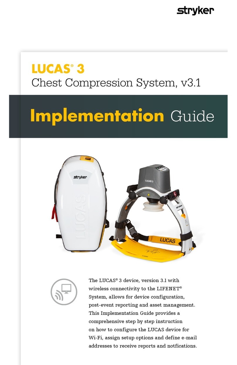
Stryker LUCAS 3 v3.1 User manual

Stryker

Stryker LUCAS 3 v3.1 User manual

Stryker 1509 User manual

Stryker

Stryker 1509 User manual

Stryker IsoAir 2941 User manual

Stryker

Stryker IsoAir 2941 User manual

Stryker InterPulse 0210 000 Series User manual

Stryker

Stryker InterPulse 0210 000 Series User manual

Stryker cub User manual

Stryker

Stryker cub User manual

Stryker GOLD Manual

Stryker

Stryker GOLD Manual

Stryker 738 User manual

Stryker

Stryker 738 User manual

Stryker Isolibrium 2971 User manual

Stryker

Stryker Isolibrium 2971 User manual

Stryker F-ABSLT2BER User manual

Stryker

Stryker F-ABSLT2BER User manual

Popular Medical Equipment manuals by other brands

TensCare Flexistim IF Instructions for use

TensCare

TensCare Flexistim IF Instructions for use

Liko Golvo 7000 ES Classic Instruction guide

Liko

Liko Golvo 7000 ES Classic Instruction guide

Getinge Maquet PowerLED II Instructions for use

Getinge

Getinge Maquet PowerLED II Instructions for use

KCI infoV.A.C Owner's service manual

KCI

KCI infoV.A.C Owner's service manual

Seating Matters Milano instruction manual

Seating Matters

Seating Matters Milano instruction manual

HEINE mini 3000 Instructions for use

HEINE

HEINE mini 3000 Instructions for use

AccuMed ANC-201 instruction manual

AccuMed

AccuMed ANC-201 instruction manual

Gima 28194 manual

Gima

Gima 28194 manual

Arjo Malibu Quick reference guide

Arjo

Arjo Malibu Quick reference guide

Kangaroo Joey Quick reference guide

Kangaroo

Kangaroo Joey Quick reference guide

Getinge Servo-u Cleaning Training

Getinge

Getinge Servo-u Cleaning Training

Innova 3100j owner's manual

Innova

Innova 3100j owner's manual

MacroMedics Thermoplastic Masks Instructions for use

MacroMedics

MacroMedics Thermoplastic Masks Instructions for use

Albrecht CDS WRIST BRACE DUO User instructions

Albrecht

Albrecht CDS WRIST BRACE DUO User instructions

Civco Ultra-Pro II reference guide

Civco

Civco Ultra-Pro II reference guide

Owandy Radiology i-max touch Service manual

Owandy Radiology

Owandy Radiology i-max touch Service manual

Gima 34301 manual

Gima

Gima 34301 manual

DJO Aircast AIRSELECT STANDARD Patient guide

DJO

DJO Aircast AIRSELECT STANDARD Patient guide

manuals.online logo
manuals.online logoBrands
  • About & Mission
  • Contact us
  • Privacy Policy
  • Terms and Conditions

Copyright 2025 Manuals.Online. All Rights Reserved.