Stryker Bari10 User manual

Bari10
Patient Helper
Installation Guide
2008/11 Patient Helper Installation Guide www.stryker.com
For Parts or Technical Assistance:
USA: 1-800-327-0770 (option 2)

2 Patient Helper Installation Guide www.stryker.com
Table of Contents
Introduction...............................................................................4
Intended Use ..........................................................................4
Patient Helper Features ..................................................................4
Patient Helper Illustration .................................................................4
Specifications .........................................................................5
Warning / Caution / Note Definition ..........................................................5
Symbols .................................................................................5
Setup Procedures ..........................................................................6
Operation Guide ...........................................................................8
Positioning the Carriage ..................................................................8
Positioning The Handle...................................................................8
Optional Patient Helper Assembly, Standard Components .............................................9
Optional Patient Helper Handle Assembly - 2230-100-037.........................................10
Optional Patient Helper Sliding Handle Assembly - 2230-100-038 ...................................10
Optional Patient Helper Carriage Assembly - 2230-100-039 .......................................10
Optional Patient Helper Stretcher Bolt Assembly - 2230-100-040....................................11
Patient Helper Frame Pin Assembly - 2230-100-041 .............................................11
Optional Patient Helper Lower Stretcher Assembly - 2230-100-042 ..................................11
Patient Helper Upper Stretcher Assembly - 2230-100-043.........................................11
Optional Patient Helper Frame End Cap Assembly - 2230-100-044 ..................................12
Optional Patient Helper Angle Cap Assembly - 2230-100-045 ......................................12
Optional Patient Helper Slider Cap Assembly - 2230-100-046 ......................................12

www.stryker.comPatient Helper Installation Guide 3
INTENDED USE
The Patient Helper is intended to be used in conjunction with the Bari10A Bariatric bed frame. It is intended to provide
support, increase stability while the patient is repositioning himself/herself.
CAUTION
Note: The Patient Helper is not intended to support the entire patients weight.
PATIENT HELPER FEATURES
Safe working load of 400 lbs.•
Designed to work in conjunction with the Bari10A fully-articulated mattress support platform. Also features an angled•
frame to avoid wall damage in the trendelenburg position.
Patient helper handle can be positioned left and right as well as forward and back for enhanced patient comfort.•
Easy rear mounting using existing bed frame mounting locations.•
Integrated bed frame mounts.•
Introduction
Return To Table of Contents
PATIENT HELPER ILLUSTRATION

4 Patient Helper Installation Guide www.stryker.com
Introduction
Return To Table of Contents
SPECIFICATIONS
Patient Helper
Safe Working Load 400 pounds 181 kg
Dimensions
(installed on
Bed frame)
Depth 44-3/4” 113,5 cm
Width 40” 101,6 cm
Height 63 -1/4” 160,7 cm
Patient Handle Slider 29” 73,7 cm
Carriage Assembly 15-1/4” 38,7 cm
Product Weight 200 lbs 91 kg
Stryker reserves the right to change specifications without notice.
Specifications listed are approximate and may vary slightly from unit to unit or by power supply fluctuations.
WARNING / CAUTION / NOTE DEFINITION
The words WARNING, CAUTION, and NOTE carry special meanings and should be carefully reviewed.
WARNING
Alerts the reader about a situation, which if not avoided, could result in death or serious injury. It may also describe
potential serous adverse reactions and safety hazards.
CAUTION
Alerts the reader of a potentially hazardous situation, which if not avoided, may result in minor or moderate injury to the
user or patient or damage to the equipment or other property. This includes special care necessary for the safe and
effective use of the device and the care necessary to avoid damage to a device that may occur as a result of use or
misuse.
Note
This provides special information to make maintenance easier or important instructions clearer.
Symbols
Warning / Caution - Consult accompanying documentation
Safe Working Load

www.stryker.comPatient Helper Installation Guide 5
Return To Table of Contents
Setup Procedures
Lower the bed to its lowest position or to a comfortable working height.
CAUTION
Use caution when maneuvering the components into position described in the following installation steps. Be aware of
your surroundings and any potential obstacles.
Place the left patient helper frame on the left side of the rear bed frame.1.
Drop (1) frame pin in place securing the left patient helper frame to the bed frame (see Figure 2). Secure frame2.
pin with hair pin.
Install lower stretcher beam to the left patient helper frame, loosely bolt with 3/8” bolt and nylon locking nut (see3.
Figure 3).
Place the right patient helper frame on the right side4.
of the rear bed frame.
Drop (1) frame pin in place securing the trapeze arm5.
to the bed frame (see Figure 4). Secure frame pin
with hair pin.
Figure 2 Figure 3
Figure 4

6 Patient Helper Installation Guide www.stryker.com
Return To Table of Contents
Setup Procedures
Loosely bolt lower stretcher beam with 3/8” bolt and nylon locking nut.6.
Install upper stretcher beam to the patient helper frame, loosely bolt with 3/8” bolts (2) and nylon locking nuts (2)7.
(see Figure 5).
Fit carriage assembly over the patient helper frames.8.
Install carriage bottom plates (2) to the carriage with (2) fasteners per side (see Figure 6). Utilize the center holes9.
on each side.
Install carriage bottom caps (4) to the carriage assembly with (4) fasteners per side (see Figure 8).10.
Slide carriage assembly as far forward as possible to middle of bed. Tighten lower stretcher nuts from steps 3-611.
(see Figure 5 and 6).
Slide carriage assembly as far rearward as possible to the head end of bed. Tighten the upper stretcher nuts from12.
step 7 (see Figure 7).
Check that carriage assembly moves freely back and forth when carriage adjustment handle is squeezed13.
(enabled).
Recalibrate the scale to ensure proper reading of patient weight.14.
Figure 5 Figure 6
Figure 7

www.stryker.comPatient Helper Installation Guide 7
Return To Table of Contents
Operation Guide
POSITIONING THE CARRIAGE
Refer to Figure 8.
Squeeze the carriage adjustment handle.1.
Slide the carriage to the desired position and release the carriage adjustment handle.2.
To ensure that the locator pins are securely seated in the frame it may be necessary to slide the carriage back and3.
forth slightly.
POSITIONING THE HANDLE
Refer to Figure 8.
Lift the handle slider with the attached chain up (lifting the handle slider locator pins from the carriage).1.
Move the handle slider to the desired position and lower it.2.
To ensure that the handle slider index pins are securely seated in the frame, it may be necessary to move the handle3.
slider back and forth slightly.
Figure 8

www.stryker.comPatient Helper Installation Guide 9
Return To Table of Contents
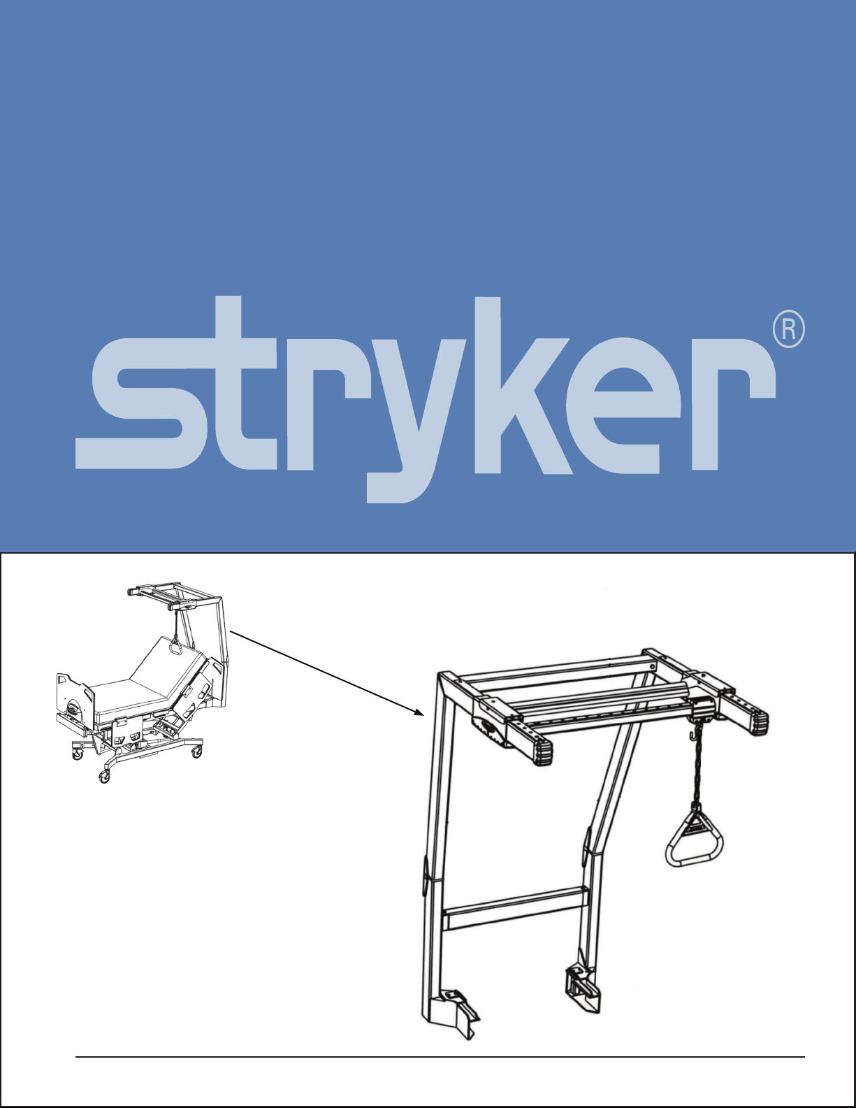
OPTIONAL PATIENT HELPER SLIDING HANDLE ASSEMBLY - 2230-100-038
Item Part No. Part Name Qty.
1 2230-100-180 Handle Slide Strip 4
2 2230-100-181 Handle Extr Rear Machined 1
3 2230-100-182 U-Clevis 1
4 2230-100-184 S-Hook 1
5 2230-100-185 Handle Extr. Front Machined 1
6 2230-100-186 Clevis Bolt 1/4-20 X 1-3/4 Grade 5 1
7 2230-100-179 1/4-20 Locknut 1
8 2230-100-187 310-32 x 3/4” 6-Lobe Pan Head
Mach Screw 4
OPTIONAL PATIENT HELPER CARRIAGE ASSEMBLY - 2230-100-039
Item Part No. Part Name Qty.
1 2230-100-188 Cross Bar Welded Assembly 1
2 2230-100-189 Slider Top Strip 2
3 2230-100-190 Rocker Welded Assembly 1
4 2230-100-191 Rocker Spring 2
5 2230-100-192 Slider Slide Strip 4
6 2230-100-193 Rocker Pivot Pin 2
7 2230-100-194 Rocker Pivot Pin Retainer 2
8 2230-100-195 Bottom Plate 2
9 2230-100-196 Slider Bottom Cap 4
10 2230-100-197 Bottom Cap Fastener, #10-32 x 5/8”
6-Lobe Pan Head Screw 12
OPTIONAL PATIENT HELPER HANDLE ASSEMBLY - 2230-100-037
Item Part No. Part Name Qty.
1 2230-100-174 Welded Chain, 800-lb Cap 1
2 2230-100-175 Trapeze Handle Gusset 1
3 2230-100-176 Handle 1
4 2230-100-177 Boot 1
5 2230-100-178 Trapeze Insert Bolt,
1/4-20 X 1, Grade 5 1
6 2230-100-179 1/4-20 Lock Nut 1
Optional Patient Helper Assembly, Standard Components

10 Patient Helper Installation Guide www.stryker.com
Return To Table of Contents
OPTIONAL PATIENT HELPER STRETCHER BOLT ASSEMBLY - 2230-100-040
Item Part No. Part Name Qty.
1 2230-100-198 Rear Stretcher Bolt,
3/8-16 X 3 1/2” Grade 5 2
2 2230-100-199 Nylon Insert Locknut, 3/8-16 UNC 2
PATIENT HELPER FRAME PIN ASSEMBLY - 2230-100-041
Item Part No. Part Name Qty.
1 2230-100-200 Pin Weldment 1
2 2230-100-201 Pin Weldment Fastener, Hairpin Clip 1
OPTIONAL PATIENT HELPER LOWER STRETCHER ASSEMBLY - 2230-100-042
Item Part No. Part Name Qty.
1 2230-100-202 Lower Stretcher 1
2 2230-100-198 Rear Stretcher Bolt,
3/8-16 X 3 1/2” Grade 5 2
3 2230-100-199 Nylon Insert Locknut, 3/8-16 UNC 2
PATIENT HELPER UPPER STRETCHER ASSEMBLY - 2230-100-043
Item Part No. Part Name Qty.
1 2230-100-203 Rear Stretcher 1
2 2230-100-198 Rear Stretcher Bolt,
3/8-16 X 3 1/2” Grade 5 2
3 2230-100-199 Nylon Insert Locknut, 3/8-16 UNC 2
Optional Patient Helper Assembly, Standard Components

www.stryker.comPatient Helper Installation Guide 11
Return To Table of Contents
Optional Patient Helper Assembly, Standard Components
OPTIONAL PATIENT HELPER FRAME END CAP ASSEMBLY - 2230-100-044
Item Part No. Part Name Qty.
1 2230-100-204 Tube End Cap 1
2 2230-100-197 Bottom Cap Fastener, #10-32 x 5/8”
6-Lobe Pan Head Screw 2
OPTIONAL PATIENT HELPER ANGLE CAP ASSEMBLY - 2230-100-045
Item Part No. Part Name Qty.
1 2230-100-205 Frame Angle Cap 1
2 2230-100-197 Bottom Cap Fastener, #10-32 x 5/8”
6-Lobe Pan Head Screw 2
OPTIONAL PATIENT HELPER SLIDER CAP ASSEMBLY - 2230-100-046
Item Part No. Part Name Qty.
1 2230-100-196 Slider Bottom Cap 1
2 2230-100-197 Bottom Cap Fastener, #10-32 x 5/8”
6-Lobe Pan Head Screw 2

CANADA
Stryker Canada
45 Innovation Drive
Hamilton, Ontario Canada
L9H 7L8
European Representative
Stryker France
ZAC Satolas Green Pusignan
Av. De Satolas Green
69881 MEYZIEU Cedex
France
EC REP
2006/XX XXXX-XXX-XXX REV X www.stryker.com
UNITED STATES
Stryker Medical
3800 E. Centre Ave.,
Portage, Michigan USA
49002
UNITED STATES
Stryker Medical
3800 E. Centre Ave.,
Portage, Michigan USA
49002
2008/11 Patient Helper Installation Guide www.stryker.com
Manufactured by Joerns Healthcare
Table of contents
Other Stryker Mobility Aid manuals