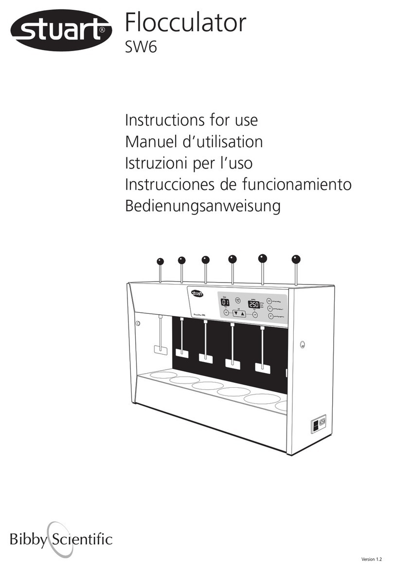
Stuart RE300 User manual

Assembly and operating instructions
Instructions de montage et d’utilisation
Istruzioni per il montaggio e per l’uso
Instrucciones de ensamblaje y funcionamiento
Montage- und Bedienungsanleitung
Rotary Evaporators
RE300 RE301 RE302
RE300P RE301P RE302P

2
Before use
If the equipment is not used in the manner described in this
manual the protection provided by the equipment may be
impaired.
Bibby Scientific rotary evaporators are designed to operate under the
following conditions:
❖ For indoor use only
❖ Use in a well ventilated area
❖ Ambient temperature range +5°C to +40°C
❖ Altitude up to 2000m
❖ Relative humidity not exceeding 80%
❖ Mains supply voltage fluctuations not
greater than ±10% of nominal
❖ Over voltage category 2 IEC 60364-4-443
❖ Pollution degree 2 IEC664
Rotary Evaporators
RE300 RE301 RE302
RE300P RE301P RE302P
Figure 1 Assembly
3
7
1
9
4
5
Twist grip height adjustment handle
Vacuum and water connections
6
On/Off switch
Rotating speed control
Glass angle control
Additional height
adjustment knob
2
Location & Services
In order to get the optimum performance from your Bibby Scientific
rotary evaporator careful consideration should be given to the
intended location. Please study the following notes before
commencing assembly.
Choose a convenient location, which will allow easy access to both
rotating and receiving flask.
In order to allow the glassware to be raised and lowered, a
minimum headroom of 850mm is required.
The location should have access to the following services:
Cold water supply capable of delivering 60l/hr is required for RE300,
RE300P, RE301, RE301P.
Electricity supply
Drain
Vacuum line (optional)
Assembly and operating instructions

3
Electrical Supply
THIS EQUIPMENT MUST BE EARTHED
Before connection please read and understand this instruction
manual and ensure that the line supply corresponds to that
shown on the rating plate. Bibby Scientific rotary evaporators
require a supply rated at 220-240V, 50/60Hz, single phase,~.
The power consumption of the rotary evaporator is 50W.
F3.15AL (20x5mm) fuses fitted in both live and neutral lines.
IF IN DOUBT CONSULT A QUALIFIED ELECTRICIAN
The unit is supplied with two mains leads fitted with IEC plugs for
connection to the instrument. One has a U.K. 3 pin plug and the
other has a 2-pin “Shuko” plug for connection to the mains.
Choose the lead appropriate for your electrical installation and
discard the other.
Should neither lead be suitable, take the lead with the U.K. plug and
replace the plug with a suitable alternative. This involves cutting off
the moulded plug, preparing the cable and connecting to the
rewireable plug in accordance with its instructions.
IT IS IMPORTANT THAT THIS OPERATION SHOULD ONLY BE
UNDERTAKEN BY A QUALIFIED ELECTRICIAN
The wires in the mains cable are coloured as follows:
BROWN - LIVE
BLUE - NEUTRAL
GREEN/YELLOW - EARTH
The unit is fitted with an IEC socket at the rear of the instrument for
connection of the mains lead. The appropriate mains lead should be
connected BEFORE connection to the mains supply.
Should the mains lead need replacement a cable of 1mm2of
harmonised code H05W-F connected to an IEC 320 plug should be
used.
N.B. The UK mains lead is protected by a 10A fuse mounted in the
plug top.
Safety Advice before Use
1. If the jacking mechanism is to be raised without the
glassware fitted great care must be taken. Without the
weight of the glass the jack will rise rapidly and can cause
damage to the mechanism. Unlock the jack carefully while
applying downward pressure to control the movement.
2. As the apparatus is likely to be used under vacuum, before
operation, examine all glassware carefully for scratches or
chemical etching. Use of damaged glassware under
vacuum could result in an implosion. In any case it is
recommended that the apparatus be operated behind a
safety screen.
3. Do not use the equipment in a hazardous atmosphere or
for mixing of hazardous materials.
4. Special care should be taken when using the equipment
with flammable solvents. The unit is not spark or explosion
proof.
5. In case of mains interruption, a fault or mechanical failure,
the unit will continue to operate on removal of the fault.
6. Beware of safety issues associated with rotating glassware
and when jacking glassware up and down.
Assembly
If the jacking mechanism is to be raised without the glassware
fitted great care must be taken. Without the weight of the
glass the jack will rise rapidly and can cause damage to the
mechanism. Unlock the jack carefully while applying
downward pressure to control the movement.
1. Unpack the rotary evaporator and identify the following
components:
Item Component Catalogue
No Number
1 Condenser RE100/CO or RE200/VC or
RE200/CF and RE200/CFD
2 Conical joint clip KCM29
3 Feed/vacuum release adapter RE100/VR
4 Florentine flask 1L FD1L/4RE
5 Receiving flask 1L RE100/RF/1L
6 Rotary evaporator motor stand RE300/MS
7 Spherical joint clip JC35
8 Vapour tube RE100/VT or RE100/VT/CF
9 Grey retaining cap
10 Circular metal spring
11 Vacuum seal
12 Sub-seal
13 Retaining clip
- UK lead
- European lead
- Spare fuse
12
11
Bearing house
Figure 2
Figure 3
Plastic screw bush
10
1
9
13
8
Spring
All components are
included in the rotary
evaporator motor stand
box

4
RE302, RE302P First remove the plastic connector at the back
of the condenser and fit into the hose. Secure with a suitable
clip, e.g. Jubilee. The connector and hose may now be fitted to
the vacuum line.
Note: A plastic cover is provided to reduce evaporation of cooling
agent.
Your rotary evaporator is now ready to be used.
Operation
Batch Operation
a) Remove the rotating flask (4) from the vapour tube (8) and fill
with the liquid to be evaporated. Ensure that the flask is never
more than half full. Secure the flask onto the conical joint using
the clip (2)
b) Examine the feed/release adapter (3) and ensure that both the
stopcock and vacuum release screwcap are closed (see fig. 4).
c) Ensure that water is flowing through the condenser at approx.
60l/hr (RE300 and RE301) or that the cold trap is filled with ice
or dry ice (RE302).
d) Ensure the speed control is set to 0.
e) Switch on the electricity supply.
f) Raise the glassware assembly to its highest position by turning
the handle anticlockwise. Note that the mechanism is spring
loaded. Once at the right height, turn the handle clockwise to
secure the position.
Note: Further height adjustment can be made by unscrewing the
additional height adjustment knob at the back of the stand (see
fig 1).
g) Place a suitable water bath directly under the rotating flask.
N.B. A water bath designed for use with the RE300 is
available from Bibby Scientific, code RE300B. Please
contact the sales office for details.
h) Lower the glassware until the rotating flask is partially immersed
in the water.
N.B. Ensure that the glassware does not touch the bath
and that no water overflows as the flask is immersed.
i) Switch the on/off switch to the on position. The green switch will
illuminate.
j) Set the speed control to the desired speed ensuring that rotation
is not so fast that water is splashed out of the bath.
2. Place the stand on a level surface. You will require easy access to
a water supply, drain, electric power and vacuum line to use your
rotary evaporator.
3. Pass the plain end of the vapour tube (8) through the right side
of the motor assembly and push into position until it locates
firmly behind the spring clip. The conical joint should be to the
right of the motor when viewed from the front.
4. Place the main vacuum seal (11) and sub-seal (12) onto the plain
end of the vapour tube (left) and slide them down until they
locate in the bearing housing. It is important that these
elements are fitted in the correct order and that the spring
loaded side of the main seal faces the bearing housing (see
fig.2).
5. Place the retaining clip (13) on the jointed side of the vapour
tube (right) and slide until it clips in the plastic screw bush (fig 2).
6. Place the grey retaining cap (9) over the butt joint of the
condenser (1) with the screwthread facing outwards and retain in
position with the circular spring (10) (see figure 3).
7. Place the condenser over the vapour tube so that it butts up to
the vacuum seal. Ensure the spherical joint faces downwards.
Secure by screwing the retaining cap onto the bearing housing.
If using a RE300 diagonal coil condenser, check that the vapour
tube is central and will not foul the condenser cooling coil.
8. The condenser may now be set to the required angle:
RE300 and RE300P Diagonal position
RE301, RE301P and RE302, RE302P Vertical position
9. Support the condenser while loosening the glass angle control.
10. Position condenser and tighten the control.
11. Hold the receiving flask (5) in position and secure with the
spherical joint clip (7).
12. Place the rotating flask (4) onto the end of the vapour tube and
secure using the conical joint clip (2).
13. Remove the grey plastic screwcap from the narrow end of the
condenser and assemble it to the feed/vacuum release adapter (3)
(see fig. 4).
14. Pass the PTFE tube through the condenser and vapour tube so
that the end is inside the rotating flask. Note that for the RE301
and RE302, the PTFE tube may have to be reduced in length to
fit into the Florentine flask (see fig. 4).
15. Secure by tightening the screw cap.
16. RE302 and RE302P only: Assemble the drain stopcock
(RE200/CFD) to the condenser using the grey plastic cap located
on the lower side arm.
17. To connect the condenser to the water supply, drain and vacuum
line, flexible hose of 9mm I.D. is required. Ensure you identify
every connection correctly before starting. Note tubing suitable
for use under vacuum must be used for the vacuum connection.
RE300, RE300P First remove the plastic connectors from the
condenser and fit into the hose. Secure with a suitable clip, e.g.
Jubilee. The connectors and hose may now be fitted to the inlet
and outlet water connections on the condenser (bottom two
connections linked to the coil). Proceed in the same way for the
vacuum connection (top connection).
RE301, RE301P First remove the plastic connectors from the
condenser and fit into the hose. Secure with a suitable clip, e.g.
Jubilee. The connectors and hose may now be fitted to the inlet
and outlet water connections on the condenser (bottom two
connections linked to the coil). Proceed in the same way for the
vacuum connection (top connection).
Continuous feed
stopcock
Continuous feed
inlet
Vacuum release
screwcap
Figure 4

5
k) If evaporation at reduced pressure is required a vacuum line
should be attached to the vacuum side arm on the condenser.
Turn on the vacuum and set to required value.
N.B. A vacuum pump designed for use with the RE300 is
available from Bibby Scientific, code RE2022C. Please
contact the sales office for details.
l) Set the temperature of the water bath as required.
m) When evaporation is complete release the vacuum by slowly
unscrewing the vacuum release screwcap. Set the rotation speed
to 0 and raise the glassware clear of the bath.
Continuous Feed Operation
When the apparatus is used under reduced pressure it is possible to
replenish the liquid in the rotating flask without interrupting the
evaporation or removing the flask.
The following procedure should be adopted.
a) Attach a length of flexible tubing to the continuous feed inlet of
the feed/release adapter (see fig.4).
b) Carry out instructions b-k for batch operation.
c) Immerse the free end of the flexible tubing into the container
holding the liquid to be evaporated. Ensure there is no strain on
the feed/release adapter.
d) With the apparatus under vacuum slowly open the stopcock on
the feed/release adapter. The vacuum will draw liquid into the
rotating flask.
e) Close the stopcock when sufficient liquid has entered the flask
Further quantities of liquid may be added during evaporation by
reopening the stopcock.
N.B. Ensure there is sufficient capacity in the flask to cope
with the addition. Never fill the flask more than half full.
N.B. Ensure there is sufficient capacity in the receiving flask
to cope with the condensation.
N.B. This evaporator should not be used with rotating
flasks bigger than 2 litres or receiving flasks bigger than 1
litre capacity.
f) If the receiving flask should require emptying during operation
the following procedure should be adopted:
iRelease the vacuum and stop rotation
ii Raise the glassware clear of the water bath
iii Wait until boiling stops and liquid stops dripping into the
receiving flask
iv The receiving flask may now be removed.
g) When evaporation is complete release the vacuum by slowly
unscrewing the vacuum release screwcap. Set the rotation speed
to 0 and raise the glassware clear of the bath.
Care and Maintenance
IMPORTANT: Before commencing any maintenance operation or
replacement of components parts the unit should be isolated
from the electricity supply, water supply and vacuum line.
These operations should only be undertaken by suitably
qualified personnel.
Note: F3.15AL (20x 5mm) fuses fitted in both live and neutral
lines.
Glassware
All glassware parts should be cleaned regularly and examined for
scratches, cracks and chemical etching. Replace any damaged parts.
Plastic coated glassware
The plastic coated glassware should not be exposed to temperature
above 80°C and is not dishwasher proof.
Cleaning
The main stand and motor should be cleaned using a mild detergent
solution.
Vacuum Seal
It is recommended that the vacuum seal be regularly washed with
distilled or deionised water and allowed to dry naturally.
Removal of the Vacuum Seal
a) Remove the rotating and receiving flasks
b) Remove feed/release adapter
c) Remove condenser
d) Withdraw vapour tube from the bearing housing by completely
unscrewing the plastic screw bush on the right side of the bearing
house.
e) The vacuum seal may now be removed.
f) Reassemble following the assembly instructions in this manual.
Servicing
It is recommended that any servicing or repair is only undertaken by
suitably qualified personnel.
Only spare parts supplied by Bibby Scientific or its agent should be
used. Fitting of non-approved parts may affect the performance of the
safety features of the instrument.
If in doubt, contact the Technical Service Department of
Bibby Scientific Ltd.
Stone, Staffordshire ST15 0SA
United Kingdom
Tel: +44 (0)8449 360234
Fax: +44 (0)8449 360235
e-mail [email protected]
www.bibby-scientific.com
This manual suits for next models
5
Table of contents
Languages:
Other Stuart Laboratory Equipment manuals
Popular Laboratory Equipment manuals by other brands

Belden
Belden HIRSCHMANN RPI-P1-4PoE installation manual

Koehler
Koehler K1223 Series Operation and instruction manual

Globe Scientific
Globe Scientific GCM-12 quick start guide

Getinge
Getinge 86 SERIES Technical manual

CORNING
CORNING Everon 6000 user manual

Biocomp
Biocomp GRADIENT MASTER 108 operating manual
