Stuart SBH CONC/1 User manual

Sample Concentrator
SBH CONC/1
Instructions for use

Thank you for purchasing this piece of Barloworld Scientific equipment. To get the best performance from the
equipment, and for your own safety, please read these instructions carefully before use.
This equipment is designed to operate under the following conditions:-
For indoor use only
Use in a well ventilated area
Ambient temperature range +5°C to +40°C
Altitude to 2000m
Relative humidity not exceeding 80%
Pollution degree 2 IEC664
If the equipment is not used in the manner described in this manual the protection provided by the equipment may
be impaired.
General Description
The Stuart sample concentrator, when used in conjunction with a Stuart block heater accelerates the evaporation
process of samples of solution for analysis. With the heat generated from the block heater and the steady flow of
gas above the surface of the sample, to carry away evaporated products, the rate of sample concentration is
significantly increased. The Stuart sample concentrator is only compatible with the three block, SBH130D/3 or
SBH200D/3, models of Stuart block heater.
The sample concentrator is made up of gas chamber sited on a height adjustable stand, to allow accurate
positioning above the samples. Hyperdermic needles penetrate a membrane within the gas chamber and carry the
gas from the chamber into the sample test tubes.
Safety Advice Before Use
Care should be taken when using hot apparatus, high temperatures can cause serious burns and ignite
combustible material
Never move or carry the unit when in use
Always use a gas regulator to control the flow of gas to the sample concentrator, do not exceed 2 psi at the
intake valve
Do not put hot objects near combustible objects
Do not place liquid directly into your block heater
Installation
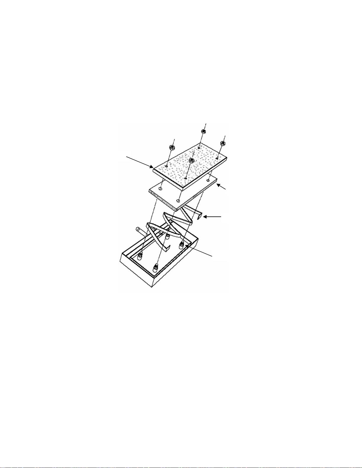
To help reduce packaging material the sample concentrator is delivered in three parts; the base board, the column
and carriage, and the gas chamber. Follow the instructions and diagram below to reassemble:
1. Unscrew the fastening knob at the rear of the base board, locate the column on the two pins in the
support bracket. Tighten the fastening knob to secure the column in place.
2. Insert the locating pin at the rear of the gas chamber into gas chamber location hole on the carriage,
taking care to line up the positioning pin, tighten the locking nut at the side of the carriage to secure the
gas chambers position.

Setup for Operation
Connect the intake nozzle at the rear of the gas chamber to a suitable supply of gas. The gas should flow through
a pressure reducing valve prior to connection to the gas chamber. Gas pressure should not exceed 2 psi at the
inlet valve of the gas chamber. Position your Stuart block heater on the base board, locating the two pins on the
bottom of the block heater onto the two location spigots on the base board. It is important that the block heater is
properly located to prevent misalignment of the needles later. The aluminium blocks should the centrally located
within the block heater, use the spacers provided.
Loosen the locking knob of the carriage and remove the gas chamber, lay the chamber upside down on a level
work surface. The needle matrix in the gas chamber has been designed to accommodate needles in various
patterns to suit the different sample configurations of the aluminium blocks. Each configuration has been labelled A
through F, please consult the guide below to know which configuration is appropriate for your aluminium blocks. As
an example, if you are using three SHT1/16 blocks for twelve 16mm tubes, you would need to insert needles in all
holes labelled C and all holes labelled D.
Tube Size and Number Insert Block code Hole label
0.5ml (6mm) x 30 SHT1/30 A
1.5ml (10mm) x 20 SHT1/22 B
2ml (12mm) x 20 SHT1/20 B
13mm x 20 SHT1/13 B
16mm x 12 SHT1/16 C & D
19mm x 8 SHT1/19 D,E & F
25mm x 6 SHT1/25 D & E
25mm x 6 SHT1/25 D & E
28mm x 6 SHT1/28 D & E
Column
Carria
g
e
Base board
Gas chambe
r
Base board
fastening knob
Locatin
g
p
in
Lockin
g
nut
Location s
p
i
g
ots
Positionin
g
p
in
Needles
Gas inlet

To insert the needles, press each needle firmly, pointed end first, through the relevant guide hole with enough
pressure to pierce the sealing membrane behind. The gas chamber membrane is self sealing so needles can be
removed and replaced several times. Only use needles where samples will be placed or gas will be wasted.
Replace the gas chamber onto the carriage and tighten via the locking nut.
Operation SBH CONC/1
Use the carriage handle to raise the needles to the highest point away from the block heater, insert your sample
test tubes into the block heater. Carefully lower the needles into your sample tubes, using the carriage handle.
Position the needles at the required height above the liquid surface, take care not to lower the needles into your
samples. Set the block heater to the desired temperature and switch on the gas supply, taking care not to exceed
2 psi. To further speed up evaporation, the height of the needles can be gradually lowered as the sample volume
reduces. On completion switch off the gas flow and raise the chamber out of the way. Take care the needles may
be hot at this point. Operation of your Stuart block heater will be detailed in the manual supplied with it, if further
copies are required these can be downloaded at www.barloworld-scientific.com.
Maintenance & Servicing
Periodically clean the instrument using a damp cloth and mild detergent solution. Do not use harsh or abrasive
cleaning agents.
Carriage Friction
The carriage works by means of a friction drive. To allow for wear the friction pressure can be increase by
tightening the four screws at the back of the carriage. All four screws must be tightened equally. The membrane
within the gas chamber is self healing, but after continued use you may start to notice that it isn’t performing as
efficiently as it was. Spare pads are available and can be fitted by following the instructions below:
Remove the gas chamber from the carriage, disconnect the gas pipe and place the chamber upside down on a flat
surface. Remove the four nuts from the corners of the matrix plate, lift off the matrix plate leaving the four spacers
in position. Lift off the sealing pad, ensuring that the support strip and spacers remain in position. Replace the pad
with the new one and follow the reverse procedure to reassemble the gas chamber.
Matrix
Sealing
Support
Spacer

The following spares and accessories are available from your laboratory dealer.
Description Catalogue Number
F7209 Needles, 76mm (pack of 100)
F7210 Needles, 127mm (pack of 100)
FSC4NCS Needles, 76mm PTFE coated (pack of 100)
FSC4NCL Needles, 127mm PTFE coated (pack of 100)
6101609 Base board
6101608 Spigot
6101604 Sealing pad
6101606 Spacer
6101605 Support strip
For a comprehensive list of parts required by service engineers conducting internal repairs and a service manual,
please contact the Technical Service Department of Barloworld Scientific Ltd. quoting both the model and serial
number. Only spare parts supplied or specified by Barloworld Scientific Ltd. or its agents should be used. Fitting of
non-approved parts may affect the performance and safety features designed into the instrument. If in any doubt,
please contact the Technical Service Department of Barloworld Scientific Ltd. or the point of sale.
Barloworld Scientific Ltd.
Stone, Staffordshire ST15 0SA
United Kingdom
Tel: +44 (0) 1785 812121
Fax: +44 (0) 1785 813748
e-mail equipment@barloworld-scientific.com
www.barloworld-scientific.com
Warranty
Barloworld Scientific Ltd warrants this instrument to be free from defects in material and workmanship, when used under
normal laboratory conditions, for a period of three (3) years. In the event of a justified claim Barloworld Scientific will replace
any defective component or replace the unit free of charge. This warranty does NOT apply if damage is caused by fire,
accident, misuse, neglect, incorrect adjustment or repair, damage caused by incorrect installation, adaptation, modification,
fitting of non approved parts or repair by unauthorised personnel.

Thank you for reading this data sheet.
For pricing or for further information, please contact us at our UK Office, using the details
below.
UK Office
Keison Products,
P.O. Box 2124, Chelmsford, Essex, CM1 3UP, Engl nd.
Tel: +44 (0)330 088 0560
F x: +44 (0)1245 808399
Em il: s [email protected]
Please note - Product designs and specifications are sub ect to change without notice. The user is responsible for determining the
suitability of this product.
Table of contents
Other Stuart Laboratory Equipment manuals

Stuart
Stuart SRT6 User manual

Stuart
Stuart Microcentrifuge 8500 User manual

Stuart
Stuart SMP10 User manual

Stuart
Stuart RE300 User manual

Stuart
Stuart SRT6 User manual

Stuart
Stuart SMP20 User manual

Stuart
Stuart SWB6D User manual

Stuart
Stuart SC6/100V/50 User manual

Stuart
Stuart SSM1 User manual

Stuart
Stuart SSL5 User manual


Popular Laboratory Equipment manuals by other brands

Distek
Distek 3100 Series Quick start instructions

Hach
Hach ORBISPHERE K1200 Basic user manual

enviromental express
enviromental express AutoBlock Fill Operation & instruction manual

Memmert
Memmert SV1524 operating manual

Northern Digital
Northern Digital Optotrak Certus user guide

Cascade Sciences
Cascade Sciences CVO-5-EX Series Installation & operation manual


