Issue 2, November 2017 Model 44D User Guide
Page 12 Studio Technologies, Inc.
details.) Commonly-used sources could
include analog I/O ports on broadcast
matrix intercom systems, audio consoles,
video storage and playback systems,
wireless microphone receivers, and audio
testing equipment. The circuitry associat-
ed with the line inputs is analog, electroni-
cally balanced, capacitor coupled, with an
impedance of 20 k ohms.
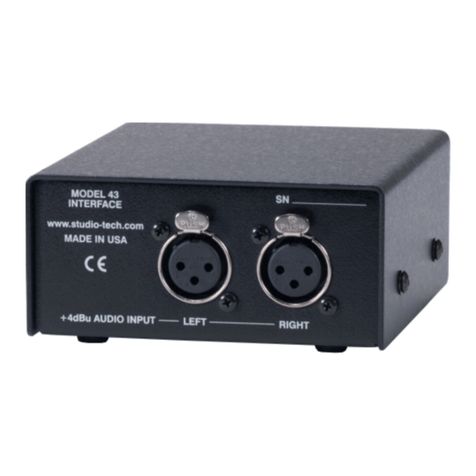
Two 3-pin female XLR connectors, located
on the Model 44D’s back panel, are used
for interfacing with the source signals.
Prepare 3-pin male XLR mating connec-
tors such that pin 2 is signal high (+),
pin 3 is signal low (–), and pin 1 is com-
mon/shield. It’s also highly possible that
an unbalanced source will interface cor-
rectly. With an unbalanced source begin
by connecting signal high (+) to pin 2 and
signal low/shield (–) to both pins 1 and 3.
If this results in hum or noise, next try con-
necting signal high (+) to pin 2 and signal
low/shield (–) only to pin 3; leave pin 1
unconnected (“floating”).
If the Model 44D has been configured to
operate in the tone generator mode the
two analog line inputs will not be active.
As such, no connections should be made
to either line input channel 1 or line input
channel 2.
Line Outputs
The Model 44D provides two line outputs.
These analog outputs are designed for
general-purpose use which could include
connecting to analog inputs on devices
including matrix intercom systems, trans-
mitters associated with wireless in-ear
monitors, audio consoles, or amplified
speakers. The circuitry associated with the
line outputs is analog, capacitor-coupled,
and has a source impedance of 200
ohms. It will perform optimally when driv-
ing loads of 2 k (2000) ohms or greater.
The nominal level of the line outputs is
configurable to be either +4 dBu or 0 dBu,
corresponding to SMPTE or EBU applica-
tions. (Refer to the Configuration section
of this guide for details.)
Two 3-pin male XLR connectors, located
on the Model 44D’s back panel, are
provided for interfacing the line outputs
with associated equipment. Prepare
3-pin female XLR mating connectors
such that pin 3 is signal high (+), pin 2
is signal low (–), and pin 1 is common/
shield. To connect to an unbalanced load
use pin 2 as signal high (+) and pin 1 as
low/shield; do not connect anything to
pin 3. Do not short pins 3 to pin 1 on the
Model 44D’s line output connectors as it
will stress the output circuitry.
General Purpose Inputs (GPI)
The Model 44D provides two general-
purpose input functions that are referred
to as GPI 1 and GPI 2. These functions
allow transport of the status of relay con-
tacts or open-collector logic signals. The
Model 44D’s GPI inputs use logic circuitry,
“pulled up” to 3.3 volts DC by way of resis-
tors, which are active whenever they are
brought to their logic low state. While the
GPI input circuitry is protected from over-
current and static discharge (ESD), care
should be taken to minimize the chance
that “nasty” signals can reach them.
The GPI inputs are active only when held
in their low state; they can’t be configured
to change state (“latch”) in response to
a logic pulse or momentary closure. Pins
on a 9-pin female D-subminiature con-
nector (DE-9F) are used for interfacing
with the GPI inputs and system common


