Model 545DR User Guide Issue 1, May 2022
Studio Technologies, Inc. Page 19
Model 545DR
INTERCOM INTERFACE
240 mA. That’s not always the easiest gure to calcu-
late but a web search will generally nd specications
for all commonly used devices. For example, a search
nds that the original (very, very early) version of the
BP-325 consumes a maximum of 85 mA of current.
According to this gure, one or two of these units can
be connected to a Model 545DR. All newer versions of
the BP-325 use surface-mount component technology
and have a maximum current draw of 65 mA. Up to
three of these “modern” BP-325 units can easily be
supported.
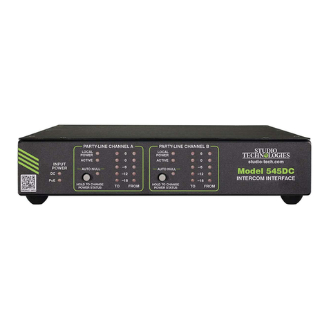
When local power has been enabled, the ACTIVE
status LED will light green when a minimal amount
of current is flowing from the Model 545DR to the
connected user device or devices. This will also cause
the virtual LED named PL Active in the STcontroller
application to light green. This current, 5 mA nominal,
provides a party-line power source-active signal to
the Model 545DR’s rmware, indicating that normal
operation is taking place. The rmware, in turn, will
cause the ACTIVE status LED to light, the STcontroller
application to light its virtual LED, and the two Dante
transmitter (output) audio channels to be in their
active (unmuted) state. (By muting the Dante trans-
mitter (output) channels when the intercom circuit is
not active, unwanted audio signals will be prevented
from passing to the outside world when no party-line
devices are connected.)
Note that a setting in the STcontroller application can
disable the requirement that a current draw of 5 mA
(nominal) or greater on pin 2 of the party-line XLR
connectors is required for the ACTIVE status LED
to light, the virtual LED in the STcontroller applica-
tion to light green, and the two transmitter (output)
audio paths to be active. This function is called
PL Active Detection and disabling it can be appro-
priate for special applications. Refer to the Model
545DR Conguration section for details regarding this
function and how it may be utilized.
The Model 545DR’s party-line intercom power supply
circuit operates under rmware control. This allows
detection of fault conditions and protection of the unit’s
circuitry. Upon initially enabling the Model 545DR’s
party-line intercom power supply no monitoring of
the intercom power output takes place for three sec-
onds. This allows the Model 545DR’s intercom power
supply circuitry and the connected intercom user
device or devices to stabilize. The LOCAL POWER
status LED will be lit solid and the virtual pushbutton
switch in the STcontroller application will show the
text On. The ACTIVE status LED, which responds to
the status of the DC voltage on pin 2 of the party-line
interface’s 3-pin XLR connectors, will light to indicate
that the output is active. The PL Active virtual LED
in STcontroller will light green. After this initial de-
lay, monitoring becomes active. A fault condition is
detected if the voltage on pin 2 falls below 24 for a
continuous 1-second interval. The rmware responds
to this condition by momentarily turning o the DC
power source to pin 2. It will also, as a warning, ash
the ACTIVE status LED and ash the virtual LED in
STcontroller. After a 5-second “cool-down” interval the
DC output will return to the same condition as upon
initial power up; power is again applied to pin 2, the
ACTIVE status LED will light, the virtual PL Active
LED will light green, and monitoring won’t begin for
another three seconds. A full short-circuit condition
applied to the Model 545DR’s party-line circuit will
result in a continuous cycle of four seconds on (three
seconds for startup and one second for detection) and
then ve seconds o.
External Party-Line Circuit Operation
When the LOCAL POWER status LED on the front
panel is not lit, and the virtual pushbutton switch in
STcontroller is labeled Off, the Model 545DR’s
party-line interface does not provide DC power on
pin 2 of the XLRs nor provides 200 ohms terminating
impedances on pins 2 and 3. In this mode, the Model
545DR is intended to be connected to an externally
powered party-line circuit. This party-line circuit must
provide the DC power and termination impedances
required to create the party-line intercom circuit. In this
mode, the Model 545DR simply serves in the same
fashion as that of another connected user device. (In
eect, the Model 545DR would have the technical
characteristics of a non-powered user device.) When
connected to a powered party-line circuit the Model
545DR’s ACTIVE status LED will light when approx-
imately 18 volts DC or greater is present on pin 2 of
the XLR connectors. In addition, the STcontroller’s PL
Active virtual LED will light green. When this condition
is detected, the Dante transmitter (output) channels
are placed in their active (non-muted) state. Other-
wise, they are o (muted) to maintain stable Model
545DR performance.


