Sturtevant Richmont 10467 User manual

Sturtevant Richmont
Global Reach. Local Support.
Sturtevant Richmont Div. of Ryeson Corp.
3203 N. Wolf Road Franklin Park, IL 60131
Phones: 847/455-8677 800/877-1347
Fax: 847/455-0347
E-Mail: [email protected]
Web Site: www.srtorque.com
Operating Instructions
Torque Control Verifier 2.4 GHZ
S/R Part No. 10467
Manual P/N: 857269 Rev. A
This product is not RoHS compliant.


Table of Contents
Contents Page
Chapter 1 - Introduction . . . . . . . . . . . . . . . . . . . . . . . . . . . . . . . . . . . . . . . . . . . . . . . . .1
Chapter 2 - Domestic Warnings (USA) . . . . . . . . . . . . . . . . . . . . . . . . . . . . . . . . . . . . . .4
Chapter 3 - TCV Installation . . . . . . . . . . . . . . . . . . . . . . . . . . . . . . . . . . . . . . . . . . . . . .5
Chapter 4 - Programming and FM Communications . . . . . . . . . . . . . . . . . . . . . . . . . . . . 9

Page 1
1 Introduction
The TCV/FM Switch Wrench System is designed to assist the manufacturer in closing
several gaps in the quality system that have hindered their quality improvement efforts.
The key capabilities this system enables are:
1. The ability to integrate manual torque wrenches into the automated line control system.
2. The ability to attain control of the actual torque wrench use process, not just the
wrench calibration process.
3. The ability to provide rapid and effective training in proper torque wrench use through
reinforcement of proper technique with every cycle of the wrench.
1.1 Control Concepts
The TCV works with the FM Switch Wrenches to bring systematized control to the use of
manual torque wrenches. The control is applied as follows:
1. There are three ways to use a clicker-type torque wrench. When used properly, a steadi-
ly increasing force is applied until the wrench clicks and the pressure is immediately
released and the tool resets. One improper use technique consists of applying force too
quickly (”jerking” the wrench). The other improper technique is to continue to apply force
after the click and overtorque the fastener.
2. When the correct technique is used the torque wrench spends a certain amount of time
in the “clicked” position. When the wrench is used too quickly it spends less time in the
clicked position. When it is rotated past the click it spends more time in the clicked posi-
tion.
3. The FM Switch Wrench is a preset clicker-type torque wrench. The torque is preset using
a torque tester to assure the wrench is accurately set. The torque setting is then locked
in.
4. The FM Switch Wrench has a timer that measures the duration of a click (cycle) of the
wrench. once the wrench has been accurately adjusted on the tester, variation in tech-
nique can be controlled by measuring and controlling the duration of the click.
5. An experiment is conducted to determine the correct use of the torque wrench (duration
of time in the clicked position) to obtain the correct torque on the joint. The accurately-
preset torque wrench is used to tighten the fastener(s) on the joint and an indicating
torque wrench is used to check the torque after the tightening. The experiment deter-
mines the minimum and maximum click duration to attain proper torque.
6. The minimum and maximum duration of a proper click is programmed into the TCV.
[Time Minimum or TMIN and Time Maximum of TMAX]
Page 2
7. In use, the FM Switch Wrench tightens a fastener. As soon as the wrench clicks a timer
on the wrench starts measuring time.
8. When pressure on the wrench is released and the wrench resets, the timer stops and the
duration of the click is transmitted to the TCV. The TCV compares the duration of the
click to the TMIN and TMAX specification limits.
9. The TCV immediately communicates to the operator the acceptability of that use of the
wrench. Light emitting diodes (LED’s) and a buzzer inform the operator whether or not
the wrench was used properly and the click accepted.
10. The TCV also uses the Input/Output Relays to communicate to programmable logic con-
trollers or other peripheral devices the acceptability, or lack of acceptability, of each use
of the wrench.
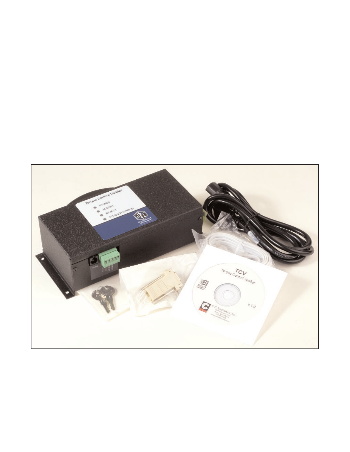
1.2 Component Nomenclature
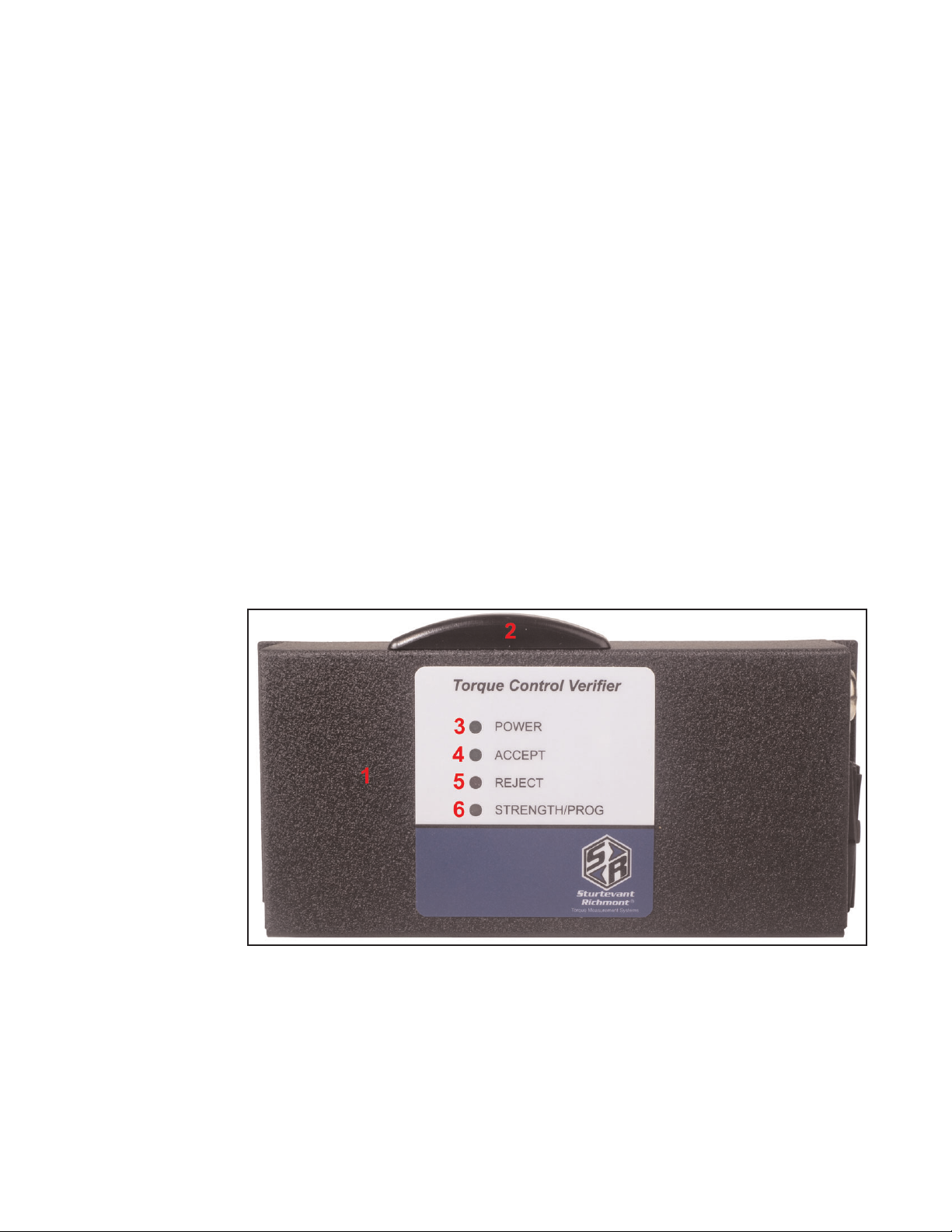
1Cabinet
The Cabinet houses all of the electronic components in the unit. On the left and right sides
of the Cabinet there are flanges with holes for mounting the unit to an appropriate support.
2Antenna Housing
The Antenna Housing protects the antenna for the 2.4Ghz band receiver.
3. Power Light
Emitting Diode
(LED)
The power LED
lights and
remains lit
when electric
power is sup-
plied to the unit
and the power
switch is in the
“On” position.
4Accept Light Emitting Diode (LED)
The Accept LED emits a green light to notify the operator when a wrench cycle meets the
duration specification.
5Reject Light Emitting Diode (LED)
The Reject LED emits a red light to notify the operator when a wrench cycle has been
rejected.
Page 3
6Strength/Prog Light Emitting Diode (LED)
In normal operation this Light Emitting Diode (LED) will emit green, yellow, or red light. If
the LED is green, the TCV is receiving a strong radio signal from the FM Switch Wrench
that it is working with. If it is yellow the signal strength is marginal. If this LED is red than
the signal strength is inadequate and the distance from the tool to the TCV should be
reduced. During programming this LED will be lit continuously to indicate the unit is in pro-
gramming mode.
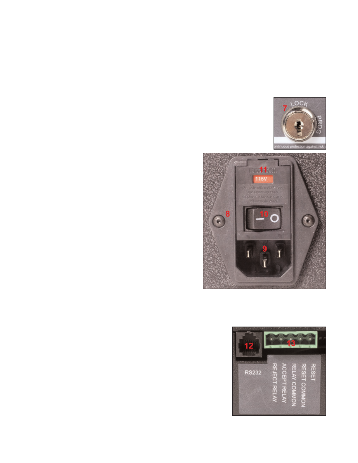
7Key Lock
The Key Lock permits and denies access to programming the unit.
When the Key lock is in the PROG position, programming functions are
enabled. When the Key Lock is in the LOCK position, the unit is in the
normal operating mode and only those functions are accessible.
8Power Entry Module
The Power Entry Module houses the Receptacle
for the Power Cord, the Voltage Selector and Fuse
Holder, and the Power Switch.
9Receptacle
The Receptacle accepts the female end of the
supplied Power Cord. The pronged end must be
plugged into a grounded outlet.
10 Power Switch
The Power Switch permits and denies electric
power to the TCV.
11 Voltage Selector/Fuse Holder
The Voltage Selector/Fuse Holder permits using
the TCV with either 115 VAC or 230 VAC electric
power sources. The correct power source must be selected during the installation process
and before electric power is supplied to the unit.
12 RS232 Communications Port
This port provides connection for the RS232 cable supplied
with the unit. The TCV is programmed with the supplied
software, and must be connected to the computer through
this port.
13 5-Pin Communication Receptacle
This receptacle mates with the supplied 5-pin connector,
and is used to communicate with programmable logic con-
trollers (PLC) and other devices.
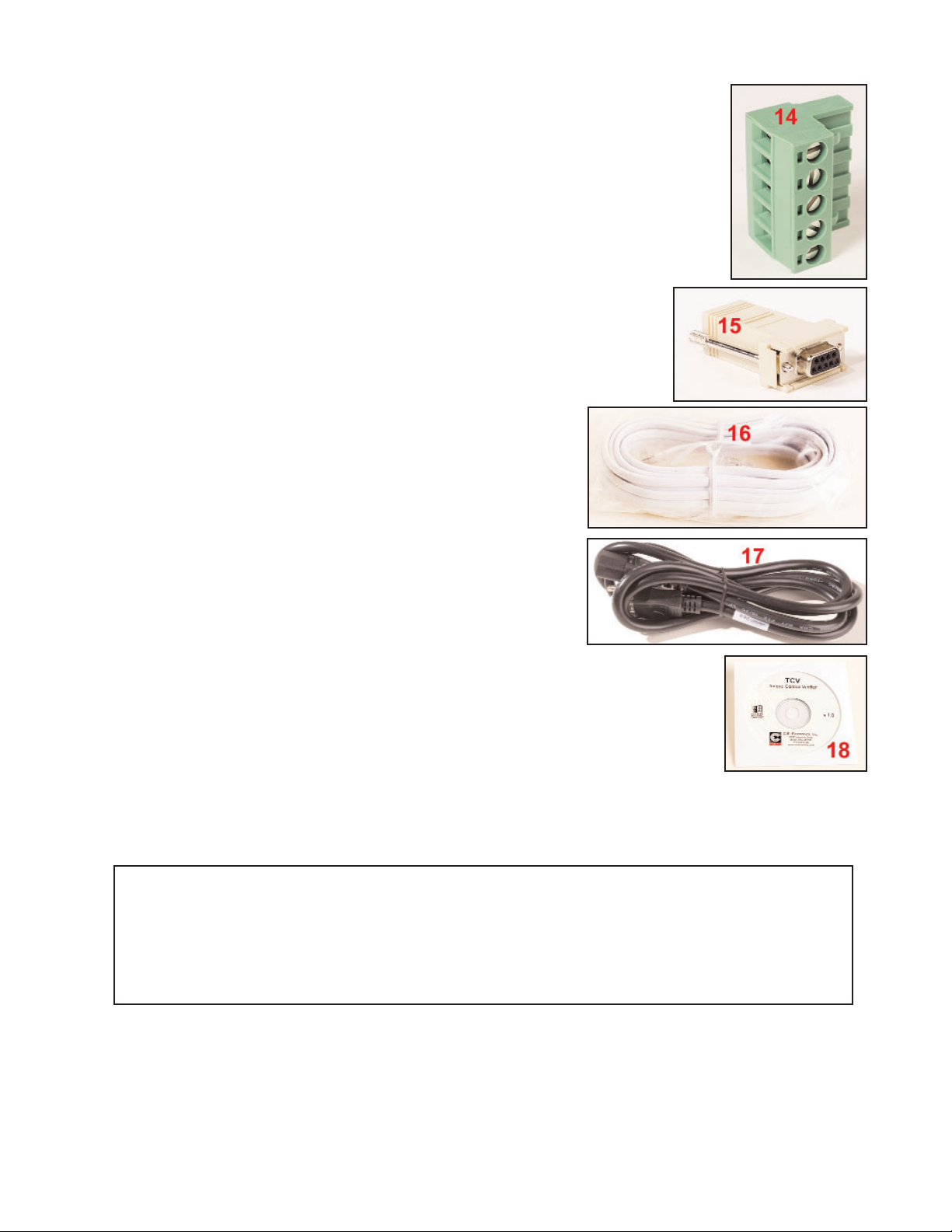
14 5-Pin Connector
Page 4
This male connector connects wires from PLC’s and other line control
devices to the pins on the mating receptacle on the TCV. The system is
designed to work with 24VDC I/O devices.
15 9-Pin Serial Convertor
This device attaches to the serial port on the computer that will run
the software used to program the TCV. It permits use of the sup-
plied serial cable to connect to the TCV when programming the
unit.
16 Serial Cable
This cable connects the RS232 port to the 9-Pin Serial
Convertor to the computer when programming the unit.
17 Power Cable
The Power Cable connects the TCV to the electric
power source. This is a standard pc-type cable, and any
cable of this type with a rated capacity of 120 VAC and
10 Amperes may be used.
18 TCV Software
The TCV software is supplied on the enclosed cd. It must be installed on
the computer that will be used to program the TCV before the TCV can
be programmed and used.
2 Domestic (USA) Warnings
INSTRUCTION TO THE USER
This equipment has been tested and found to comply with the limits for a class B digital
device, pursuant to part 15 of the FCC Rules. These limits are designed to provide reason-
Contains FCC ID: OUR-XBEE
The enclosed devise complies with Part 15 of the FCC Rules. Operation is subject to
the following two conditions: (1) this device may not cause harmful interference and (2)
this device must accept any interference received, including interference that may cause
delayed operation.

Page 5
able protection against harmful interference in a residential installation. This equipment gener-
ates, uses and can radiate radio frequency energy and if not installed and used in accor-
dance with the instructions, may cause harmful interference to radio communications.
However, there is no guarantee that interference will not occur in a particular installation. If
this equipment does cause harmful interference to radio or television reception, which can be
determined by turning the equipment off and on, the user is encouraged to try to correct the
interference by one or more of thefollowing measures:
* Reorient or relocate the receiving antenna.
* Increase the separation between the equipment and receiver.
* Connect the equipment into an outlet on a circuit different from that to which the receiver
is connected.
* Consult the dealer or an experienced radio/TV technician for help.
This equipment has been certified to comply with the limits for a class B computing
device, pursuant to FCC Rules. Operation with non-approved equipment is likely to result in
interference to radio and TV reception. The user is cautioned that changes and modifications
made to the equipment without the approval of manufacturer could void the user's authority to
operate this equipment.
3 Installation
There are two separate processes for installation; the TCV must be installed in the location
where it will be used and the software must be installed on the computer.
3.1 Installation Electric Safety
It is mandatory that the national, state, and local safety and wiring standards be
adhered to during installation. There standards take precedence over any information
presented in this section.
To avoid the hazard of electrical shock or burn, the following instructions must be
adhered to. Failure to follow these instructions may also cause damage to your unit and void
existing warranties.
• Do not energize (supply electric energy to) the unit until all connections have been
properly made.
• Equipment must be properly grounded before applying power. Units energized by cord
and plug must be connected to an approved and properly grounded receptacle.
• Ensure the power switch is in the “off” position before applying power.
Page 6
3.2 Mounting the TCV
This unit may be wall mounted, table mounted, beam mounted, suspended overhead,
pedestal mounted, or used without mounting. Mounting tabs are located on flanges on the
rear of the cabinet.
The mounting location should be in a stable, secure area so as to avoid damage to the unit
and avoid injury to the operator due to an inconvenient mounting. Locate the unit so that
ambient air can circulate freely around the cabinet.
This unit should be located to allow access to the front panel and connectors. The location
should allow for unrestricted and comfortable viewing of the front panel. The unit may be
remotely mounted, but should still be accessible.
3.3 Source Power
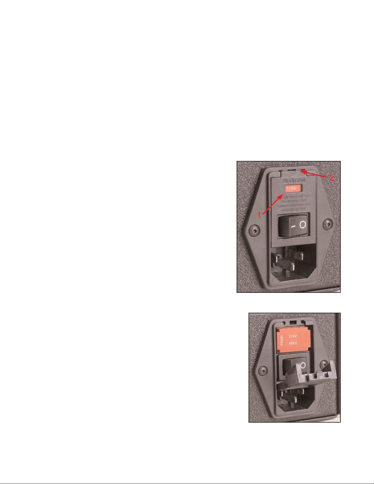
CAUTION! This unit is capable of being powered by 115 VAC
or 230 VAC (both 50 and 60Hz). Before powering up the
unit for the first time, make sure the voltage selection on
the power entry module matches the type of power being
applied.
1. The voltage setting for the unit is always displayed in a
window above the power switch, shown as #1 in the
image to the right. Always check the voltage for compati-
bility before supplying electric power to the unit. For this
example the voltage will be changed from 115VAC to
230VAC.
2. If the setting needs to be changed because it does not match
the power to be supplied, open the access door marked as #2
in the prior image by prying outward gently with a fingernail or
small screwdriver. Slide the red voltage selector/fuse holder
out of the module.

Page 7
3. Turn the red voltage selector/fuse holder over so the voltage
matching that of the power to be supplied has the top of the printed
voltage facing upwards.
4. Reinsert the red voltage selector/fuse holder into the module.
The face of the voltage selector/fuse holder will be slightly
recessed in the module when it has been properly reinserted.
5. Close the door over the voltage selector/fuse holder. The cor-
rect voltage, that which matches the voltage of the power to be
supplied to the unit, should now show through the window.
The TCV is fused at 1 Amp for 115VAC. The TCV is fused at
1 Amp for 230 VAC. The fuses are located on the sides of the
voltage selector/fuse holder, as shown in the accompanying
photograph.
6. Use the Power Cord to bring electric power from the source to the TCV. Check the Power
Switch and make certain that it is in the “Off” or de-energized position. Connect one end of
the cord to the TCV at the Power Entry Module and plug the other end into the electric
outlet.
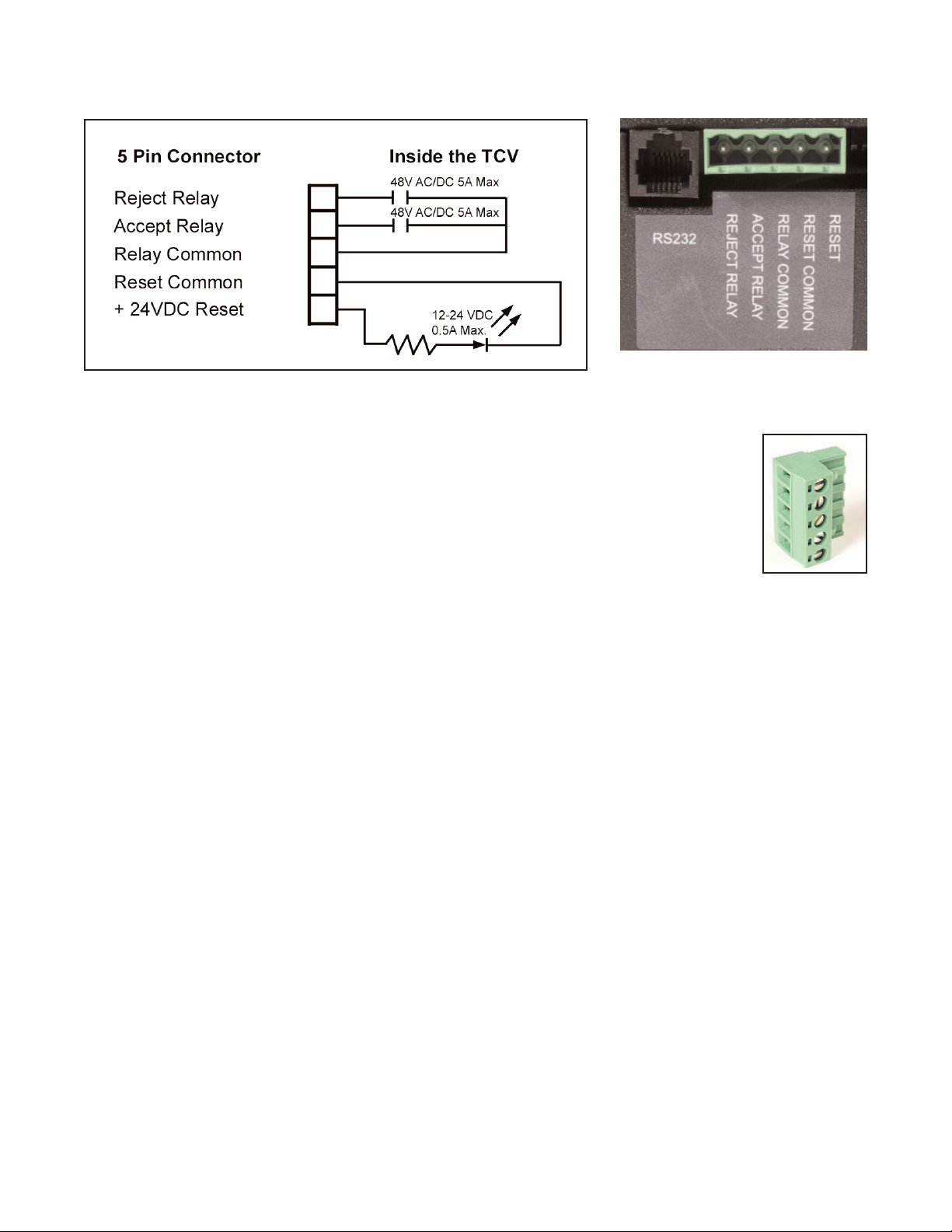
3.4 Connecting Peripheral Devices
The TCV has relay outputs and an optically isolated RESET input. All of the relays can be
accessed through the 5-Pin Connector on the bottom of the Cabinet. The TCV also has a
serial port labeled “RS232”. The serial port is used to connect to a personal computer or lap-
top computer running the TCV software to accomplish programming of TCV parameters.
Page 8
The circuit diagram below is that for the relays.
The TCV Input/Output control system is designed primarily for use with 24VDC systems.
Follow all national and state electrical codes and regulations when connecting
peripheral devices to the TCV. Do not exceed the voltages and amperages
shown above.
Connect the wires from the peripheral devices to the TCV via the external 5-Pin
Connector. This connector has screw clamps for the wire for each pin.
3.5 Software Installation and Computer Connection
A compact disk packaged with each TCV contains the software required to program the unit.
The software must be installed and used to program the TCV before the unit is placed in
service.
This software will work on machines using the Windows XP Professional operating system.
Close all programs not necessary to computer operation before executing the installation pro-
cedure below.
1. Insert the TCV program compact disk into the compact disk drive on the computer that will
be used to control the settings on the TCV.
2. Use “My Computer” or “Windows Explorer” to open the compact disk drive conating the
compact disk.
3. When the files on the compact disk are displayed, double-click the left mouse button on
the “Setup” file. This will start an automated program installation and setup routine.
4. Follow the instructions displayed on screen to install the program.
5. Remove the compact disk and store in a safe location.

Page 9
5 Programming the TCV with CLK_TUNE Software (V1.0)
The CLK-TUNE software for programming the TCV performs all the functions necessary to
set the parameters that determine whether an individual cycle (or click) of the wrench is
acceptable or not. The software also manages the serial communications with the TCV unit.
Before sending settings to the TCV it is necessary to connect the computer to the TCV using
the supplied 9-Pin to phone cable convertor and the phone cable supplied with the unit. We
recomment performing this function before starting the software.
Follow standard Windows procedures to open the CLK-TUNE software. The software will start
and a small title window will open on the computer screen for a few seconds. This window will
close automatically and the CLK-TUNE operating screen will be displayed.
Comm Port
The software communicates with the TCV via serial communications through a 9-pin serial
port on the computer. Many computers have more than one communications port. Use the
mouse to select the port to which you have connected the TCV. Position the cursor over
the correct communications port selection and click the left mouse button to make that the
active port for communicating with the TCV.
Min Pull Time (secs)
This is the miunimum amount of time that the wrench must be in the “clicked” position for an
acceptable cycle. It is designed to eliminate “jerking” or too rapidly cycling the wrench. To set
this time position the cursor in the rectangular value setting area and click the left mouse but-

Page 10
ton one time to make this the active selection. The border of the box will become thick, as
displayed in the image in this section. Type in the desired minimum duration of a wrench
cycle (seconds). When the first value (whole seconds) is typed in, the numbers will move to
the right side of the box and a small triangle will indicate the active number. The value must
be in an “N.NN” format. Once the number has been entered, use the Enter key to make the
value active and use the down arrow or mouse to go to the next parameter to be entered or
action to be taken. The minimum time must be a value less than the maximum time.
Max Pull Time (secs)
This is the miunimum amount of time that the wrench must be in the “clicked” position for an
acceptable cycle. It is designed to eliminate pulling the wrench past the “click”. To set this
value, use the arrow keys or mouse to make this the active selection. Type in the maximum
amount of time that the wrench is to be in the “clicked” position. The number must be in the
“N.NN” format. The number may be as high as 2.55 seconds and must be higher than the
minimum pull time. Once the number has been entered, use the Enter key to make the value
active and use the down arrow or mouse to go to the next parameter to be entered or action
to be taken.
Time Between Cycles (secs)
This is the minimum amount of time between wrench cycles (clicks). It is designed to help
prevent the error of tightening the same fastener twice while missing another fastener on a
multi-fastener assembly. The number must be in the “N.N” format.
Channel #
The TCV 2.4 GHz and SLTC-FM 2.4 GHz have seven available channels from which to
select. Use the pull-down menu to select the channel that you wish the TCV and SLTC-FM
Switch Wrench to use.
Beep on Accept
The TCV can be set to emit a beep when an acceptable wrench cycle is communicated to the
TCV. This audio operator communication can be set to be active (On) or inactive (Off). Use
the pull-down menu to make your selection.
Relay Mode
The relays in the TCV can be set to either Latching or Momentary. Use the pull-down menu to
make your selection.
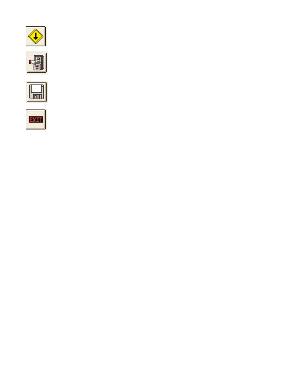
Upload Button
This button is used to obtain the current settings for the TCV from the unit when it is
connected and the power is on.
Stop Button
This button is used to stop an upload from or download to the TCV from the com-
puter running the software.
Page 11
Download Button
This button is used to download a set of parameters from the software to the TCV.
File Button
This button is used to store a parameter set for later use. The user can select the
name of the parameter set for later recall.
Get Parameter Set Button
This button is used to retrieve a previously-stored parameter set.
Exit Button
This button closes the window and exits the CLK_TUNE software.
If additional information is needed, please contact us using the information provided on the
front of the manual.
Table of contents
Other Sturtevant Richmont Controllers manuals


