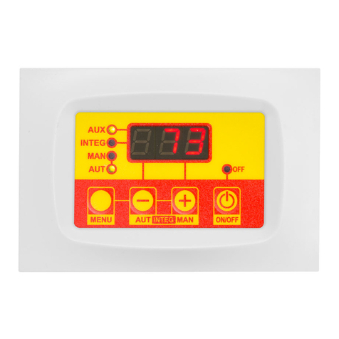
TiEmme MB250 User manual

Pag. 1 / 70 DMAN802000093-Manual MB250 Hydro Wood-Pellet STD11
Date: 09/11/2018
TECHNICAL MANUAL
MB250 HYDRO
WOOD-PELLET STD11

Pag. 2 / 70 DMAN802000093-Manual MB250 Hydro Wood-Pellet STD11
Revision Date
Description
09/11/2018
Condition to enter Modulation and Standby in hydraulic plant 11 have been modified
Cleaning Engine and Cleaning Engine 2 in Check up have been added
Night Modality has been added
Parameter A25 has been added
14/09/2018
Added Service, Cleaning, Working Hours, Ignition entries in Monitor Menu
24/07/2018
Introduction of V14 parameter
12/07/2018
Introduction of the Brazier Cleaning Engine in Check Up (P51 parameter)
Introduction of T25 timer. During this time exhaust fan2 works at power VS14 after
transition from Pellet to Wood in Combi 2 modality
Introduction of A49 parameter in order to remove Buffer Thermostat management
in Wood modality
Introduction of A51 enabling parameter for the management of Er02 error during
Wood modality
The management of Thermostat L01 validation while decreasing has been modified
during the Stabilization phase
Introduction of the Cleaning On message during periodic cleaning phase
Configuration 11 has been added
20/04/2018
Boiler probe thermostat maximum range increased, NTC 231K probe added
Automatic Extinguishing function modified
Door management modified

Pag. 3 / 70 DMAN802000093-Manual MB250 Hydro Wood-Pellet STD11
1INTRODUCTION ...................................................................................................................... 5
2LANGUAGE PACKAGES............................................................................................................. 5
3INSTALLATION ........................................................................................................................ 6
CONNECTIONS ............................................................................................................................. 6
FIRST CONFIGURATION .................................................................................................................. 9
DIGITAL INPUTS......................................................................................................................... 13
High Voltage1 (Safety Thermostat) .................................................................................... 13
High Voltage 2 (Pressure Switch) ....................................................................................... 13
Encoder Auger .................................................................................................................. 13
Encoder Combustion Fan ................................................................................................... 13
Grid Sensor....................................................................................................................... 13
Door Sensor...................................................................................................................... 13
Pellet Thermostat.............................................................................................................. 13
Flow Switch ...................................................................................................................... 14
Room Thermostat ............................................................................................................. 14
Pellet Level ....................................................................................................................... 14
Limit Switch Cleaning Engine ............................................................................................. 15
Limit Switch Cleaning Engine 2 .......................................................................................... 15
Limit Switch Brazier Cleaning Engine .................................................................................. 15
External Chrono ................................................................................................................ 15
ANALOG INPUTS ......................................................................................................................... 15
Exhaust Probe (Thermocouple) .......................................................................................... 15
Boiler Probe ...................................................................................................................... 15
Buffer Probe / Top Buffer Probe......................................................................................... 15
Bottom Buffer Probe.......................................................................................................... 15
Boiler Return Probe / Flow................................................................................................. 15
DHW Probe....................................................................................................................... 16
External Probe .................................................................................................................. 16
Water Pressure Sensor ...................................................................................................... 16
Photo Resistance............................................................................................................... 16
Primary Air Flow or Vacuum Sensor.................................................................................... 16
Room Probe...................................................................................................................... 17
4KEYBOARDS........................................................................................................................... 18
LCD100 .................................................................................................................................. 18
DISPLAY K100........................................................................................................................... 18
DISPLAY K400........................................................................................................................... 19
Home Page 1 .................................................................................................................... 19
Home Page 2 .................................................................................................................... 20
ERROR MESSAGES AND VIEWS ........................................................................................................ 20
5USER MENU ........................................................................................................................... 22
USER MENU 1............................................................................................................................ 22
USER MENU 2............................................................................................................................ 26
6FUNCTIONING STATES..........................................................................................................27
PELLET MODALITY ...................................................................................................................... 28
Off ................................................................................................................................... 28
Check Up.......................................................................................................................... 28
Ignition ............................................................................................................................ 28
Stabilization ...................................................................................................................... 30
Ignition Recovery.............................................................................................................. 30
Run Mode......................................................................................................................... 31
Modulation........................................................................................................................ 32
Standby............................................................................................................................ 33
Safety .............................................................................................................................. 35
Extinguishing .................................................................................................................... 35
Block................................................................................................................................ 36
WOOD MODALITY ....................................................................................................................... 36
Block and Off Wood .......................................................................................................... 36

Pag. 4 / 70 DMAN802000093-Manual MB250 Hydro Wood-Pellet STD11
Wood Run Mode ............................................................................................................... 36
Wood Modulation .............................................................................................................. 37
Wood Standby .................................................................................................................. 38
Wood Safety ..................................................................................................................... 38
Wood Extinguishing........................................................................................................... 38
COMBI MODALITY....................................................................................................................... 40
7OTHER FUNCTIONS ............................................................................................................... 42
INTERNAL CHRONO MANAGEMENT................................................................................................... 42
COMBUSTION STANDBY ................................................................................................................ 42
AUTOMATIC COMBUSTION POWER................................................................................................... 42
CHANGE POWER DELAY................................................................................................................ 42
SYSTEM MAINTENANCE 1FUNCTION................................................................................................ 42
SYSTEM MAINTENANCE 2FUNCTION................................................................................................ 43
FAST EXTINGUISHING .................................................................................................................. 43
EXTINGUISHING IN IGNITION PHASE................................................................................................ 43
AUTOMATIC SWITCH OFF FUNCTION................................................................................................ 43
SUPPLY VOLTAGE LACK MANAGEMENT.............................................................................................. 43
AUGER FEEDING IN WOOD MODALITY.............................................................................................. 43
PERIODICAL CLEANING OF BRAZIER................................................................................................. 44
CONFIGURABLE OUTPUTS MANAGEMENT ........................................................................................... 44
Safety Valve ..................................................................................................................... 44
Load Pellet Engine............................................................................................................. 44
Output under Thermostat .................................................................................................. 44
Cleaning Engine ................................................................................................................ 44
Combustion Fan 2 ............................................................................................................. 45
Heating Fan ...................................................................................................................... 45
Air Valve........................................................................................................................... 45
Error Signalling ................................................................................................................. 45
Cleaning Engine 2 ............................................................................................................. 45
Auger 2 in On-Off mode................................................................................................. 46
Auger 2 Always On ........................................................................................................ 46
Air Valve 3..................................................................................................................... 46
Air Valve 2..................................................................................................................... 46
Mixer Valve ................................................................................................................... 47
Pump P3 ....................................................................................................................... 48
Brazier Cleaning Engine.................................................................................................. 48
Auger block ................................................................................................................... 50
CLIMATIC FUNCTION ................................................................................................................... 50
PRIMARY AIR FLOW SENSOR ......................................................................................................... 50
HYDRO -AIR MODALITY............................................................................................................... 52
Air Exchanger Fan Management......................................................................................... 52
Plumbing Plant Management.............................................................................................. 52
Pump and Valve Anti-Lock Function............................................................................. 60
Sanitary Function ....................................................................................................... 60
Pressure Sensor Selection ........................................................................................... 60
8SYSTEM MENU PARAMETERS ................................................................................................ 61
AUGER MENU ............................................................................................................................ 61
COMBUSTION FAN MENU .............................................................................................................. 61
COMBUSTION FAN 2MENU ........................................................................................................... 62
HEATING FAN MENU.................................................................................................................... 62
THERMOSTATS MENU .................................................................................................................. 63
TIMERS MENU ........................................................................................................................... 64
ENABLE MENU ........................................................................................................................... 66
PRIMARY AIR FLOW SENSOR MENU ................................................................................................. 68
WATER PRESSURE SENSOR THRESHOLD MENU ................................................................................... 69
COUNTERS MENU ....................................................................................................................... 69
OUTPUT’S TEST MENU ................................................................................................................. 69
RESTORE PARAMETER’S FACTORY VALUE MENU .................................................................................. 70

Pag. 5 / 70 DMAN802000093-Manual MB250 Hydro Wood-Pellet STD11
1Introduction
The MB250 Controller is a device to manage stoves and boilers with automatic ignition and pellet loading.
The operation of the heating system is determined by reading the exhaust temperature, water temperature,
and through the acquisition of the parameters setup by the user. The parameters of the controller are fully
configurable inside the menu. By setting the parameters it is possible to:
modify the operation of the heating system according to the user’s specific requirements
modify the operation of the controller to a suit any stove or boiler
This manual illustrates in detail the controller installation steps, the configuration, the functioning and the
technical characteristics.
2Language Packages
Languages
K100, K400 and K700 have the following languages available:
Italian
Polish
Dutch
Latvian
Portuguese
Serbian
Danish
Estonian
German
Romanian
Swedish
Hungarian
French
Czech
Turkish
Lithuanian
Spanish
Russian
Greek
Slovak
English
Bulgarian
Croatian
Slovenian
LCD100 and LCD100 touch keyboards have the following languages available:
Set 1
Set 2
Set 3
English
English
English
Italian
Slovenian
Turkish
French
Serbian
Czech
German
Romanian
Polish
Spanish
Greek
Russian
Portuguese
Hungarian
Bulgarian
Firmware Codes
Control Board
MB250
FSYSD01000174
K Series Keyboard
K100
FSYSF04000027
K400
FSYSF13000005
K700
FSYSF18000005
LCD Series Keyboard
Set 1
Set 2
Set 3
LCD100
FSYSF01000292
FSYSF01000293
FSYSF01000294
LCD100 Touch
FSYSF03000084
FSYSF03000085
FSYSF03000086

Pag. 6 / 70 DMAN802000093-Manual MB250 Hydro Wood-Pellet STD11
3Installation
Connections
In the below picture is showed the connections of the main board and its outputs and inputs.
Follow the indications of the connection modalities for a correct installation.
For a correct and secure functioning connect always ground connection
For a correct operation follow carefully the modalities of connection indicated to
avoid damage to electronics
Make connection in a tidy way; keep separated cables of low voltage (probes,
contacts, control panel flat) and cables of high voltage (power source, loads) to
reduce interference problems

Pag. 7 / 70 DMAN802000093-Manual MB250 Hydro Wood-Pellet STD11

Pag. 8 / 70 DMAN802000093-Manual MB250 Hydro Wood-Pellet STD11
Pin
Function
Technical Specifications
1-2
Line
Version 230Vac 10% 50/60 Hz
Version 110Vac 10% 50/60 Hz
Fuse T 6,3 A
3-4
Combustion Fan
Triac, feeding output (Max 0.8 A)
5-6
Output V2 configurable
Configuration parameter: P44
Triac, feeding output (Max 0.8 A)
7-8
Pump
Relay, feeding output (Max 3 A)
9-10
Ignition Resistance
Relay, feeding output (Max 3 A)
11-12
High Voltage 1 Input
Short-circuit if not used
High voltage input, contact open/closed
13-14
High Voltage 2 Input
Short-circuit if not used
High voltage input, contact open/closed
15-16
Auger Motor
Triac, feeding output (Max 0.5 CV)
17
-
Neutral
18
-
Phase
19-20-21
Output Aux2 configurable
Configuration parameter: P48
Relay, free contact output (Max 3 A)
19: COM
20: N.C.
21: N.O.
22-23-24
Electrovalve
Relay, feeding output (Max 3 A)
22: N
23: FOFF
24: FON
25-26
Exhaust Probe
Thermocouple K
25: Red (+)
26: Green (-)
27-28
Input IN2 configurable
Configuration parameter: P74
Analog Input (NTC 10K probe)/Digital Input
29-30
Input IN3 configurable
Configuration parameter: P75
Analog Input (NTC 10K probe)/Digital Input
31-32
Boiler Probe
Analog Input NTC 10K if PA44=0
Analog Input NTC 231K if PA44=1
33-34-35
Input IN5 configurable
Configuration parameter: P76
Analog Input (NTC 10K probe)/Digital Input
36
Not used
-
37-38-39
Water Pressure Sensor
Analog Input
40-41-42
Encoder Sensor (see parameter A57)
40: +5V
41: GND
42: signal
43-44-45
Input IN8 configurable
Configuration parameter: P71
43: +12V
44: signal
45: GND
46-47
Output Aux3 configurable
Configuration parameter: P36
Relay, free contact output (Max 3 A)
47: N.O.
48: COM
48-49-53
Input IN9 configurable
Configuration parameter: P70
48: signal
49: GND
53: +12V
50-51-53
Input IN10 configurable
Configuration parameter: P73
50: signal
51: GND
53: +12V
51-52-54
Encoder Sensor (see parameter A57)
51: GND
52: signal
54: +5V
CN1
Local Keyboard Connection
-
RS232
Serial Port Connection
Serial Port RS232
RS485
Serial Port Connection
Serial Port RS485
Connect to the Earth
CONNECT ALWAYS
-

Pag. 9 / 70 DMAN802000093-Manual MB250 Hydro Wood-Pellet STD11
First Configuration
First of all, set parameter P42 to choose the Hydro or Air modality (see par. 7.15). If the Hydro modality is
set, select the plumbing plant (parameter P26 in the Default Settings Menu of the Technical Menu). Then
set the configurable outputs via parameters of the Default Settings Menu P44, P48and P36, then set the
parameters P70, P71,P73, P74, P75 and P76. Finally set the parameters P25 to choose the Combustion
Fan type (with or without encoder) and P81 to choose the Auger type (with or without encoder).
Set also the parameter PA44 to define the NTC probe to connect to input IN4.
Plumbing Plants (for more details see section 7.16.2):
Configuration 0 (P26=0)
FL P1 P2
S1
FL
P1 P2
S1
Configuration 1 (P26=1)
S1FL P1
P2
FL
P1
P2
S1
Configuration 2 (P26=2)
Configuration 3 (P26=3)
Configuration 4 (P26=4)
S2
P1 P2
S1
Configuration 5 (P26=5)
Configuration 6 (P26=6)
Configuration 7 (P26=7)
Configuration 8 (P26=8)
P1 P2-3
mix
S1
S3
A
B
C
S2
Configuration 9 (P26=9)
Configuration 10 (P26=10)
S3
S2
P1 P3
S1 P2
Configurazione 11 (P26=11)

Pag. 10 / 70 DMAN802000093-Manual MB250 Hydro Wood-Pellet STD11
Whenever you select plant 10, properly shorting Puffer Probe Inputs (Probe S2) and ACS Probe (Probe S3),
it is possible to select one of the following plant automatically:
Probe
Condition
Setted Plant
Probe
Condition
Setted Plant
Puffer
Short circuit
Plant 5
Puffer
Short circuit
Plant 2
DHW
Short circuit
DHW
Probe
P1
S1
P1 Pump: pins 7-8
To more details see the par. 7.16.27.16.2 -
Plumbing Plant Management, Configuration 5.
S3
P1
S1 P2
P1 Pump: pins 7-8, P2 Valve: Pins 22-24
To more details see the par. 7.16.2 - Plumbing Plant
Management, Configuration 2.
Probe
Condition
Setted Plant
Probe
Condition
Setted Plant
Puffer
Probe
Plant 4
Puffer
Probe
Plant 10
DHW
Short circuit
DHW
Probe
S2
P1 P3
S1
P1 Pump: pins 7-8, System Pump P3
To more details see the par. 7.16.2 - Plumbing Plant
Management, Configuration 4.
N.B. In paragraph 7.17 P3 Pump is identified as P2
Pump.
S3
S2
P1 P3
S1 P2
Recirculation Pump P1: pins 7-8, P2 Valve: pins 22-
24, System Pump P3
To more details see the par. 7.16.2 - Plumbing Plant
Management, Configuration 10.
When the system detects a different input configuration error message Er56. For the actual setting of the
system, if plant 10 is selected or the existing probes configuration is modified, follow this steps:
1. set the parameters: P26=10
P74 or P75 or P76=8
P74 or P75 or P76=9
P36 or P44 or P48=14
2. put the system in Off state
3. cut off the power
4. make the appropriate changes to the inputs Buffer probe and DHW probe
5. restore power
6. control in Views menu if the temperature detected by the present probes coincides with the setting
made
7. repeat all operation from step one if necessary
Configurable Output (for more details see section 7.13):
Connected Devices
Parameter
Value
Output
V2
(
P44
)
Aux2
(
P48
)
Aux3
(
P36
)
Output not used
0
√
√
√
Safety Valve (see 7.13.1)
1
√
√
√
Loading Engine (see 7.13.2)
2
√
√
√
Output under thermostat (see 7.13.3)
3
√
√
√
Cleaning Engine (see 7.13.4)
4
√
√
√
Combustion Fan 2 (see 7.13.5)
5
√
–
–
Heating Fan (see 7.13.6)
6
√
–
–
Air Valve (see 7.13.7)
7
√
√
√
Error Signalling (see 7.13.8)
11
√
√
√
Cleaning Engine 2 (see 7.13.9)
13
√
√
√
Pump P3
14
√
√
√
Auger 2 Pause-Work (see 7.13.10)
16
√
–
–
Auger 2 always On (see 7.13.11)
17
√
√
√

Pag. 11 / 70 DMAN802000093-Manual MB250 Hydro Wood-Pellet STD11
Air Valve 3 (see 7.13.12)
20
√
√
√
Air Valve 2 (see 7.13.14)
22
√
√
√
Mixer Valve (see 7.13.15)
23
–
–
√
Brazier Cleaning Engine (see7.13.16)
25
√
√
√
Auger Block (see 7.13.17)
26
–
√
√
Brazier Cleaning Engine (direction) (see 7.13.16)
33
–
√
–
The Aux2 output is a free contact output; in case it is necessary to use it to control a supplied load 230 Vac,
follow the diagram below. If the output is activated, there is 230 Vac between the connectors 19-21.
If the output is deactivated, there is 230 Vac between the connectors 19-20.
Even the Aux3 output is a free contact output; in case it is necessary to use it to control a supplied load 230
Vac, follow the diagram below.
IN8 Configurable Input (for more details see sections 3.3 and 3.4):
Connected Devices
Parameter Value
Input
IN8 (
P71
)
Input not used
0
√
Primary Air Flow Sensor
1
√
Pellet Level Sensor
2
√
Photo resistance
3
√
IN2, IN3, IN5, IN9 and IN10 Configurable Inputs (for more details see sections 3.3 and 3.4):
Connected Devices
Parameter
Value
Input
IN2
(
P74
)
IN3
(
P75
)
IN5
(
P76
)
IN9
(
P70
)
IN10
(
P73
)
Input not used
0
√
√
√
√
√
Grid Sensor
1
√
√
√
√
√
Door Sensor
2
√
√
√
√
√
Pellet Thermostat
3
√
√
√
√
√
Room Thermostat
4
√
√
√
√
√
Flowswitch
5
√
√
√
√
√
Pellet Level Sensor
6
√
√
√
√
√
External probe
7
√
–
–
–
–
Return Boiler/Flow/DHW probe
8
–
√
–
–
–
Buffer probe /High Buffer Probe
9
–
–
√
–
–
Limit Switch Cleaning Engine
10
√
√
√
√
√
Limit Switch Cleaning Engine 2
11
√
√
√
√
√
Limit Switch Brazier Cleaning Engine
12
√
√
√
√
√
Room Probe
15
√
√
√
–
–
External Chrono
17
√
√
√
√
√
Photo resistance
18
√
√
√
–
–
Bottom Buffer probe
23
√
√
√
–
–
NOTE
If a contact is connected on input IN10, it has to be connect to pins 50 and 53.
F
17
N
19
20
21
22
23
24
AUX 1
FOFF
AUX 2
COM
N.C.
N.O.
18
FON
N
46
47
AUX3
48
49
50
51
IN 9
IN 10-11
S10
GND
S9
54
53
52
COM
N.O.
GND
S11
+V
+CV
Uscita Aux3
Output Aux 2
Output Aux3

Pag. 12 / 70 DMAN802000093-Manual MB250 Hydro Wood-Pellet STD11
Keyboards links
The keyboards use the RS485 protocol for connection to the control board. This standard allows connections
to long distances, with high noise immunity, provided that they comply with the directives of the protocol.
It is therefore recommended to use shielded twisted pair wires for connection.
Remote Keyboard
The Remote Keyboard allows remote control of the system. It’s functionality is similar to the Local Keyboard;
on board is inserted a sensor for detecting the ambient temperature and the displayed temperature is
sensed by said sensor.
Links
Below is shown how connect the Remote Keyboard to the SYPlug02 board that leads out of the stove or
boiler the control board’s RS232 and RS485 connectors.

Pag. 13 / 70 DMAN802000093-Manual MB250 Hydro Wood-Pellet STD11
Digital Inputs
High Voltage1 (Safety Thermostat)
When the contact is opened in every functioning state, after a delay equal to timer T09, the system goes in
Extinguishing and then in Block; the display visualises error High Voltage 1 Safety (Er01).
This input is suitable to connect a Manually Rearmed Thermostat; if the system does not use this input
short-circuit Pins 11-12 of the connector.
High Voltage 2 (Pressure Switch)
When the contact is opened, after a delay equal to timer T10, the system goes in Extinguishing and then in
Block; the display visualises error High Voltage 2 Safety (Er02). This management can be disabled during
Wood Modality by setting A51=0.
The state of this input is not detected if the Combustion Fan is off.
This input is suitable to connect a Pressure Switch; if the system does not use this input short-circuit Pins
13-14 of the connector.
Encoder Auger
To the connections 40-41-42 you can connect an input to read the encoder signal in order to adjust rounds
number of auger. Connect as showed in the table.
Encoder Combustion Fan
To the connections 40-41-42 or 51-52-54 you can connect an input to read the encoder signal in order to
adjust rounds number of combustion fan. Connect as showed in the table.
Grid Sensor
If the contact is closed and the system is in Pellet modality, the display shows the message Er20; if the
system is in Off state, it isn’t possible the ignition until the contact is opened. If the system is in Combo
modality, at the time of switching to Pellet modality, if the contact is closed, the system goes in Off state
and Pellet modality. In Wood modality the sensor status doesn’t influence the system behavior.
If the input is set but not used, leave the pins unconnected.
Door Sensor
In case of opening the door, on the panel appears the message 'Port', the Augers turn off and the
functioning of the Combustion Fans depends from the parameter P96 value.
P96=0: both Fans are blocked if the exhaust temperature is higher than the thermostat Th01 in
Pellet modality or Th13 in Wood modality, in Block State or, if in a different state, independently
from Th01/Th13.
P96=1: Combustion Fan 1 goes to maximum speed and Combustion Fan 2 is blocked if the exhaust
temperature is higher than the thermostat Th01 in Pellet modality or Th13 in Wood modality, in
Block state or, if in a different State, independently from Th01/Th13.
P96=2: Combustion Fan 1 is blocked and Combustion Fan 2 goes to maximum speed if the exhaust
temperature is higher than the thermostat Th01 in Pellet modality or Th13 in Wood modality, in
Block state or, if in a different State, independently from Th01/Th13.
P96=3: both fans go to maximum speed if the exhaust temperature is higher than the thermostat
Th01 in Pellet modality or Th13 in Wood modality, in Block state or, if in a different State,
independently from Th01/Th13.
P96=4:both fans go to a speed set by parameters PA46 and PA47 if the exhaust temperature is
higher than the thermostat Th01 in Pellet modality or Th13 in Wood modality, in Block state or, if
in a different State, independently from Th01/Th13.
In case of use of the Photoresistance and while the system is in OFF, while the door is open the reading of
the light will be ignored.
If the door is open, the Timer T21 resets.
In case in which the sensor is selected but not used, short circuit the corresponding pins of the board.
Pellet Thermostat

Pag. 14 / 70 DMAN802000093-Manual MB250 Hydro Wood-Pellet STD11
When the contact switches on there is return of flame and until the contact is open, the display shows Er06
and:
if P44, P36 or P48 are equal to sixteen or seventeen (product with two Auger), the Auger is Off,
the Auger 2 and fan combustion are always On.
if P44, P36 and P48 are equal to one (product with Auger and Safety Valve), the Auger is Off, the
combustion fan is off and the Safety Valve closes.
if P44, P36 and P48 are different from one, sixteen and seventeen (product with one Auger), the
Combustion Fan is always On, the Auger is On if A44=0, is Off if A44=1.
If the contact is opened in Ignition, the output heating resistance is turned off.
If the input is set but not used short circuit the relative pins.
Flow Switch
To use a Flow Switch input set the parameter (P26=0, 1, 5, 6). Leave unconnected the pins if it is set but
not used.
Room Thermostat
Setting the parameter Enables A01 it is possible to:
if A01 = 0
contact closed
: the system goes in Ignition
contact open
: the system goes in Extinguishing
This functioning is available only in Pellet or Combo modality, and P11 = 4 (Combi 2)
if A01 = 1
contact closed
: the system goes in Run Mode
contact open
: the system goes in Modulation
if A01 = 2
contact closed
: the system goes in Run Mode
contact open
: the system goes in Standby
if A01= 3
contact closed
: the system reactivates the Pump
contact open
: if the temperature of the water exceeds the value of the Thermostat for the
Activation of the System Pump (Th19 or Th59), the system blocks the Pump until the
temperature reaches the Th21 or Th78 Thermostat
if A01= 4
contact closed
: the system reactivates the Pump and goes in Run Mode
contact open
: the system goes in Standby and blocks the Pump as in case 2 and 3
if A01= 5
contact closed
: the system goes in Run Mode
contact open
: the system goes in Standby with Pellet, and in Modulation with Wood.
if A01= 6
contact closed
: the system reactivates the Pump
contact open
: the system with Wood passes to Modulation, with Pellet if the temperature of the
water exceeds the value of the Thermostat for the Activation of the System Pump (Th19 or
Th59), the system blocks the Pump until the temperature reaches the Th21 or Th78
Thermostat
if A01= 7
contact closed
: the system reactivates the Pump and goes in Run Mode
contact open
: the system goes in Standby and blocks the Pump as in case 2 and 3 with Pellets,
goes to Modulation with Wood.
NOTE:
If there is a sanitary water demand in Wood Mode, the Room Thermostat does not block the Pump and, if it
was previously blocked by the Thermostat, it is reactivated. In plants 4 and 10 the Pump is blocked in Wood
mode too.
If A13=2, on Summer all operations of Room Thermostat are disabled except for A01=0.
If A01=1,2, 3, 4, 5, 6, 7 and the input is not used short circuit the relative pins.
Pellet Level
Setting the parameters P36, P44 and P48 in the Technical Menu it is possible to:
P44, P48 and P36 different from 2

Pag. 15 / 70 DMAN802000093-Manual MB250 Hydro Wood-Pellet STD11
If the level falls below the threshold, the system signals the lack of fuel for a time equal to the
T24, then it goes in Extinguishing with error (Er18). If the tank is filled the system stops every
signalling and it is possible to restart it.
This control is done only in Pellet modality.
P44=2 or P48=2 or P36=2
If the level falls below the predetermined threshold, the output that controls the Load Pellet
Connection:
Level
Pellet
Sensor
+Vc
Sx
GND
+V
-GND
Out
+V of sensor to the pin 43 or 53
-GND of sensor to the relative GND pin of the
input set as Pellet Level
Out of sensor to the relative pin Sx of the
input set as Pellet Level
If a Pellet Level Sensor is connected with output in DC and the voltage is greater than 5v, connect it to the
IN8 or IN9 input. These inputs can support voltage until 12V. Sensors with maximum output 5V, can be
connected to every input. The temperature controller can support only Pellet Level sensors PNP type.
Limit Switch Cleaning Engine
Use the contact only if an output is set as Cleaning Engine.
Limit Switch Cleaning Engine 2
Use the contact only if an output is set as Cleaning Engine 2.
Limit Switch Brazier Cleaning Engine
Use the contact only if an output is set as Brazier Cleaning Engine.
External Chrono
At the closure of contact, the system goes in Ignition, at the opening it goes in Extinguishing.
Analog Inputs
Exhaust Probe (Thermocouple)
To the connections 25-26 is available the Exhaust Probe. With this probe, it is possible to read the exhaust
temperature.
This probe is a Thermocouple K sensor. The sensor can read from 0 to 500°C with a precision of 1 °C. If you
don’t connect the probe to the system you’ll read 900 °C.
NOTE: even if the sensor can read temperatures in the range 0 ÷ 500 °C the entire sensor wiring can work
only in the range 0 ÷ 500 °C.
TiEmme elettronica is not responsible of any damage or bad functioning of the probe due to a wrong use of
it (i.e. thermic and mechanical stresses to the probe).
Boiler Probe
To the connections 31-32 is available the Boiler Probe. With this probe, it is possible to read the water
temperature of the boiler. If you don’t connect the probe to the system you’ll read -50 °C, in case of short-
circuit you’ll read the maximum value.
Buffer Probe / Top Buffer Probe
To use this input as a Probe set the parameter P26=4, 8, 10, 11 and P74, P75 or P76=9.
This probe is a NTC 10K sensor; it can read from -50 to 110°C with a precision of 1 °C. If you don’t connect
the probe to the system you’ll read -50 °C. In case of short-circuit you’ll read 110 °C.
Bottom Buffer Probe
To use this input as a Probe set the parameter P26=4, 8, 10, 11 and P74, P75 or P76=23.
If you don’t connect the probe to the system you’ll read -50 °C. In case of short-circuit you’ll read 110 °C.
Boiler Return Probe / Flow
To use this input as a Probe set the parameter P26=7, 8, 9 and P74, P75 or P76=8.
This probe is an NTC 10K sensor and its range is -50÷110 °C with a precision of 1 °C. If you don’t connect
the probe to the system you’ll read -50 °C, in case of short-circuit you’ll read 110°C.

Pag. 16 / 70 DMAN802000093-Manual MB250 Hydro Wood-Pellet STD11
DHW Probe
To use this input as a Probe set the parameter P74, P75 or P76=8 and P26=2, 3, 10, 11.
This probe is an NTC 10K sensor and its range is 0 ÷ 110° C with a precision of 1 °C.
If you don’t connect the probe to the system you’ll read -50 °C, in case of short-circuit you’ll read 110°C.
External Probe
To use this input as a Probe set the parameter P74, P75 or P76=7.
This probe is an NTC 10K sensor and its range is -50÷110 °C with a precision of 1 °C. If you don’t connect
the probe to the system you’ll read -50 °C, in case of short-circuit you’ll read 110°C.
Water Pressure Sensor
To the connections 37-38-39 is available the Pressure Sensor to read the boiler’s pressure. It can read from
0 to 3000 mbar. To activate the alarms due over/under pressure of the boiler, set the parameter A14=1. In
this case, set the minimum and maximum pressure levels (SP01 and SP08 parameters).
Photo Resistance
The probe detects the flame brightness of the brazier. The brightness range goes from 0 to 100. If not
connected the read value is 0. In case of use on input IN8 connect it to pin 44 (signal) and 33 (+5V).
The photo resistance is enabled only in Pellets modality. If the system provides a Wood
modality it is necessary to use also the thermocouple.
Primary Air Flow or Vacuum Sensor
Setting the parameter P71 it is possible to choice the sensor to connect to the Input IN8.
If P71=1 it is possible to connect an Air Primary sensor or a Vacuum sensor; the sensor works on the
combustion parameters (Auger and Combustion Fan). The range is 0÷2000.
In the case of disconnected probe the system will read a speed value of 0. In case of failure adjustment it
shows the message Er17, in case of broken sensor or not connected properly, will appear the message
Er39.
If an Air Primary sensor is used:
Connections:
43=+12V (red wire)
44=SEG (brown wire)
45=GND (black wire)
If a Vacuum sensor is used:
has to be placed horizontally through the bracket supplied
the connections for the pressure reading (see Figure 1 and 2) should be directed downward.
Connections:
43=+12V (red wire)
44=SEG (yellow wire)
45=GND (black wire)
Caption:
1 Connection pressure P1 (high pressure)
2 Connection pressure P2 (low pressure)
3. Electrical connections

Pag. 17 / 70 DMAN802000093-Manual MB250 Hydro Wood-Pellet STD11
Room Probe
To use this input as a Probe set the parameter P74, P75 or P76=15.
This probe is an NTC 10K sensor and its range is -50÷110 °C with a precision of 1 °C. If you don’t connect
the probe to the system you’ll read -50 °C, in case of short-circuit you’ll read 110°C.
Setting the parameter A01 it is possible to:
thermostat not reached
: the system goes in Ignition
thermostat reached
: the system goes in Extinguishing
This functioning is available only in Pellet or Combo modality, and P11 = 4 (Combi 2)
if A01 = 1
thermostat not reached
: the system goes in Run Mode
thermostat reached
: the system goes in Modulation
if A01 = 2
thermostat not reached
: the system goes in Run Mode
thermostat reached
: the system goes in Standby
if A01= 3
thermostat not reached
: the system reactivates the Pump
thermostat reached
: if the temperature of the water exceeds the value of the Thermostat for the
Activation of the System Pump (Th19 or Th59), the system blocks the Pump until the
temperature reaches the Th21 or Th78 Thermostat
if A01= 4
thermostat not reached
: the system reactivates the Pump and goes in Run Mode
thermostat reached
: the system goes in Standby and blocks the Pump as in case 2 and 3
if A01= 5
thermostat not reached
: the system goes in Run Mode
thermostat reached
: the system goes in Standby with Pellet, and in Modulation with Wood.
if A01= 6
thermostat not reached
: the system reactivates the Pump
thermostat reached
: the system in Wood modality passes to Modulation, in Pellet modality, if
the temperature of the water exceeds the value of the thermostat for the activation of the
System Pump (Th19 or Th59), the system blocks the Pump until the temperature reaches the
Th21 or Th78 Thermostat
if A01= 7
thermostat not reached
: the system reactivates the Pump and goes in Run Mode
thermostat reached
: the system goes in Standby and blocks the Pump as in case 2 and 3 with
Pellets, goes to Modulation with Wood.
NOTE:
If there is a sanitary water demand in Wood Mode, the Room Thermostat does not block the Pump and, if it
was previously blocked by the Thermostat, it is reactivated. In plants 4 and 10 the Pump is blocked in Wood
mode too.
If A13=2, on Summer all operations of Room Thermostat are disabled except for A01=0.
If A01=1,2, 3, 4, 5, 6, 7 and the input is not used short circuit the relative pins.

Pag. 18 / 70 DMAN802000093-Manual MB250 Hydro Wood-Pellet STD11
4Keyboards
The keyboards of the system can be local (mounted on the machine) or remote (mounted outside of the
machine), type of touch screen or LCD. The recognition by the baseboard of a keyboard, is via the
communication address of the same keyboard. Program: address 16 for local key, address 17 for remote key
LCD100
The main frame shows:
time and date, chrono activation,
combustion power, combustion recipe,
system operating state, error code, main
temperature, main thermostat,
summer/winter modality, combi
functioning
Button
Function
P1
Exit menu and submenu
P2
Ignition and extinguishing (push for 3 seconds), Reset errors (push for 3 seconds), Enable/disable
chrono
P3
Enter in User Menu 1/submenu, Enter in User Menu 2 (push for 3 seconds), Save data
P4
Enter in Visualizations Menu, Increase
P5
Enable chrono program, Change the operation mode of the system if P11=2, 3, 4 (only in Off
state)
P6
Enter in Visualizations Menu, Decrease
Led
Function
Led
Function
D1
Heating Resistance On
D7
Output Aux3 On
D2
Auger On
D8
-
D3
Pump On
D9
External Chrono reached
D4
Valve On
D10
Pellet Sensor signaling lack of material
D5
Output V2 On
D11
Room Thermostat reached
D6
Output Aux2 On
D12
DHW demand
Display K100
The main frame shows:
time and date, chrono
activation, combustion power,
heating power, system operating
state, error code, main
temperature, main thermostat
Button
Function
K1
Exit Menu/Submenu
K2
Ignition and extinguishing (push for 3 seconds), Reset errors (push for 3 seconds), Enable/disable
chrono
K3
Enter in User Menu 1/submenu, Enter in User Menu 2 (push for 3 seconds), Save data
K4
Enter in Visualizations Menu, Increase
K5
Enter in Visualizations Menu, Decrease
Led
Function
Led
Function
Room Thermostat reached
External Chrono reached
Winter
Summer
Pellet Modality/Wood Modality
Combi Modality On

Pag. 19 / 70 DMAN802000093-Manual MB250 Hydro Wood-Pellet STD11
Display K400
The K400 control panel allows to move between screens with the horizontal or vertical swipe. The symbols
near the following pictures point out the possibility to move with the swipe in that screen.
Home Page 1
The home page is
composed of two pages:
Date and time, main
temperature, main
thermostat, warning alarms
tool
Home page buttons
System ignition and unblock
Access to Visualizations menu
Access to User menu 1
Access to chrono function
Access to User menu 2
Access to the error list (64 errors recorded)
Main Led
The arrow in the main screen allows to access the toolbar where the system special led are located. The
followings are available:
combustion power set
Chrono state
Winter
Summer
Wood
Pellet
System functioning
Climatic function

Pag. 20 / 70 DMAN802000093-Manual MB250 Hydro Wood-Pellet STD11
Home Page 2
System functioning
Led
System functioning Led
Auger On
Igniter On
Pump On
Valve ON
Output V2 ON
Aux2 output On
Aux3 output On
External Chrono reached
Lack of material
Room thermostat
reached
DHW request
Error messages and views
Both the keyboard touch screen and LCD you can view the messages on the main screen such as error
messages.
-Errors:
All errors make the security system block except errors Er04 and Er05 to wood.
Er01
Security Error High Voltage 1. It may also intervene with the system off.
Er02
Security Error High Voltage 2. It can only intervene if the fan Combustive is active.
Er03
Extinguishing for low exhaust temperature or missing light in the brazier
Er04
Shutdown over temperature water
Er05
Extinguishing due to high exhaust temperature
Er07
Encoder Error. The error may occur due to lack signal Encoder
Er08
Encoder Error. The error can occur due to problems of adjustment of the number of
revolutions
Er09
Water pressure low
Er10
Water pressure high
Er11
Clock Error. The error occurs due to problems with the internal clock.
Er12
Extinguishing for ignition failure.
Er15
Extinguishing due to power failure for more than T89 minutes
Er16
RS485 communication error
Er17
Adjusting the Air Flow Failed
Er18
Exhaustion Pellet
Er23
Boiler probe or Back boiler probe or probe Buffer open
Er25
Engine cleaning brazier broken
Er26
Engine cleaning broken
Er27
Engine cleaning 2 broken
Er39
Sensor Flowmeter broken
Er41
Minimum air flow in Check Up is not reached
Er42
Maximum air flow exceeded (F40)
Er47
Error Encoder Auger: missing signal Encoder (if P81=1 or 2)
Er48
Error Encoder Auger: Auger regulation speed not achieved (if P81=1 or 2)
Table of contents
Other TiEmme Controllers manuals
Popular Controllers manuals by other brands
Zennio
Zennio MAXinBOX 8 Technical documentation
ICM Controls
ICM Controls ICM870-32A Installation, operation & application guide
RADEMACHER
RADEMACHER HomePilot Translation of the commissioning instruction manual
ABB
ABB i-bus KNX FCL/S 1.6.1.1 product manual
Andersen
Andersen 100 Series Important safety information

Siemens
Siemens GLB111.9E/MO manual
