Operating the Wrench
1. Attach appropriate fastener engagement device (socket, SR interchangeable head, etc.) to the wrench.
2. For SDR tools assure ratchet direction is set properly before proceeding.
3. For CCM tools make certain the interchangeable head has the same length as was used during calibration.
WARNING: Failure to maintain length will cause applied torque to differ from set torque.
4. Engage the fastener while holding the wrench perpendicular to the axis of the fastener.
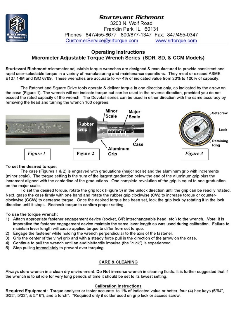
5. Grip the center of the handle and with a steady force, pull in the direction of the arrow on the case.
6. Continue to pull the wrench until an audible/tactile impulse (the “click”) is experienced.
7. Stop pulling immediately to prevent over torque application.
Required Equipment For Calibration:
Torque analyzer or tester accurate to 1% of indicated value or better, ve (5) hex keys (7/64”, 5/64”, 3/32”,
5/32”, & 5/16”). Torque wrench set to 15 Ft. Lbs. (20.4 Nm) with 5/16 hex bit socket.
Test and Calibration Procedure Instructions
To determine the current performance compared to standard test the wrench on a torque analyzer or tester.
A mechanical loader is always preferred and the test equipment must maintain at least a 4:1 ratio meaning
that the tester must be at least 4 times more accurate than the tool being tested.
Prior to testing use the following procedure to assess wrench condition:
A. Cycle the wrench a minimum of three (3) times at 100% of wrench capacity.
B. Set wrench to 20% of rated capacity, cycle three (3) times and record readings.
C. Set wrench to 60% of capacity, cycle three (3) times and record readings.
D. Set wrench to 100% of capacity, cycle three (3) times and record readings.
Compare test results to required tolerance at each level. If the wrench is within tolerance it may be returned
to service. If the wrench is out of tolerance calibrate the wrench.
To Calibrate the Wrench:
1. Remove tang access screw as shown in the image to the right.
NOTE: Tools with capacity of 100 Ft. Lbs or 140 Nm or more
have two (2) 5/64” set screws. The rst set screw is a jam
screw and must be removed in order to make the adjustment to
the tang adjusting screw. The rst set screw must be reinstalled
at the end of calibration to ensure the wrench holds torque.
2. Remove the lock control knob and hex stem.
3. Rotate the aluminum grip to 100% of capacity (highest graduation +0 on increment)
4. Place wrench on tester. Click several times and note readings.
5. Adjust wrench.
5.1 If readings are above tolerance, turn tang adjustment screw slightly clockwise. (CW) Repeat Step 4.
5.2 If readings are below tolerance, turn tang adjustment screw slightly CCW. Repeat Step 4.
5.3 If readings are within tolerance go to next step.
Part # 857451
March 8, 2017Rev B
