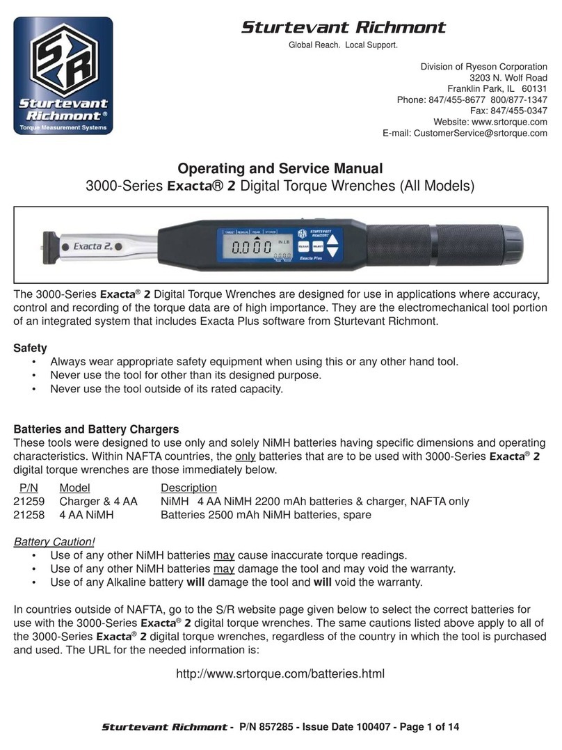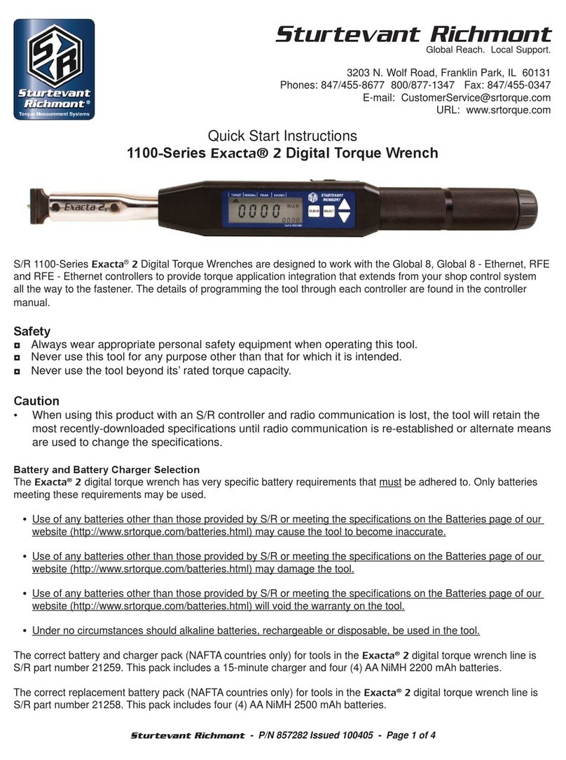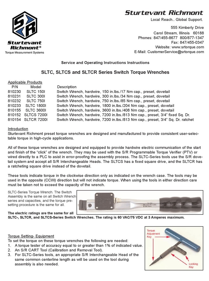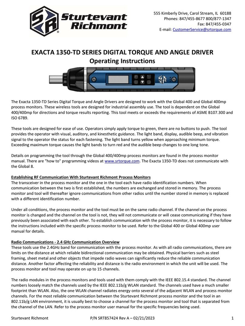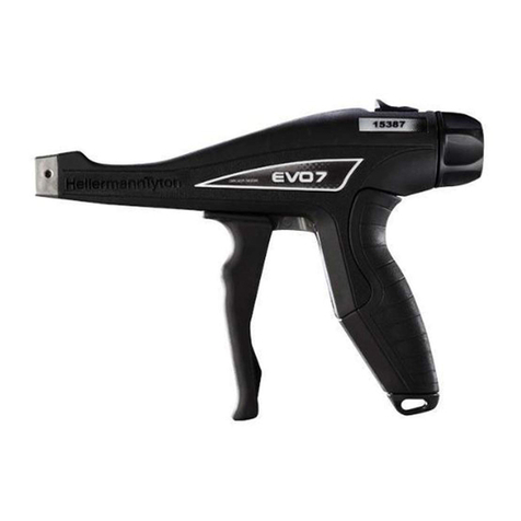
Procedure (Refer to Figures 1 through 4 for component location and nomenclature):
1) Determine current performance to standard.
a) Test wrench on torque analyzer/tester.
i) Cycle wrench at 50% of capacity a minimum of three times.
ii) Set wrench to 20% of capacity, cycle three (3) times and record readings.
iii) Set wrench to 60% of capacity, cycle three (3) times and record readings.
iv) Set wrench to 100% of capacity, cycle three (3) times and record readings.
b) Compare readings to tolerance for each torque level.
i) If wrench is within tolerance, it may be returned to service.
ii) If wrench is out-of-tolerance, go to next step.
2) Calibrate wrench.
a) Remove rubber grip.
b) If solder was used to preclude access to grip lock and or access screw, remove solder. Do NOT touch grip, grip
lock, or screw until cool. If solder not used, go directly to next step.
c) Remove access screw.
d) Loosen setscrew in grip lock until it protrudes approximately 1/8” above top of lock.
e) Depress grip lock to remove pressure on retaining ring.
f) Remove retaining ring.
g) Remove grip lock and hex stem lock.
h) Rotate aluminum grip to 100% of capacity (highest graduation + 0 on increment).
i) Place wrench on torque analyzer/tester, click several times, note values obtained.
j) Adjust wrench.
i) If readings are above tolerance, turn tang adjustment screw slightly CW, then repeat step 2i.
ii) If readings are below tolerance, turn tang adjustment screw slightly CCW, then repeat step 2i.
iii) If readings are in tolerance, go to next step.
k) Rotate grip and adjust torque to 20% of capacity (lowest graduation + 0 on increment).
l) Place wrench on torque analyzer/tester, click several times, note values obtained.
i) If out-of-tolerance, go to next step.
ii) If in tolerance, check at 60% and 100% of capacity.
m) Rotate grip CW or CCW enough clicks to bring into tolerance at 20% of scale.
n) Lock load screw by rotating internal 5/32” internal hex screw in the CCW direction.
o) Use 5/16” hex key to remove lock plug by rotating in the CCW direction.
p) Rotate grip until it aligns with lowest graduation (20% of capacity).
q) Replace lock plug and unlock load screw.
r) Return to step 2h.
s) Replace hex stem, grip lock, and retaining ring.
t) Tighten setscrew in grip lock until it lightly touches bottom, then back off ¾ to 1 turn.
u) Replace access screw and rubber grip.
REPAIR PARTS, SERVICE, & CALIBRATION
Repair parts can be ordered through your local S/R distributor. For the name of a local S/R distributor, please contact us
using the information on the front of this document. Factory repair and NIST-traceable certification, can be obtained by
sending the wrench and your instructions to us at the factory address on the front of this sheet.
CAUTION
1. Safety glasses should be worn when using any hand tool. 2. Never exceed the rated torque of the tool.
3. Assure fastener engagement device properly engages fastener. 4. Never use cheater bars to increase leverage.
5. Use hand tools only for their intended purpose.
857046-F
Figure 4
