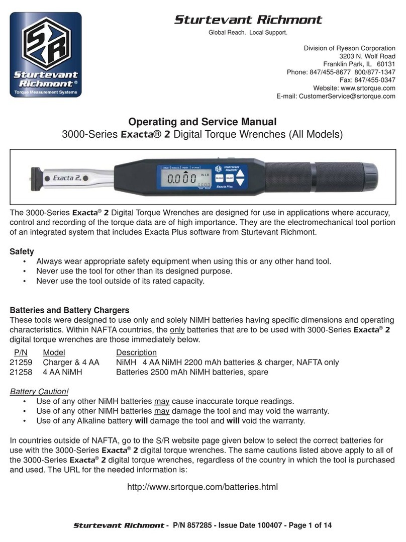
Sturtevant Richmont exacta 2 Programming manual

Sturtevant Richmont - P/N 857282 Issued 100405 - Page 1 of 4
Sturtevant Richmont
Global Reach. Local Support.
3203 N. Wolf Road, Franklin Park, IL 60131
Phones: 847/455-8677 800/877-1347 Fax: 847/455-0347
E-mail: [email protected]
URL: www.srtorque.com
Quick Start Instructions
1100-Series Exacta® 2 Digital Torque Wrench
S/R 1100-Series Exacta®2Digital Torque Wrenches are designed to work with the Global 8, Global 8 - Ethernet, RFE
and RFE - Ethernet controllers to provide torque application integration that extends from your shop control system
all the way to the fastener. The details of programming the tool through each controller are found in the controller
manual.
Safety
◘Always wear appropriate personal safety equipment when operating this tool.
◘Never use this tool for any purpose other than that for which it is intended.
◘Never use the tool beyond its’ rated torque capacity.
Caution
• When using this product with an S/R controller and radio communication is lost, the tool will retain the
most recently-downloaded specifications until radio communication is re-established or alternate means
are used to change the specifications.
Battery and Battery Charger Selection
The Exacta®2 digital torque wrench has very specific battery requirements that must be adhered to. Only batteries
meeting these requirements may be used.
•Use of any batteries other than those provided by S/R or meeting the specifications on the Batteries page of our
website (http://www.srtorque.com/batteries.html) may cause the tool to become inaccurate.
•Use of any batteries other than those provided by S/R or meeting the specifications on the Batteries page of our
website (http://www.srtorque.com/batteries.html) may damage the tool.
•Use of any batteries other than those provided by S/R or meeting the specifications on the Batteries page of our
website (http://www.srtorque.com/batteries.html) will void the warranty on the tool.
•Under no circumstances should alkaline batteries, rechargeable or disposable, be used in the tool.
The correct battery and charger pack (NAFTA countries only) for tools in the Exacta®2digital torque wrench line is
S/R part number 21259. This pack includes a 15-minute charger and four (4)AANiMH 2200 mAh batteries.
The correct replacement battery pack (NAFTA countries only) for tools in the Exacta®2digital torque wrench line is
S/R part number 21258. This pack includes four (4)AANiMH 2500 mAh batteries.

Sturtevant Richmont - P/N 857282 Issued 100405 - Page 2 of 4
For countries outside NAFTA, consult the batteries page on our website (http://www.srtorque.com/batteries.html) to
find the correct battery and battery charger for use in your country. Follow the manufacturer links provided and select
the appropriate product for your country and need.
S/R Dovetail and Interchangeable Heads
Those models of the Exacta®2digital torque wrench that are equipped with an S/R dovetail are designed to be used
with S/R interchangeable heads. The dovetail design provides an exceptionally strong and rigid connection.
The Exacta®2 models with the dovetail are calibrated for use with S/R interchangeable heads having a 1 7/16”
Common Centerline Length (CCL). Use of interchangeable heads with a different CCL or head extension(s) will
make the tool inaccurate until and unless it is recalibrated with a head having the same CCL as that which has been
selected for use. Always recalibrate the tool immediately if changing to a head with a different CCL or if a head
extension is to be used.
Ratchets
Some Exacta®2 models have ratcheting square drives instead of the S/R dovetail. These are slide pin ratchets
capable of being set to ratchet in either the clockwise (CW) or counter-clockwise (CCW) direction. To change the
ratcheting direction, remove all torque load from the tool and push the slide pin to the opposite side from that to which
it is currently biased.
The ratchet should be disassembled, cleaned and lubricated periodically. The procedure for performing this function
can be found in the FAQ section of our website. See the Ratchet Replacement procedure (FAQ 7) and simply clean
and replace the original parts instead of installing new parts. If the ratchet is damaged, contact your S/R distributor
and order the correct ratchet renewal kit for your tool, then use the instructions on the website to perform the
replacement.
Component Identification
1. Electronics Module
The electronics module houses and protects the circuit boards, display, operating buttons and other electronic
components.
2. Display
The display conveys the visual information needed for use and generated by use.
3. Indicator Labels
These labels, working with indicators on the display, inform the user what mode or function is currently active.
4. Buttons
These buttons (Clear, Select, Up, Down) are used to access program functions and data on the display.
5. Grip
The grip is where the tool should be grasped when in use. The load point on the grip is marked by the plain ring in
the center of the grip.
6. Battery Compartment Cover
The battery compartment cover protects the batteries and associated parts, and permits access for battery
replacement.

Sturtevant Richmont - P/N 857282 Issued 100405 - Page 3 of 4
7. Switch Cover
This rubber cover protects the power switch and the serial port.
8. Serial Port
This is a single-pin serial port for communications.
9. Power Switch
This switch enables and disables electric power from the batteries to the
electronics.
10. Indicators
There are four triangular indicators in a line across the top of the display. These indicators are activated and
deactivated to show what mode or operation is currently active on the tool. To the right of these is a battery icon
(not activated in this photograph) used as a battery level (low battery power) indicator.
11. Unit of MeasureArea
This area of the display shows the
currently active unit of measure,
both during use and during
keyboard programming.
12. Data Record Area
This small four-digit display shows
the currently-active data record in
memory or, when programming, part
of the function information required. When in radio contact, it displays “rAd”.
13. Quality Attribute Area
There are several icons along the bottom of the display to the left of the Data Record area. These include “OK”
and “BAD”, which provide the attribute evaluation of the torque against the programmed specification when the
tool is in use. They also include MAX and MIN
14. CCW Icon
The CCW icon illuminates when the torque is in the counter-clockwise direction.
15. Primary Display Area
The primary display area conveys differing information depending upon the current action of the tool. This may be
numeric information such as torque values or alphabetic information such as is used in some programming and
communication functions.
16. Rear Cover
The radio cover permits access to the electronics when repair is required; it should not be removed except for
repair situations requiring its’ removal.
17. Rear LED Lens
This lens illuminates with the color (Yellow-Orange/Green/Red) in the same manner as the display when the LED
color system is in use. This permits the user to know the status of the tightening even when the tool is used in an
orientation where the display is not immediately visible.
18. Buzzer
This buzzer provides an audible indication of the torque status to augment the visual indicators. When in use, the
buzzer emits a single sound when power to the tool is enabled, a rapid series of beeps when the torque specifi-
cation is attained and while within the specification. It will emit a single longer beep if the torque specification or
torque capacity is exceeded.

Sturtevant Richmont - P/N 857282 Issued 100405 - Page 4 of 4
Battery Installation
To install the batteries in the tool:
1. Move the power switch to the disabled (off) position.
2. Unscrew the battery cover from the rear of the grip.
3. Observe the two labels inside on the battery holder.
4. Install the batteries as shown on the labels and in the
photograph here.
5. Reinstall the battery cover.
Starting Routine
To use the wrench slide the power switch to the Enabled or On position. The tool will begin an internal starting routine
and the display will first show the version of the firmware that resides on the tool then display the model of the tool
(tool capacity in foot-pounds).
Once the starting routine is complete, the tool will then show on the display the information for the status in which it
was most recently set. This includes the mode of operation, unit of measure, current data record number and target
torque setting.
If the tool has been associated with or learned by a controller, the lower right-hand corner of the display will have the
characters “rad” active.
The Controller Association or Learning Process
Each of the controllers these tools can be used with has a different learning process, and the instructions for creating
the association for each is slightly different. There are a couple of common elements in the process:
• The process will start with the tool power disabled (tool turned off)
• The controller will be placed into a “learning” mode or the tool transmitter serial number will be provided to the
controller.
• At the point in the process where the actual association is to be created, the tool power will be enabled (power
turned on).
During this process the controller and tool will establish the communication link, and the controller will notify the
operator or programmer that the association has been made, usually through a sound or LED illumination. Once
this process is complete, the options for tool programming through the controller and tool use with the controller are
available.
Using the Tool Without a Controller
S/R 1100-Series Exacta®2Digital Torque Wrenches can be used without a controller when needed, but the operating
characteristics are significatly different; the tool functions as a standard Exacta®2Digital Torque Wrench. Additional
information on this is available on our website, along with calibration instructions and Exawin 5 software. All of these
are available at no charge; simply register your tool(s) by following the links on the Exacta®2page and follow the
instructions to download all of the available options.
Cleaning, Calibration and Repair
These tools should be cleaned periodically with a soft damp cloth to remove dirt.
Factory calibration (with certification from our ISO 17025 Accredited Laboratory) is available, as is factory repair
if needed. Simply contact your S/R distributor, or contact us directly using the information on the first page of this
document.
Other manuals for exacta 2
2
Table of contents
Other Sturtevant Richmont Power Tools manuals

Sturtevant Richmont
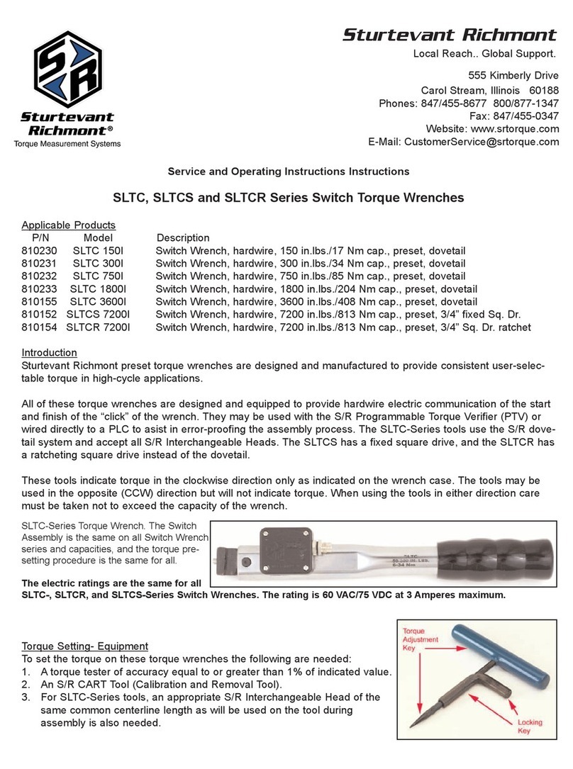
Sturtevant Richmont LTCR Series User manual
Sturtevant Richmont
Sturtevant Richmont SLTC Series Operating instructions
Sturtevant Richmont
Sturtevant Richmont SD Series User manual
Sturtevant Richmont
Sturtevant Richmont SLTC-FM 2.4GHz Series User manual

Sturtevant Richmont
Sturtevant Richmont exacta 2 Service manual

Sturtevant Richmont
Sturtevant Richmont SLTCR-FM 2.4GHz 3000I User manual
Sturtevant Richmont
Sturtevant Richmont EXACTA 1350-TD Series User manual

Sturtevant Richmont
Sturtevant Richmont exacta 2 User manual

Sturtevant Richmont
Sturtevant Richmont DTC User manual
Sturtevant Richmont
Sturtevant Richmont SDR Series User manual
