Subzero 424 User manual

INSTALLATION GUIDE
Wine Storage

Important Note
To ensure the safe and efficient installation of Sub-Zero
equipment, please take note of the following types of
highlighted information throughout this guide:
IMPORTANT NOTE highlights information that is
especially relevant to a problem-free installation.
CAUTION signals a situation where minor injury or
product damage may occur if instructions are not
followed.
WARNING states a hazard that may cause serious injury
or death if precautions are not followed.
Wine Storage Installation Guide
Contents
Wine Storage Equipment ....................... 3
Models 424 and 424FS Installation ............... 4
Models 427 and 427R Installation ............... 14
Model WS-30 Installation ...................... 26
Installation Checklist ......................... 50
Service Information .......................... 51
Features and specifications in this guide and on the website
are subject to change at any time without notice. Check our
website, subzero.com, for the most up-to-date specifications.

Wine Storage Equipment 3
subzero.com
Wine Storage Equipment
The importance of the installation of the Sub-Zero wine
storage unit cannot be overemphasized. Installation
should be done by a qualified installer.
Before you begin the installation process, it is recom-
mended that you read this entire installation guide. There
are key details that you should take special care to
observe during the installation. By reading these instruc-
tions carefully, you will make the installation process
easier, problem-free and, most importantly, safe.
Any questions or problems regarding the installation
should be directed to your Sub-Zero dealer or Sub-Zero
customer service at 800-222-7820. You may also check
the contact & support sectionofour website, subzero.com.
Important product information, including the model and
serial number of your unit are listed on the product rating
plate. For models 424 and 424FS, the rating plate is
located on the underside of the top wall. For models 427,
427R and WS-30, it is attached to the underside of the
control panel. Refer to the illustrations.
IMPORTANT NOTE: Throughout this guide, dimensions in
parentheses are millimeters unless otherwise specified.
Models 424 and 424FS.
RATING PLATE
Models 427, 427R and WS-30.
RATING PLATE

Models 424 and 424FS Installation 4
341/2"
(876)
ROUGH
OPENING
HEIGHT
341/4"
(870)
MINIMUM
HEIGHT
REQUIRED
ROUGH OPENING
WIDTH
24"(610) MODEL 424
243/8"(619) MODEL 424FS
151/2"
(394)
24"
(610)
ROUGH
OPENING
DEPTH
LOCATE ELECTRICAL
WITHIN SHADED AREA
E
41/2"
(114)
21/2"
(64)
237/8"
(606)
MODEL 424
ANTI-TIP BRACKET
MODEL 424FS
ANTI-TIP BRACKET
90˚
145˚
MAXIMUM
DOOR SWING
44" (1118)
DOOR CLEARANCE
26" (660)
DOOR CLEARANCE
253/8"
(644)
253/8"
(645)
FRONT VIEW
TOP VIEW
Models 424 and 424FS Installation
The Sub-Zero model 424FS wine storage unit is designed
to be attractive in a stand alone setting. It can also be slid
into surrounding cabinetry with clearance dimensions
slightly different than the standard built-in model 424.
Make sure that the finished rough opening where the wine
storage unit is to be installed is properly prepared. Refer
to the installation specifications illustration for rough
opening dimensions, door swing clearance and electrical
placement for models 424 and 424FS.
IMPORTANT NOTE: To operate properly, the door must
open a minimum of 90 . Use a minimum 3" (76) filler in
corner installations to assure a 90 door opening. Allow
enough clearance in front of the unit for full door swing.
IMPORTANT NOTE: Make sure the floor under the unit is
level with the surrounding finished floor.
Do not load wine into the wine storage unit until the
installation is complete.
Door swing clearances are based on stainless steel door and
handle dimensions.

Models 424 and 424FS Installation 5
subzero.com
Electrical Requirements
A115 V AC, 60 Hz, 15 amp circuit breaker and electrical
supply are required. A separate circuit, servicing only this
appliance, is required.
The power supply cord has a 3-prong grounding plug,
which must be plugged into a mating 3-prong grounding-
type wall receptacle. Follow the National Electrical Code
and local codes and ordinances when installing the recep-
tacle. For location of the electrical supply, refer to the
installation specifications illustration on the previous page.
IMPORTANT NOTE: For models 424 and 424FS, the elec-
trical outlet must be placed so the grounding prong is to
the right of the thinner blades. The outlet must be flush
with the back wall.
IMPORTANT NOTE: A ground fault circuit interrupter
(GFCI) is not recommended and may cause interruption of
operation.
HOME ALARM SYSTEM
If a home alarm system is to be used, refer to home alarm
connections on page 9. In addition to operating power, the
installer may also be required to supply a home automa-
tion system lead to the unit. This is for a low-voltage, low-
current signal similar to door and window sensor signals.
Common, normally open and normally closed contact
configurations are provided.
Three 1/4" (6) female spade connectors are located in the
compressor compartment and are accessible behind the
kickplate on models 424 and 424FS. A minimum of 36"
(914) of lead wire should be provided for each contact,
exiting the back wall near the electrical outlet.
npacking and Moving
Uncrate the unit, remove its wood base and discard the
shipping bolts that hold the wood base to the bottom of
the unit. Remove all packing materials and tape.
IMPORTANT NOTE: Do not discard the kickplate, anti-tip
bracket and hardware. These items will be needed for the
installation.
All roller-assembly wine shelves should be removed to
reduce weight and prevent them from rolling. To remove,
pull the shelf out to its full extension, gently and evenly lift
up on both sides of the front of the shelf and remove.
Reverse the procedure to reinstall the shelf.
Use an appliance dolly to move the wine storage unit.
Position the dolly at the back of the unit to prevent
damage to finished surfaces.
Before moving the wine storage unit in to position,
protect any finished flooring with appropriate mate-
rials and secure the door closed.
Do not use an extension cord or two-prong adapter.
Electrical ground is required on this appliance.

Anti-Tip Bracket Installation
MODEL 424FS
If you are installing the model 424FS in a space deeper
than 245/8" (625), the anti-tip bracket must be installed no
more than 245/8" (625) deep, so it engages the unit
properly. It is important that this measurement be made
from the front surface of the door, to the back of the anti-
tip bracket. Refer to the illustration.
An anti-tip bracket and hardware is provided with the wine
storage unit. The anti-tip bracket must be installed on a
solid base to prevent tipover in case several loaded wine
shelves are extended at the same time.
MODEL 424
The anti-tip bracket should be attached to the wall behind
the unit with the bracket flange located immediately above
the top of the unit. Refer to the illustration below.
A smaller metal ‘countertop’ bracket is also provided with
the model 424, for installations that need to be modified to
provide a secure surface for attaching the bracket. This
bracket will secure the front of the unit to the underside of
the countertop, above the unit. Refer to the illustration
below.
Models 424 and 424FS Installation 6
1/4"(6)
ANTI-TIP
BRACKET
Anti-tip bracket—model 424. Countertop bracket
COUNTERTOP
BRACKET
To prevent the unit from tipping forward and provide
a stable installation, the unit must be secured in
place with the anti-tip bracket.
ANTI-TIP BRACKET
Anti-tip bracket—model 424FS.

Anti-Tip Bracket Installation
WOOD FLOOR APPLICATIONS
Use the four #12 x 21/2" wood screws and the four 1/4"
flat washers provided. Drill pilot holes 3/16" (5) diameter
maximum, and be sure that the screws penetrate through
the flooring material and into the wall plate a minimum of
3/4" (19). Be sure that the screws hold tight. Refer to the
illustration below.
CONCRETE FLOOR APPLICATIONS
Use the two 3/8" x 33/4" concrete wedge anchors, two
#12 x 21/2" wood screws and two 1/4" flat washers
provided. Be sure that the anchors and screws hold tight.
Refer to the illustration below.
IMPORTANT NOTE: In some installations the subflooring
or finished floor may require angling the wood screws
used to fasten the anti-tip bracket to the back wall.
INSTALLATION FOR CONCRETE WEDGE ANCHORS
1) Drill a 3/8" (10) diameter hole any depth exceeding the
minimum embedment. Clean the hole or continue
drilling additional depth to accommodate drill fines.
Use a carbide drill bit manufactured within ANSI
B94.12-77.
2) Assemble the washer and nut flush with the end of
anchor to protect threads. Drive the anchor through the
material to be fastened until the washer is flush with
the surface material.
3) Expand the anchor by tightening the nut 3–5 turns past
hand-tight position or to 25 foot-pounds of torque.
Models 424 and 424FS Installation 7
subzero.com
Always wear safety glasses and use other necessary
protective devices or apparel when installing or
working with anchors.
Anchors are not recommended for use in lightweight
masonry material such as block or brick, or for use
in new concrete which has not had sufficient time to
cure. The use of core drills is not recommended to
drill holes for the anchors.
Make sure that there are no electrical wires in the
area which the screws could penetrate.
12 3/16"
(310)
12 3/16"
(310)
24"
(610)
C
L
FINISHED FLOORING
UNDERLAYMENT
WALL PLATE
SUBFLOORING
WOOD FLOOR
Wood floors. Concrete floors.
24"
(610)
C
L
11/2"
min
(38)
12 3/16"
(310)
12 3/16"
(310)
FINISHED FLOORING
UNDERLAYMENT
WALL PLATE
SUBFLOORING
CONCRETE
FLOOR

Models 424 and 424FS Installation 8
Lock Installation
IMPORTANT NOTE: If you are adding an accessory lock kit
to your wine storage unit, it should be installed before you
position the unit. Installation instructions are included with
the lock kit.
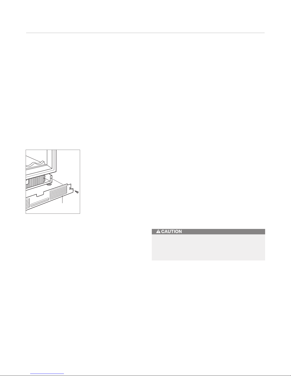
For model 424, the lock is attached to the bottom of the
metal door frame. The decorative door panel is not
involved in the installation or operation of the lock. The
catch portion of the lock is attached to the bottom of the
appliance cabinet in pre-punched holes. When installing
the lock kit, it may be helpful to tip the unit on its back for
easier access.
POSITION THE UNIT
IMPORTANT NOTE: If for any reason the wine storage unit
has been laid on its back or side, you must allow the unit
to stand upright for a minimum of 24 hours before con-
necting power.
Plug the power supply cord into the 15 amp grounded
electrical outlet. With power applied to the appliance,
check for lighting and cooling before going any further.
Once you are satisfied that the unit is operating properly,
shut off power to the electrical outlet at the circuit breaker
and proceed.
If a home alarm system is to be used with the wine
storage unit, the lead wires should be threaded into the
compressor compartment before you position the unit.
Refer to home alarm connections on page 9, for the
location of these lead wires. After the unit is in position,
the alarm wiring can be completed from the front.
Pre-level the wine storage unit before sliding it into
position. Leveling cannot be completed with the unit
pushed back in the installation opening.
For model 424FS, adust the leveling legs so the top of the
unit is no more than 345/8" (879) above the floor. This is to
allow the unit to engage the anti-tip bracket properly.
Center the model 424FS in front of the anti-tip bracket.
Slide the unit into position, making sure the anti-tip
bracket is engaged properly.
IMPORTANT NOTE: When the wine storage unit is
installed, the anti-tip bracket will be positioned just below
the engaging bracket on the unit. It is not necessary to
raise the unit up so that it locks into the anti-tip bracket,
but the unit must be in alignment with the anti-tip bracket.
The wine storage unit provides the best access to its
contents when the front surface of the door panel extends
out from surrounding cabinets approximately 1/4" (6). For
model 424FS, if there are no surrounding cabinet surfaces
to gauge depth, slide the unit back until it engages the
anti-tip bracket.
IMPORTANT NOTE: The floor under the wine storage unit
must be at the same level as the surrounding finished floor
to allow for removal of the unit for servicing.
Shut off the power to the electrical outlet.

Level the nit
Using an adjustable wrench or pliers, turn each of the four
leveling legs clockwise to raise the unit and counterclock-
wise to lower the unit. Refer to the illustration below for
location of the leveling legs.
For model 424, the countertop bracket should be used
to make a solid installation. Refer to the illustration on
page 6. If this is not possible, wedge shims along the
sides and top.
Home Alarm Connections
Before the kickplate is installed, all necessary wiring
connections in the compressor compartment should be
completed.
If a home alarm system is to be installed on the wine
storage unit, the connections should be made using the
logic supplied with the alarm specifications. Refer to the
illustration for the appliance lead locations, and refer to
the following for color codes:
•Normally open contacts – white with red stripe wire
•Normally closed contacts – white with blue stripe wire
•Common – gray with white stripe wire
Use the 1/4" (6) spade terminals or wire nuts provided to
make the proper wiring connections.
IMPORTANT NOTE: If you are not responsible for alarm
system connection, this information should be supplied to
the home security system contractor.
Models 424 and 424FS Installation 9
subzero.com
The alarm circuit in the unit is intended as a low-
voltage, low-current device only. It should not be
used to switch line power.
Any unused terminals should be completely insu-
lated and all wires should be secured away from
conductive or moving components.
To reduce the possibility of the unit tipping forward,
the front leveling legs must be in contact with the
floor.
LEVELING LEGS
Leveling legs. Home alarm connections.
HOME ALARM
CONNECTIONS

Kickplate Installation
Once the unit is leveled and wiring connections made, the
kickplate can be installed. Use the two #10 x 1/2" stain-
less steel screws that are provided with the kickplate.
Refer to the illustration below.
IMPORTANT NOTE: The kickplate must be removed for
servicing. The floor cannot interfere with removal. The
louvered section of the kickplate must not be covered so
as to prevent air circulation.
Turn power back on to the electrical outlet.
Door Panel—Model 424
Model 424 is offered in two design applications; stainless
steel (/S) and overlay (/O). Each of these designs are avail-
able as a glass door (G) model.
The stainless steel model 424/S is available as a glass
door (G) model only, with the classic finish and is shipped
from the factory with the decorative stainless steel door
panel and matching handle in place.
The overlay model 424/O is available as a glass door (G)
or solid door (S) model and is designed to accept a
decorative door panel to match surrounding cabinetry.
The door panel and the handle will be provided by the
customer.
Before beginning installation, check for the correct com-
ponents for the fit and finish desired. All overlay doors
require a decorative panel 233/4" (603) by 301/16" (764) and
a minimum 5/8" (16) thick.
IMPORTANT NOTE: For installations at or above 5,000'
(1524 m) in altitude, a special high altitude glass door unit
(HA) must be ordered.
If you have questions, contact your Sub-Zero dealer or
cabinet supplier. Additional panel information can be
found in the Sub-Zero design guide.
Models 424 and 424FS Installation 10
KICKPLATE
Kickplate installation.
A solid panel must not be installed on a glass door
unit, as this may cause moisture to form behind the
panel.

Overlay Door Panel—Model 424
Inspect the door panel for the minimum 5/8"(16) thickness,
the finished inside edge. The glass door has a 10 lbs (5 kg)
weight limit and the solid door has a 20 lb (9 kg) weight
limit. Refer to the wine storage section of the Sub-Zero
design guide for additional panel information.
Decide if the handle will be attached through the glass
door frame or just through the decorative door panel. If it
is just through the door panel, the handle must be
attached first.
Decorative panels are attached to the model 424 door
using #8 x 5/8" square drive screws passing through the
door frame from the rear, behind the gasket into the panel.
The door panel is marked for screw locations by the use of
‘tenon centers’, which are temporarily inserted into the
1/4" (6) diameter holes in the front of the glass door frame.
Refer to the illustration below.
With the wine storage unit secured in position and the
door closed, the panel is held in the desired position on
the door and rapped by hand from the front, putting center
marks on the rear surface of the panel. If the door panel is
made of such a material that pre-drilling is needed, all of
the mounting holes should be marked. If not, only enough
holes to hold the panel in place temporarily, are necessary.
The door panel is then lowered from the door frame, tenon
centers removed, the door opened and the screws driven
into the panel through the black tape on the door frame,
using the center marks to locate the screws.
The screw holes inside the door are hidden under a cover
flap on the door gasket. It is necessary to lift the flap to
insert the screws. Use as many screws as necessary to
hold the door panel in place properly.
IMPORTANT NOTE: After the first three or four mounting
screws are in place, but not completely tightened, close
the door and check your panel fit. This is the time to make
small adjustments. Once you are satisfied with the appear-
ance, open the door and apply the remainder of the
screws. Check all screws for tightness.
The metal frame on the glass door has numerous
mounting holes on each side of the door. This is to accom-
modate the Sub-Zero accessory handles and provide for
easy attachment of the handle through the door frame.
If you choose not to use the pre-drilled handle mounting
holes, it will be necessary to fasten the handle from the
rear of the door panel only, or drill one or more additional
holes through the metal frame of the glass door.
The cross section illustration shows how this hole passes
through the door frame. The hole center is on the small
locator groove in the front of the frame. A 1/4" (6) diameter
hole is made in the front wall of the extrusion and a 13/32"
(11) diameter hole through the rest of the frame.
Models 424 and 424FS Installation 11
subzero.com
Overlay panel. Door frame cross section.
GASKET
GLASS
13/32"(11)
DIAMETER
1/4"(6)
DIAMETER
OVERLAY
PANEL
DOOR
FRAME
TENON CENTER

Models 424 and 424FS Installation 12
Overlay Door Panel—Model 424
IMPORTANT NOTE: Install screws in all the mounting holes
in the door frame. The nature of the door panel with a
narrow outer rim and no connecting center member
requires the support provided by the glass door.
After the door panel installation is complete, apply the
cover patches or plugs provided over the holes on the
inside surface of the door.
The cover patches or plugs are part of the insulation
system on the door of the wine storage unit. Be sure
to cover all the holes in the door that were used.
The wine storage unit door is made with a sealed
double wall tempered glass core. The drill must not
contact this core when drilling. Be sure the hole is
centered on the small groove in the front of the door
frame and the drill passes squarely through the
frame. If you are inexperienced with drilling, fasten
the handle from the rear of the door panel only.

Hinge Adjustment
IMPORTANT NOTE: The wine storage unit must be
installed and leveled before door hinge adjustments can
be made.
The top and bottom cabinet hinges on models 424 and
424FS are held in place with three permanent adjustment
screws and two shipping screws. Refer to the illustrations
below. The shipping screws must be removed and dis-
carded to adjust the door alignment and fit. If no adjust-
ments are necessary, it is recommended that all five
screws remain in place.
On the model 424FS, only the bottom door hinge can be
adjusted. Remove and discard the two shipping screws
and loosen the three hinge screws to adjust the door.
Refer to illustration 12.
Models 424 and 424FS Installation 13
subzero.com
Completing the Installation
IMPORTANT NOTE: When you have completed the instal-
lation of the model 424 or 424FS wine storage unit, refer
to page 50 for an installation checklist and page 51 for
service information.
TOP DOOR HINGE
SHIPPING
SCREWS
Top hinge. Bottom hinge.
BOTTOM
DOOR HINGE
SHIPPING
SCREWS

Models 427 and 427R Installation 14
27"
(686)
ROUGH OPENING WIDTH
25"
(635)
ROUGH
OPENING
DEPTH
237/8"
(606)
90˚
105˚
MAXIMUM
DOOR SWING
35" (889)
DOOR CLEARANCE
28" (711)
DOOR CLEARANCE
251/2"
(648)
251/2"
(648)
151/2"
(394)
LOCATE ELECTRICAL
WITHIN SHADED AREA
E
41/2"
(114)
21/2"
(64)
ANTI-TIP BRACKET
FRONT VIEW
TOP VIEW
80" (2032)
ROUGH OPENING
HEIGHT
TOFINISHED
FLOORING
791/2"(2019)
MIN HEIGHT
REQUIRED
Models 427 and 427R Installation
Make sure that the finished rough opening where the wine
storage unit is to be installed is properly prepared. Refer
to the installation specifications illustration for rough
opening dimensions, door swing clearance and electrical
placement for models 427 and 427R.
IMPORTANT NOTE: To operate properly, the door must
open a minimum of 90 . Use a minimum 2" (51) filler in
corner installations to assure a 90 door opening. Allow
enough clearance in front of the unit for full door swing.
IMPORTANT NOTE: Make sure the floor under the unit is
level with the surrounding finished floor.
Do not load wine into the wine storage unit until the
installation is complete.
Door swing clearances are based on stainless steel door and
handle dimensions.

Models 427 and 427R Installation 15
subzero.com
Electrical Requirements
A115 V AC, 60 Hz, 15 amp circuit breaker and electrical
supply are required. A separate circuit, servicing only this
appliance, is required.
The power supply cord has a 3-prong grounding plug,
which must be plugged into a mating 3-prong grounding-
type wall receptacle. Follow the National Electrical Code
and local codes and ordinances when installing the recep-
tacle. For location of the electrical supply, refer to the
installation specifications illustration on the previous page.
IMPORTANT NOTE: For models 427 and 427R, the elec-
trical outlet must be placed so the grounding prong is to
the right of the thinner blades. The outlet must be flush
with the back wall.
IMPORTANT NOTE: A ground fault circuit interrupter
(GFCI) is not recommended and may cause interruption of
operation.
Before moving the wine storage unit into position,
protect any finished flooring with appropriate
materials.
Do not use an extension cord or two-prong adapter.
Electrical ground is required on this appliance.
HOME ALARM SYSTEM
If a home alarm system is to be used, refer to wiring
connections on page 20. In addition to operating power,
the installer may also be required to supply a home
automation system lead to the unit. This is for a low-
voltage, low-current signal similar to door and window
sensor signals. Common, normally open and normally
closed contact configurations are provided.
Three 1/4" (6) female spade connectors are located in the
compressor compartment and are accessible behind the
kickplate/grille on models 427 and 427R. A minimum of
36" (914) of lead wire should be provided for each contact,
exiting the back wall near the electrical outlet.
npacking and Moving
Uncrate the unit, remove its wood base and discard the
shipping bolts that hold the wood base to the bottom of
the unit. Remove all packing materials and tape.
IMPORTANT NOTE: Do not discard the kickplate/grille,
anti-tip bracket and hardware. These items will be needed
for the installation.
All roller-assembly wine shelves should be removed to
reduce weight and prevent them from rolling. To remove,
pull the shelf out to its full extension, gently and evenly lift
up on both sides of the front of the shelf and remove.
Reverse the procedure to reinstall the shelf.
Retract the front leveling legs to allow you to move the
unit more easily during installation. You will extend the
leveling legs when the unit is in its final position to reduce
the possibility of the unit tipping forward.
Use an appliance dolly to move the wine storage unit.
Position the dolly at the side of the unit to prevent damage
to finished surfaces.

Models 427 and 427R Installation 16
Anti-Tip Bracket Installation
An anti-tip bracket and hardware is provided with the wine
storage unit. The anti-tip bracket must be installed on a
solid base to prevent tipover in case several loaded wine
shelves are extended at the same time.
If you are installing the model 427 or 427R in a space
deeper than 24" (610), the anti-tip bracket must be
installed no more than 24" (610) deep, so it engages the
unit properly. It is important that this measurement be
made from the front of the unit without panels, to the back
of the anti-tip bracket.
WOOD FLOOR APPLICATIONS
Use the six #12 x 21/2" wood screws and the six 1/4" flat
washers provided. Drill pilot holes 3/16" (5) diameter
maximum, and be sure that the screws penetrate through
the flooring material and into the wall plate a minimum of
3/4" (19). Be sure that the screws hold tight. Refer to the
illustration below.
CONCRETE FLOOR APPLICATIONS
Use the two 3/8" x 33/4" concrete wedge anchors, two
#12 x 21/2" wood screws and two 1/4" flat washers
provided. Be sure that the anchors and screws hold tight.
Refer to the illustration below.
IMPORTANT NOTE: In some installations the subflooring
or finished floor may require angling the wood screws
used to fasten the anti-tip bracket to the back wall.
To prevent the unit from tipping forward and provide a
stable installation, install the anti-tip bracket and
extend the front leveling legs to the floor.
WOOD FLOOR
Finished Flooring
Underlayment
Subflooring
Wall Plate
Wood floors—
dimension A is 131/2" (343).
Concrete floors—
dimension A is 131/2" (343).
Finished Flooring
Underlayment
Subflooring
Wall Plate
CONCRETE
FLOOR
11/2"
min
(38)
Make sure that there are no electrical wires in the
area which the screws could penetrate.

Models 427 and 427R Installation 17
subzero.com
Anti-Tip Bracket Installation
CONCRETE WEDGE ANCHOR INSTALLATION
1) Drill a 3/8" (10) diameter hole any depth exceeding the
minimum embedment. Clean the hole or continue
drilling additional depth to accommodate drill fines.
Use a carbide drill bit manufactured within ANSI
B94.12-77.
2) Assemble the washer and nut flush with the end of
anchor to protect threads. Drive the anchor through the
material to be fastened until the washer is flush with
the surface material.
3) Expand the anchor by tightening the nut 3–5 turns past
hand-tight position or to 25 foot-pounds of torque.
Position nit
IMPORTANT NOTE: For model 427R, the top drawer has a
control cable that needs to be disconnected before
removing this drawer. Refer to illustration 3 below for
placement and how to disconnect this fitting.
For model 427R, the drawers should be placed aside until
you are ready for installation of the door and drawer
panels.
IMPORTANT NOTE: When two models 427, 427R or
integrated units are installed closer than 2" (51) to one
another, it is necessary to use the Sub-Zero dual installa-
tion heater kit. The heater from this kit must be attached
to the left side exterior of the right-hand unit before the
unit is slid into position. The dual installation heater kit and
additional instructions is available through your Sub-Zero
dealer, or call Sub-Zero at 800-222-7820. You can also
visit our website at subzero.com.
Always wear safety glasses and use other necessary
protective devices or apparel when installing or
working with anchors.
Anchors are not recommended for use in lightweight
masonry material such as block or brick, or for use
in new concrete which has not had sufficient time to
cure. The use of core drills is not recommended to
drill holes for the anchors.
Control cable.

Lock Installation
For models 427 and 427R, the optional lock is attached
to the decorative door panel through a field-drilled hole in
the panel. The catch should be installed on the top of
appliance cabinet before the unit is moved into position.
The accessory lock kit and additional instructions are
available through your Sub-Zero dealer, or call Sub-Zero
at 800-222-7820. You can also visit our website at
subzero.com.
IMPORTANT NOTE: For accessory stainless steel panels
requiring a lock, panels must be ordered with the lock
mounting hole pre-drilled.
Position the nit
Remove the decorative top and side moldings and the
kickplate/grille of the wine storage unit.
IMPORTANT NOTE: If for any reason the wine storage unit
has been laid on its back or side, you must allow the unit
to stand upright for a minimum of 24 hours before con-
necting power.
Plug the power supply cord into the 15 amp grounded
electrical outlet. With power applied to the appliance,
check for lighting and cooling before going any further.
Once you are satisfied that the unit is operating properly,
shut off power to the electrical outlet at the circuit breaker
and proceed.
Models 427 and 427R Installation 18
If a home alarm system is to be used with the wine
storage unit, the lead wires should be threaded into the
compressor compartment before you position the unit.
Refer to wiring connections on page 20 for the location of
these lead wires. After the unit is in position, the alarm
wiring can be completed from the front.
Pre-level the wine storage unit before rolling into position.
This is to allow the unit to engage the anti-tip bracket
properly.
Roll the unit into position, making sure the anti-tip bracket
is engaged properly. Screw the front leveling legs out
approximately 3/16" (5) to make any future adjustments
easier.
IMPORTANT NOTE: When the wine storage unit is
installed, the anti-tip bracket will be positioned just below
the engaging bracket on the unit. It is not necessary to
raise the unit up so that it locks into the anti-tip bracket,
but the unit must be in alignment with the anti-tip bracket.
IMPORTANT NOTE: The floor under the wine storage unit
must be at the same level as the surrounding finished floor
to allow for removal of the unit for servicing.
Shut off the power to the electrical outlet.

Models 427 and 427R Installation 19
subzero.com
Leveling
Level the unit by turning the front leveling legs clockwise
to raise the unit, or counterclockwise to lower it. To assist
you in adjusting the front leveling legs up or down, use a
standard screwdriver blade and place it in the front
leveling leg as shown in the illustration below.
The rear leveling legs are adjusted from the front of the
base by turning the Phillips head screw. Refer to the illus-
tration below.
IMPORTANT NOTE: The rear leveling legs will only move
1/16" (2) for every 18 revolutions on the Phillips head screw.
Do not over torque. Use the lowest torque setting on any
power screwdriver. Do not turn the rear leveling legs by
hand. Damage will occur if you turn these legs.
Install Molding
The decorative white molding strips for the top and sides
of models 427 and 427R can be snapped into place as
shown in the illustrations below. The top molding piece
must be installed before the side molding can be
attached. For installations where units are positioned side
by side, refer to side panels on page 25.
Front leveling leg adjustment. Rear leveling leg adjustment.
To reduce the possibility of the unit tipping forward,
the front leveling legs must be in contact with the
floor.
TOP MOLDING
Top molding installation.
Side molding installation.

Models 427 and 427R Installation 20
Wiring Connections
Before the kickplate/grille is installed, all necessary wiring
connections in the compressor compartment should be
completed.
If the dual installation heater kit (7007529) is used with
model 427 or 427R, the power supply leads should be
connected according to instructions included with the kit.
If a home alarm system is to be installed on the wine
storage unit, the connections should be made using the
logic supplied with the alarm specifications. Refer to the
illustration below for the appliance lead locations, and
refer to the following for color codes:
•Normally open contacts: white with red stripe wire.
•Normally closed contacts: white with blue stripe wire.
•Common: gray with white stripe wire.
Use the 1/4" (6) spade terminals or wire nuts provided to
make the proper wiring connections.
IMPORTANT NOTE: If you are not responsible for alarm
system connection, this information should be supplied to
the home security system contractor.
HOME ALARM
CONNECTIONS
Home alarm connections.
The alarm circuit in the unit is intended as a low-
voltage, low-current device only. It should not be
used to switch line power.
Any unused terminals should be completely insu-
lated and all wires should be secured away from
conductive or moving components.
This manual suits for next models
4
Table of contents
Other Subzero Wine Cooler manuals

Subzero
Subzero Classic Series User manual

Subzero
Subzero WS-30 User manual

Subzero
Subzero 400-2 SERIES User manual

Subzero
Subzero 400-2 SERIES User manual

Subzero
Subzero WOLF ICB WS Series User manual

Subzero
Subzero WOLF UW Series User manual

Subzero
Subzero CL3050W/O User manual

Subzero
Subzero UW-24 User manual