Overlay Panels
If your customer has chosen an overlay design applica-
tion, make sure that the panels you are about to install
match dimensions listed in the overlay panel specifica-
tions to the right. Additional panel design information can
be found in the Sub-Zero wine storage design guide and
on our website, subzero.com.
IMPORTANT NOTE: The size of the overlay panel is
critical. It must fit over the door frame. The weight of the
overlay panel must not exceed 34 kg and the panel must
be a minimum of 16 mm thick.
Overlay models are shipped without handle hardware. The
cabinet manufacturer or designer will need to provide
handle hardware to match the overall decorating scheme.
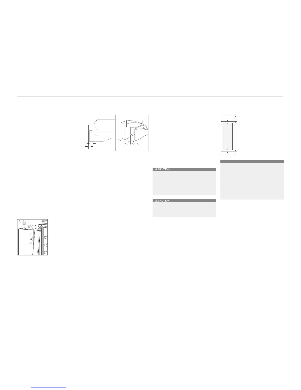
To install overlay panels, first remove the door trim
molding. Insert a screwdriver tip into the top corner slot on
the handle side and pop out the trim molding. Refer to the
illustration below. Remove the screws and frame.
Sub-Zero allows a 6 mm space to slide the backing
material into place in the frame. If your material is thicker
than a 6 mm, either rout an edge around the panel to get a
proper fit or mount the decorative overlay panel on a sheet
of 6 mm thick material and insert the backing material into
the channel.
You must allow for 3 mm space between the backer board
and the decorative panel, so the panel will slide easily into
the door frame.
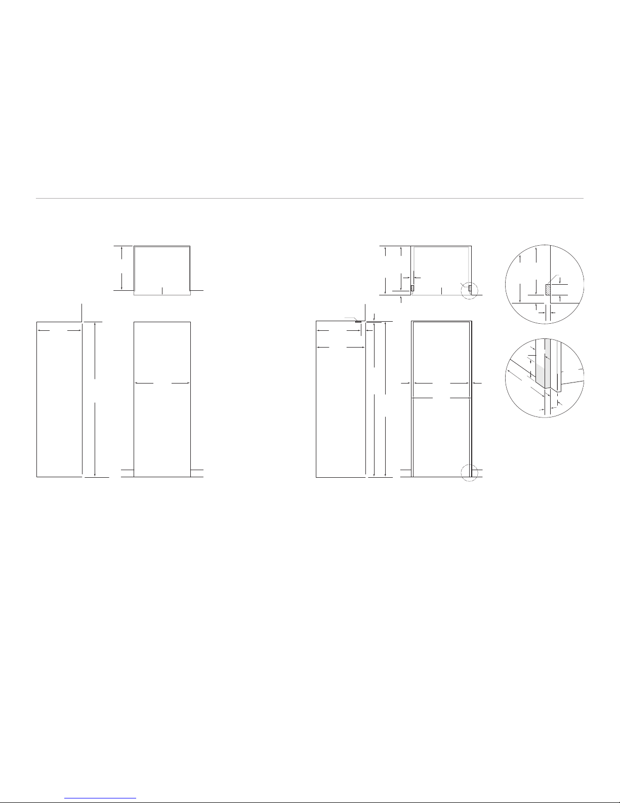
The illustrations above provide a cross section view of the
three panel assembly showing placement of the trim and a
rear view of the three panel assembly with critical dimen-
sions, standard for all models.
Install the handle hardware before inserting the panel. We
recommend a larger D-style pull. The use of a small, one-
piece knob is not recommended. If you use screws with
thick heads, you will need to countersink the screws into
the backer panel before sliding the assembly into place.
Slide the panel into the frame on the door. With the panel
in position, replace the frame end. Be sure the panel is
inserted completely into the channel for proper fit and
alignment.
To reinstall the trim molding, insert the top of the trim
molding into the grooves at the top of the door and work
downward, snapping the trim molding into the clips on the
frame.
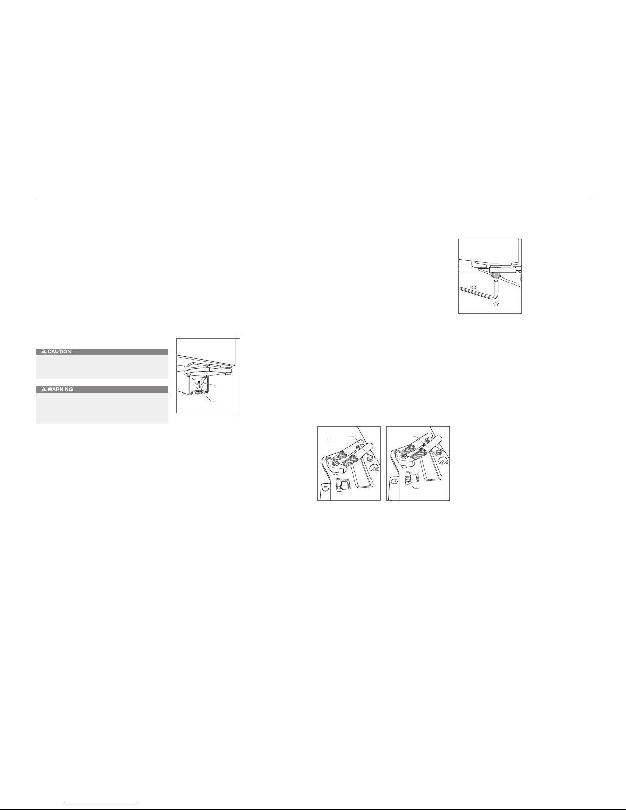
GRILLE PANEL ASSEMBLY
Remove the grille panel assembly as described on page
13. Remove the top two corner screws and pull away the
top frame. Slide the panel into position in the grille frame.
If you are using a grille panel 6 mm or thinner, you will
need to install a filler.
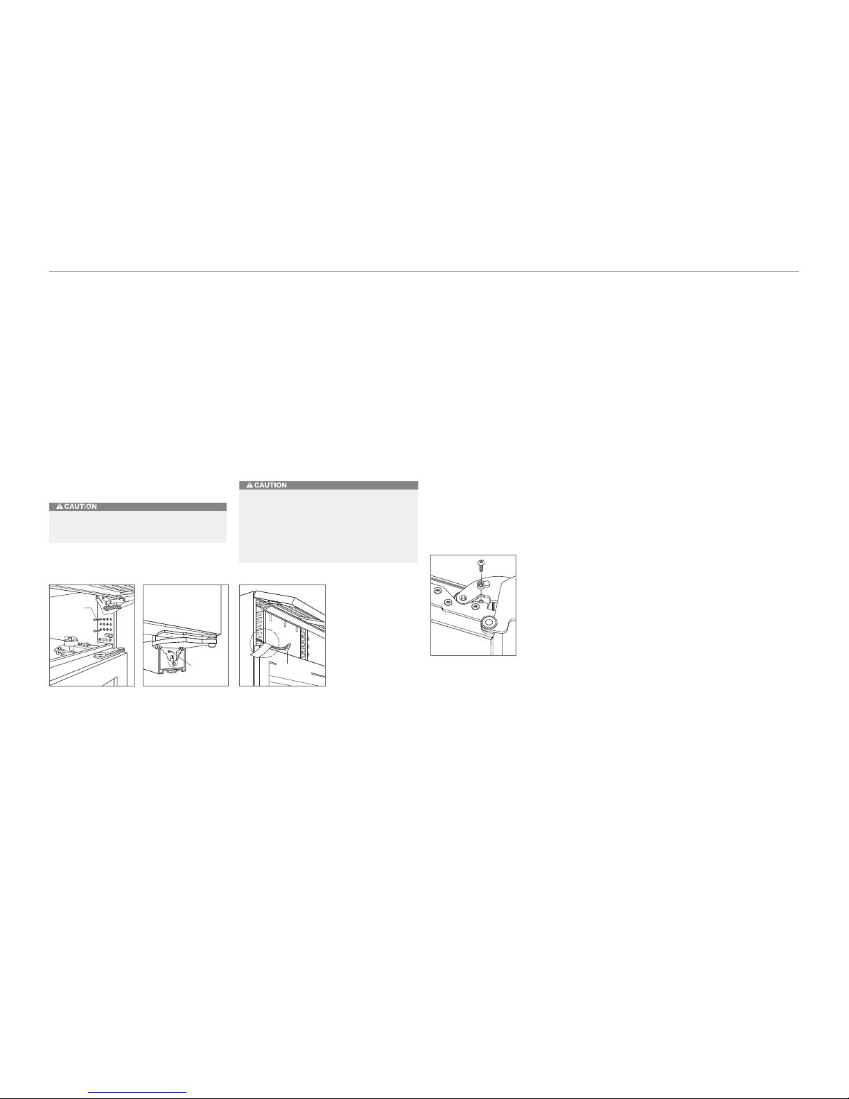
Reattach the top frame by reinstalling the two top corner
screws. Install the grille panel assembly onto the unit,
by reversing the grille removal procedure outlined on
page 13.
Refer to specifications for overlay grille panels and the
illustrations to the left for the exact sizing of all three
panels.
Do not exceed the panel dimensions listed for the
appropriate overlay grille panel you are specifying.
The overlay decorative panel cannot be any larger or
it may restrict the air flow to the compressor area
and cause problems with the operation of the
Sub-Zero unit.
Overlay Panels Specifications
Grille panel dimensions listed are for a standard 2134 mm
overall height of the unit. For a 2108 mm overall height,
subtract 25 mm from grille panel height dimensions. For a
2235 mm overall height, add 102 mm to height dimensions.
Width dimensions do not vary.
A solid panel must not be installed on a glass door
unit, as this may cause moisture to form behind the
panel.
Model ICBWS-30
DOOR W H
Overlay Panel 762 mm 1772 mm
Spacer Panel 740 mm 1751 mm
Backer Panel 756 mm 1767 mm
GRILLE WH
Overlay Panel 762 mm 235 mm
Spacer Panel 740 mm 211 mm
Backer Panel 756 mm 227 mm
WINDOW W H
Cut-Out 597 mm 1607 mm
A
Location 83 mm