10 | Sub-Zero Customer Care 800.222.7820
WOOD FLOOR APPLICATION
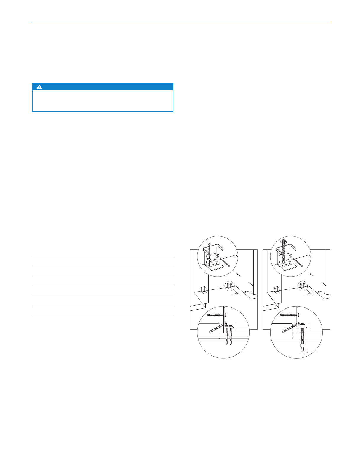
After properly locating the anti-tip brackets in the open-
ing, drill pilot holes ⁄" (5) diameter maximum in the wall
studs or wall plate. Use the #12 screws and washers to
secure the brackets. Verify the screws penetrate through
the flooring material and into the wall studs or wall plate a
minimum of ⁄" (19). Refer to the illustration below.
CONCRETE FLOOR APPLICATION
After properly locating the anti-tip brackets in the opening,
drill pilot holes ⁄" (5) diameter maximum in the wall studs
or wall plate. Drill ⁄" (10) diameter holes into the concrete
a minimum of 1⁄" (38) deep. Use the #12 screws and
washers to secure the brackets to the wall, and use the ⁄"
wedge anchors to secure the brackets to the floor. Verify
the screws penetrate the wall studs or wall plate a mini-
mum of ⁄" (19). Refer to the illustration below.
Anti-Tip Bracket
WARNING
To prevent the unit from tipping forward, the anti-tip
brackets must be installed.
The two anti-tip brackets must be installed exactly 24"
(610) from the front of the opening to the back of the
brackets and a minimum of 4" (102) from the sides of the
opening. This depth will increase to 26⁄" (665) for a flush
inset installation based on ⁄" (19) thick panels. Failure to
properly position the anti-tip brackets will prevent proper
engagement.
Use all anti-tip bracket hardware as instructed for wood or
concrete floors.
IMPORTANT NOTE: For wood or concrete floor applica-
tions, if the #12 screws do not hit a wall stud or wall plate,
use the #8 screws and #12 washers with the wall anchors.
IMPORTANT NOTE: In some installations the subflooring
or finished floor may necessitate angling the screws used
to fasten the anti-tip brackets to the back wall.
ANTI-TIP HARDWARE
2Anti-tip brackets
12 #12 x 2⁄" pan head screws
4⁄"–16 x 3⁄" wedge anchors
12 #12 flat washers
4#8–18 x 1⁄" truss head screws
4Nylon Zip-it® wall anchors
Site Preparation
4" (102)
MIN
24"
(610)
SUBFLOORING
WOOD FLOOR
WALL PLATE
FINISHED
FLOORING
4" (102)
MIN
24"
(610)
SUBFLOORING
CONCRETE
FLOOR
WALL PLATE
FINISHED
FLOORING
11/2"(38)
min
SUBFLOORING
CONCRETE
FLOOR
WALL PLATE
FINISHED
FLOORING
11/2"(38)
MIN
Wood floor
Concrete floor