GB
Operating Instructions
Please keep carefully for future use
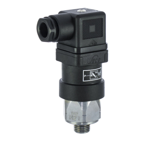
Diaphragm-/
Piston Pressure Switch
with connector
Series 0184
Series 0185
Installation and commissioning must be carried out
in accordance with these Operating Instructions
and by authorized, qualified personnel only.
SUCO Robert Scheuffele GmbH & Co. KG
Keplerstraße 12-14
74321 Bietigheim-Bissingen, Germany
Phone: + 49-7142-597- 0
Fax: + 49-7142-980151
e-Mail: info@suco.de
www.suco.de
Operation and use
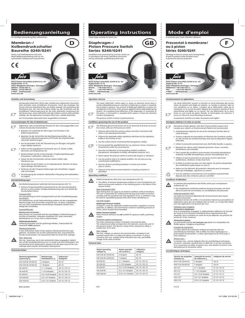
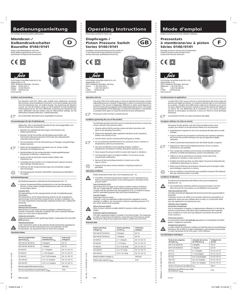
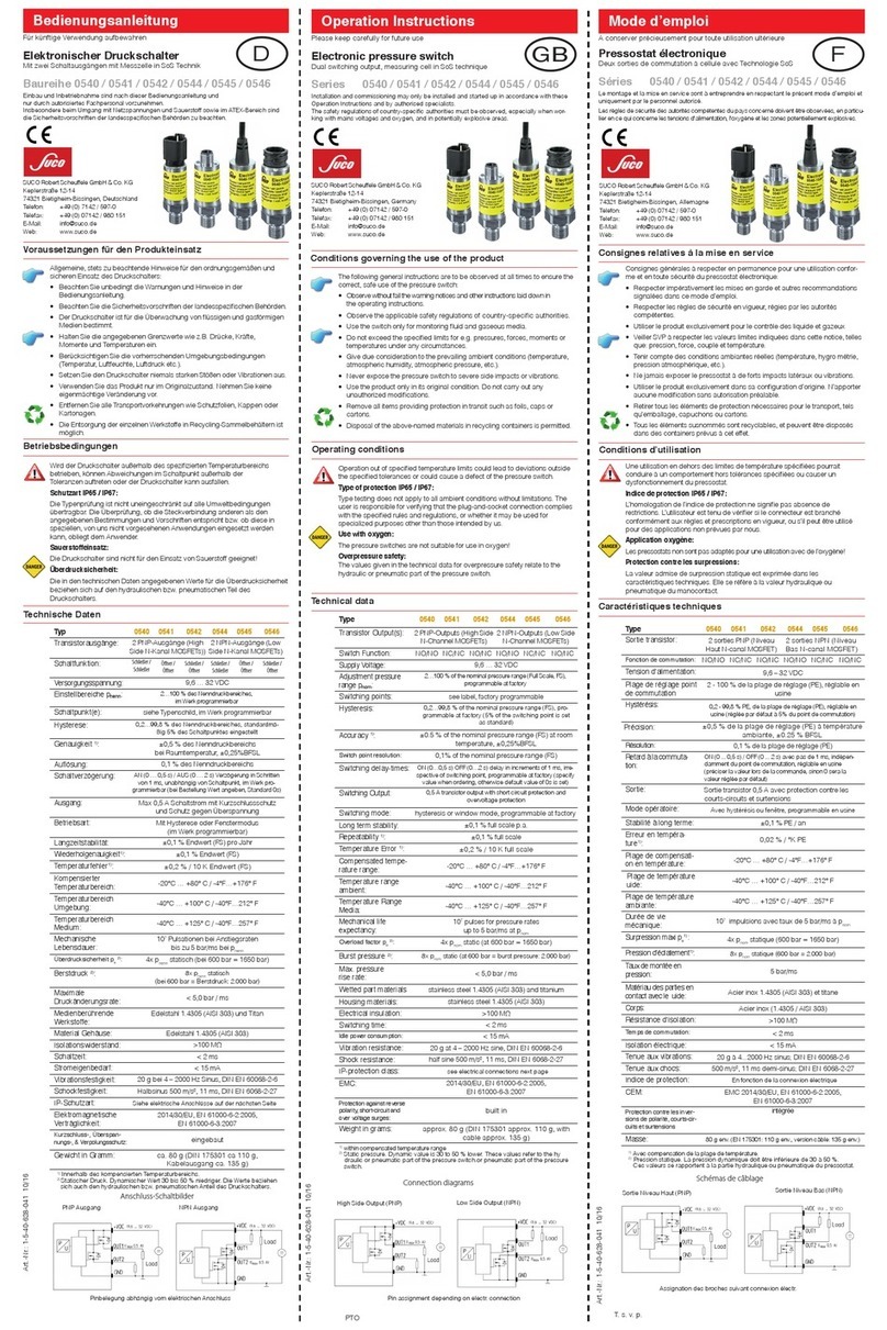
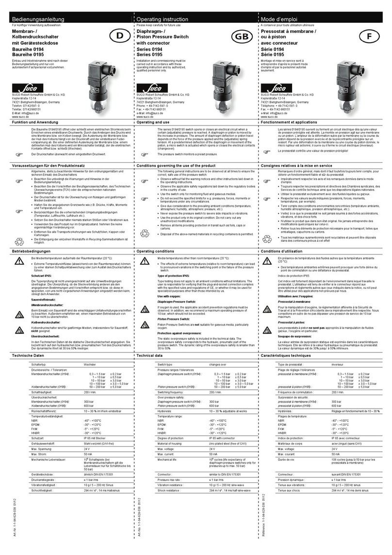
The series 0184/0185 switch opens or closes an electrical circuit when a certain
(adjustable) pressure is reached. A diaphragm or piston is moved by the increase
in pressure. The amount of diaphragm deflection or piston travel depends on
the force of the pressure applied and the (adjustable) spring tension. At a prede -
termined deflection of the diaphragm or movement of the piston, a microswitch
is actuated which opens or closes the electrical contacts (changeover).
The pressure switch monitors a preset pressure.
Conditions governing the use of the product
The following general instructions are to be observed at all times to ensure the
correct, safe use of the pressure switch:
• Observe without fail the warning notices and other instructions laid
down in the operating instructions.
• Observetheapplicablesafetyregulationslaiddownbytheregulatory
bodies in the country of use.
• Use the switch only for monitoring fluid and gaseous medias.
• Donotexceedthespeciedlimitsfore.g.pressures,forces,momentsor
temperatures under any circumstances.
• Give due consideration to the prevailing ambient conditions
(temperature, atmospheric humidity, atmospheric pressure, etc.).
• Never expose the pressure switch to severe side impacts or vibrations.
• Usetheproductonlyinitsoriginalcondition.Donotcarryoutany
unauthorized modifications.
• Remove all items providing protection in transit such as foils,
caps or cartons.
• Disposaloftheabove-namedmaterialsinrecyclingcontainersis
permitted.
Operating conditions
Media temperatures other than room temperature (20 °C):
•The effects of extreme temperatures (relative to room temperature) can
lead to pronounced variations in the switching point or the failure of the
pressure switch.
Type of protection IP65:
Type testing does not apply to all ambient conditions without limitations.
The user is responsible for verifying that the plug-and-socket connection com-
plies with the specified rules and regulations of CE, or whether it may be used
for specialized purposes other than those intended by us.
Use with oxygen:
Diaphragm Pressure Switch:
If oxygen is used, the applicable accident prevention regulations must be
observed. In addition, we recommend a maximum operating pressure of 10
bar, which should not be exceeded.
Piston Pressure Switch:
Piston Pressure Switches are not suitable for gaseous media, particulary
oxygen.
Protection against overpressure:
The static overpressure safety is included in the technical data.
The overpressure safety corresponds to the hydraulic, pneumatic part of the
pressure switch. The dynamic rating of the overpressure safety is smaller than
30 to 50%.
Technical data
Rated operating
voltage Ue
Rated operating
current Ie
Utilization
category
250 Volt AC 50/60 Hz 4 Ampere AC 12
250 Volt AC 50/60 Hz 1 Ampere AC 14
30VoltDC 4 / 4 Ampere DC12/DC13
50VoltDC 2 / 1 Ampere DC12/DC13
75VoltDC 1 / 0.5 Ampere DC12/DC13
125VoltDC 0.3 / 0.2 Ampere DC12/DC13
250VoltDC 0.25 / 0.2 Ampere DC12/DC13
Rated insulation voltage Ui300 Volt
Rated surge capacity Uimp: 2.5 kV
Rated thermal current Ithe: 5 Ampere
Switching overvoltage: < 2.5 kV
Ratedfrequency: DCund50/60Hz
Rated current of short-circuit protective decvice: Up to 5 Ampere
Rated short-circuit current: < 350 Ampere
IP-protection to EN 60 529:1991: IP65 with plug
Tightening torque for terminal screws: < 0.35 Nm
Connection size: 0.5 to 1.5 mm2
Cable screw coupling: Pg 9
ConnectorwithLED: Pg11
Cable size: Pg 9: 6 to 9 mm
Pg 11: 6 to 11 mm
Operating frequency: < 200 min-1
Switching hysteresis: 10 to 30% adjustable
by the factory
Mechanical life 106 operating cycles
Diaphragmtype(0184): (atatrippressuresupto
50 bar)
Piston type (0184): 106operating cycles
Body material: Zinc-plated steel
(Fe//ZnNi(12)6//A/T2)
Temperature range: NBR -30 °C to +100 °C
EPDM -30°Cto+120°C
FKM -5 °C to +120 °C
Overpressure safety
DiaphragmPressureSwitch(0184): 100bar(0.3to1.5bar)
300 bar (restidual pressure)
Piston Pressure Switch (0185): 600 bar
Operating controls and connections
7
max. 0.5 Nm 4
7
P
24
1
(1) Pressure connection
(2) Electrical connection
(3) Adjusting screw
(4) Fastening screw
(5) Plug housing
(6) Gasket
(7) Terminal board
(8) Pg gland
Fig. 3
Fig. 2
Fig. 4
Fig. 1
2
3
3
1
4
58
6
7


