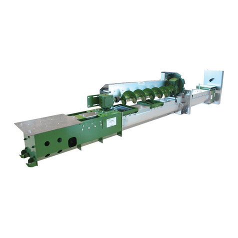
Sukup 5K Commercial Paddle Sweep Quick start guide

5K Commercial Paddle Sweep
Sweeps 4,000 to 6,000 bph
Owner's Installation & Operation Manual
Manual L14359M
06/04/2020 © Sukup Manufacturing Co.
Sukup Manufacturing Co.
1555 255th Street, Box 677
Sheffield, Iowa, USA 50475-0677
Phone: 641-892-4222
Fax: 641-892-4629
Website: www.sukup.com
E-mail: info@sukup.com
DATES REVISIONS PAGES
06/04/2020 – Updated sump switch installation instructions ................................................................................ 31
Updated wear track & parking plate installation instructions ..................................................... 33-34
Updated operating instructions ................................................................................................. 35-36
Updated pusher gearbox lubrication instructions ........................................................................... 43
04/24/2020 – Updated/added center sump dimensions drawings ..................................................................... 9-10
Updated carrier wheel installation instructions .......................................................................... 24-25
Added instructions for pusher carrier wheels assy. installation ..................................................... 27
Updated paddle chain installation instructions ............................................................................... 28
Added instructions for preparing speed reducer for installation ..................................................... 29
Added instructions for installing switch for flush-floor sump .......................................................... 31
Added instructions for installing main power box & control panel .................................................. 31
Added Software Manual ............................................................................................................ 37-41
Updated/added sweep layout drawings .................................................................................... 46-51
Updated wiring diagrams........................................................................................................... 52-61
Updated/added drawings & parts lists ..................................................................... 72-75, 78, 90-91
12/03/2019 – Changed name throughout from Medium Duty Paddle Sweep
Updated sump layout drawings ................................................................................................. 13-15

Table of Contents
2
Table of Contents
Limited Warranty --------------------------------------------------------------------------------------------------- 3
Safety ----------------------------------------------------------------------------------------------------------------- 4
Assembly Instructions -------------------------------------------------------------------------------------------- 8
Operation ------------------------------------------------------------------------------------------------------------ 35
Software Manual --------------------------------------------------------------------------------------------------- 37
Maintenance -------------------------------------------------------------------------------------------------------- 42
Layout Drawings --------------------------------------------------------------------------------------------------- 46
Wiring Diagrams --------------------------------------------------------------------------------------------------- 52
Dodge Speed Reducer manual pages ----------------------------------------------------------------------- 62
Parts Assemblies -------------------------------------------------------------------------------------------------- 72
Contact Information ----------------------------------------------------------------------------------------------- 92
Introduction
This product was carefully designed to give years of dependable service and was manufactured with the
finest materials available. This manual includes information relating to safety, installation and
maintenance, and should be read thoroughly prior to installation. Reliability and service life of this
product depend a great deal on care taken in installation and maintenance.
Receiving and Inspection
Carefully inspect shipment as soon as it is received for any damage. Verify that quantity of parts and/or
packages received corresponds to quantity shown on packing slip. Report any damage or shortage to
delivery carrier as soon as possible. Sukup Manufacturing Co.’s responsibility for damage to equipment
ended with acceptance by delivery carrier. Refer to bill of lading. Save all paperwork and documentation
furnished with the power sweep.
DISCLAIMER: Bin sweeps will vary in performance based on grain condition and condition of bin floor.
Any capacities provided by Sukup Manufacturing Co. are based on dry, clean corn and ideal conditions.

Limited Warranty
3

Safety
4
On safety decals, this symbol and the
signal words Danger, Warning, Caution
and Notice draw your attention to
important instructions regarding safety.
They indicate potential hazards and levels of intensity.
RED - DANGER indicates an
imminently hazardous
situation which, if not avoided, will result in death or
serious injury.
ORANGE - WARNING
indicates a potentially
hazardous situation which, if not avoided, could result
in death or serious injury.
YELLOW - CAUTION
indicates a potentially
hazardous situation which, if not avoided, may result
in minor or moderate injury.
BLUE - NOTICE alerts you to
practices unrelated to personal
injury, such as messages related to property damage.
IMPORTANT: To prevent serious injury or death to
you or your family, it is essential that safety decals
are clearly visible, in good condition, and applied to
the appropriate equipment.
FOLLOW MANUAL & SAFETY DECAL MESSAGES
Carefully read this manual and
all safety decals on your
equipment. Safety decals must
be kept in good condition.
Replace missing or damaged
safety decals by contacting Sukup
Manufacturing Co. via mail at PO
Box 677, Sheffield, Iowa USA, 50475; by phone at
641-892-4222; or by e-mail at info@sukup.com.
It is the responsibility of the owner/operator to know
what specific requirements, precautions, and work
hazards exist. It is also the responsibility of the
owner/operator to inform anyone operating or
working in the area of this equipment of hazards and
safety precautions that need to be taken to avoid
personal injury or death. Always keep children away
from bins and vehicles with flowing grain.
Make no unauthorized modifications to machine.
Modifications may endanger function and/or safety of
unit. Keep unit in good working condition. Keep shields
in place. Replace worn or missing shields free of
charge by contacting Sukup Manufacturing Co.
GRAIN BIN SAFETY
Owners/operators are responsible for developing
site-specific confined space entry procedures.
OSHA’s confined space entry procedures (29CFR
1910.146) can be found at www.osha.gov.
If you must enter bin for repair or maintenance:
Use a safety harness, safety line and respirator
Station another person outside of bin
Avoid the center of the bin
Wear appropriate personal protective equipment
Keep clear of all augers and moving parts
DANGER: Never enter bin unless all power is
locked out and another person is present.
Rotating augers
can kill or
dismember!
NEVER enter bin when augers are running!
When bin is nearly empty, sweep auger will travel at an
increasingly fast speed. Keep away from sweep and
sump augers to avoid entanglement.
Failure to follow precautions above will result in death
or serious injury.
DANGER: Flowing grain
may trap and suffocate. If
you enter a bin of flowing grain
you can be completely submerged
in grain in about 8 seconds.
Failure to heed this warning will
result in death or serious injury.
Read manual before installing or using product. Failure to follow instructions and safety precautions in
manual can result in death or serious injury. Keep manual in a safe location for future reference.

Safety
5
Refer to OSHA 1910.132
(Personal Prot. Equip.)
To avoid electric shock or electrocution, all
equipment must be properly wired and grounded
according to electrical codes. Have unit wired by
qualified electrician.
Have an electrician install a main power disconnect
switch capable of being locked only in OFF position.
Mark disconnect
clearly as to
equipment it
operates.
Always lock out
main power
disconnect
switch whenever
equipment is not
in use.
WARNING: When servicing equipment, never
enter bin unless all power is locked out and
another person is present. Always LOCK OUT all
power and always check with voltage meter before
servicing.
Failure to do so could result in death or serious injury.
Owners/operators are responsible for developing
site-specific Lockout/Tagout procedures based on
equipment at their work site. See OSHA’s typical
minimal lockout procedures (29CFR 1910.147 App A)
at www.osha.gov.
WARNING: KEEP CLEAR OF ALL MOVING
PARTS.
Keep people (ESPECIALLY YOUTH) away from
equipment, particularly during operation.
Keep away from all moving parts.
Keep all shields in place. SHUT
OFF AND LOCK OUT all power
before servicing.
Failure to follow precautions above
could result in death or serious
injury.
WARNING: Metal is slippery when wet. To
avoid falls, never carry items if climbing on
bin. Maintain secure hand and foothold if
climbing on bin. Failure to do so could result in death
or serious injury.
CAUTION: Metal edges are sharp. To avoid
injury, wear protective clothing and handle
equipment and parts with care.
Failure to do so may result in minor or moderate injury.
PERSONAL PROTECTIVE EQUIPMENT
Owners/Operators are
responsible for developing
site-specific personal
protective equipment
standards. OSHA’s
personal protective
equipment standards
(29CFR 1910.132) can be
found at www.osha.gov.
EMERGENCIES – KNOW WHAT TO DO
Have emergency numbers and written directions to
work site readily available in case of emergency. An
area for emergency phone numbers to be recorded is
provided below and at end of this manual.
Ambulance • Fire • Police: 9-1-1
Bin rescue team: _______________________
Emergency medical squad: ______________
Address of work site: ___________________
Directions to work site:__________________

Safety
6
Safety Decals for Bin Sweep
Safety decals should be mounted on your equipment
as shown in this safety section. Yearly and prior to
equipment use, check that all decals and shields are
in place and legible.
To order a replacement decal or shield at no charge,
contact your dealer or Sukup Manufacturing Co., Box
677, Sheffield, IA USA 50475. If replacement is
necessary, make sure location for decal is free from
grease, oil and dirt. Remove backing from decal and
place in proper position.
Decals 1, 2, 3 and 5 are factory-mounted. Additional
copies of decals 1 and 4 are provided and must be
mounted on site.
IMPORTANT: If suggested locations are not clearly
visible, place safety decals in a more suitable area.
Never cover up any existing safety decals.
1. DECAL L0281 – WARNING: To avoid serious
injury or death. Mount this decal on bin sheet
near door handle.
2. DECAL L0271 – DANGER: Shield missing. Do
not operate!
3. DECAL L0284 – WARNING: Keep away from all
moving parts.
4. DECAL L0258A – DANGER: Do not enter this bin!
Keep clear of all augers. Mount this decal on bin
sheet near door handle and near ladder leading to
roof.
5. DECAL L0114 – WARNING: Exposed buckets or
flights may cause serious injury or death.

Safety
7
Decal Placement for 5K Commercial Paddle Sweep
Fig. 1 shows placement of decals for 5K Commercial Paddle Sweep. If decals are missing or illegible,
please order and affix replacements as described on this and previous page.
Fig. 1

Assembly Instructions
8
5K Commercial Paddle Sweeps are for bins up to 105’ in diameter. See Preparation information below
and be sure to lock out power before sweep installation.
Preparation for Installation on Flush Floor
Installation of Sukup 5K Commercial Paddle Sweep requires pre-installation of a center sump if used on
a flush floor. Fabricate sump frame as shown in Fig. 2. Consult bin pad requirements and qualified
engineer for dimensions A through E, which vary with bin size.
L-shaped rebar must by fully welded to angle iron, and angle iron sections must be welded together at
corners as shown in Fig. 2. Drawing at lower right shows upside-down view of center sump and frame.
Fig. 2 – Center sump foundation
Decide on intermediate sump locations, being sure to avoid locations where sweep wheels will travel.

Assembly Instructions
9
Installation
Install center sump by fully welding top lip of sump to sump frame. Plug-weld holes in sump to sump
frame. Cast sump and frame in concrete. Consider conduit exit direction. Leave void in concrete to allow
for conduit. See Figs. 3 and 4.
Fig. 4 shows center sump dimensions.
Fig. 4 – Center sump dimensions
Fig. 3 – Center
sump pivot
16” SQ. OPENING 24” SQ. OPENING

Assembly Instructions
10
See Figs. 5 & 6 for sump bottom flange dimensions and hole patterns depending on sump size.
See Fig. 7 for dimensions after installation of center sump plug detection switch. NOTE: Switch should fit
under ceiling of most service tunnels. If ceiling is too thick, concrete should be notched when formed.
Fig. 5 – Hole Pattern 1
for 16” sump (left) &
24” sump (right)
Fig. 6 – Hole Pattern 2
for 16” sump (left) &
24” sump (right)
Fig. 7 – Dimensions with center sump plug detection switch installed in 16”
sump (left) & 24” sump (center); Drawing at right applies to both sump sizes

Assembly Instructions
11
Install sweep support cross, sump conduits and guards in center sump as shown in Fig. 8.
Prepare drive housing by removing covers, rear brace and pivot tube. See Fig. 9.
If slip ring will be used (for zero-entry operation of sweep), discard slip ring plate. If slip ring will not be
used, leave slip ring covers in place.
SLIP RING
FRONT COVER
Fig. 9 – Preparing drive
housing for installation
CROSS-SECTION VIEW OF SUMP
Fig. 8 – Installing center
sump support cross,
conduits & guards

Assembly Instructions
12
Attach drive unit to center sump as shown in Fig. 10.
Fig. 10 – Attaching drive unit to center sump
Preparation for Installation on Full Floor
Install drag conveyor as shown in Drag Conveyor Assembly and Owner’s Manual, L2502.
Ensure there is at least 53” clearance between bin wall and far end of opener as shown in Fig. 11.
Fig. 11 – Opener clearance from bin wall

Assembly Instructions
13
Find exact center of bin on unload conveyor and mark the spot. See Fig. 12.
Mark centers of intermediate sumps according to applicable layout drawing (below or on following
pages).
Cut conveyor covers as shown in Fig. 12.
Sump Layouts
See Figs. 13-16 for sump layout depending on diameter of bin.
Fig. 13 – Sump layouts for 36’, 42’ & 48’ dia. bins
Fig. 12 – Cutting
sump holes in
conveyor
36’ bin
42’ bin
48’ bin

Assembly Instructions
14
Fig. 14 – Sump layouts for 54’ & 60’ dia. bins
Fig. 15 – Sump layouts for 72’, 75’ & 78’ dia. bins
54’ bin
60’ bin
72’ bin
75’ bin
78’ bin

Assembly Instructions
15
Fig. 16 – Sump layouts for 90’ & 105’ dia. bins
105’
bin
90’ bin

Assembly Instructions
16
Position center sump over conveyor with center hole at exact center of bin. See Fig. 17.
Adjust six (6) supports at bottom of sump to correct height. Staggered holes provide adjustment for level
installation on uneven concrete. See Detail A.
Remove fasteners from four corners of sump. Use slots in corners as guides to drill through conveyor
flanges. Reinstall fasteners to secure sump to conveyor. Ensure conveyor flanges go over sump flanges.
See Detail B.
Secure six bottom sump supports to concrete foundation using concrete anchors.
Fig. 17 – Installing center sump
DETAIL A
DETAIL B

Assembly Instructions
17
Preparing Intermediate Sumps
Remove sump top and two pull rod attachment bolts. See Fig. 18. Remove 3/8” hardware from four
corners of sump. Loosen two pull-rod carriage bolts but do not remove.
Sumps closest to center sump (one on each side) are independent intermediate sumps. To prepare,
remove sump top, rear gate seal and gate. Flip gate over and loosely attach pull rod bracket to underside
of gate as shown in Fig. 19. Reinstall gate seal.
Fig. 18 – Preparing
intermediate sumps
Fig. 19 – Preparing
independent
intermediate sumps

Assembly Instructions
18
Place sumps on conveyor according to applicable layout drawing. See Pages 13-15.
Conveyor covers should go on top of sump flanges as shown in Fig. 20.
Run pull rods through sumps. Connect pull rods end-to-end using coupling shafts provided. Bolts must
be parallel to conveyor to avoid interference. Do not bolt sumps to conveyor yet.
Attach center sump pull rod to sump gate and to pull rod opener.
Ensure all sumps are fully shut.
Using front holes in gates as guides, drill 3/8” holes through pull rods and attach rods to gates using
previously removed bolts. Fig. 21 shows which pull rod serves which sump. Number of intermediate
sumps will vary depending on bin diameter. Center sump is in middle and is served by middle pull rod.
Open gates slightly to expose rear holes in gates. Use them as guides to drill 3/8” holes in rods. Attach
rods to gates using previously removed bolts.
Shut all gates again. At this point sumps can be slid slightly on conveyor. Adjust them as needed so all
gates are fully closed. Using slots in sump corners as guides, drill two holes through each conveyor
flange and attach sumps to conveyor using previously removed hardware. See Fig. 20.
Fig. 20 – Installing
intermediate sumps
Fig. 21 – Pull rod
serving each sump

Assembly Instructions
19
Install a sweep parking stand on each side of center sump. See Fig. 22. Secure each stand to floor with
four concrete anchors.
If sweep will be used with slip-ring for zero-entry operation, install junction box under parking stand on
opposite side of sweep’s parked location. Run electrical conduit to controls outside of bin.
Mark carrier wheel locations on conveyor covers. Locations marked for carrier wheels must have
bridging to support parked sweep. See applicable drawing in Figs. 23-25 for carrier wheel and bridging
locations.
Fig. 22 – Attaching
sweep stands
36’
42’
48’
54’
Fig. 23 – Carrier wheel & floor
bridging locations for 36’, 42’,
48’ & 54’ dia. bins

Assembly Instructions
20
Fig. 24 – Carrier wheel & floor bridging locations for 60’, 72’, 75’ & 78’ dia. bins
Fig. 25 – Carrier wheel & floor bridging locations for 90’ & 105’ dia. bins
SWEP0157
04/16/2019 RTO
60’
72’
75’
78’
90’
105’
Table of contents
Other Sukup Farm Equipment manuals
Popular Farm Equipment manuals by other brands

COSNET
COSNET RTF Assembly sheet

VOSS.farming
VOSS.farming Poultry Kit instruction manual

Raven
Raven RS1 Guidance and Steering Installation Manual

Farmi Forest Corporation
Farmi Forest Corporation CH380HF OPERATION, MAINTENANCE AND SPARE PARTS MANUAL

Sulky
Sulky Semoir Progress P20 Original instructions

Ziegler
Ziegler PKT 452 Original operating instructions