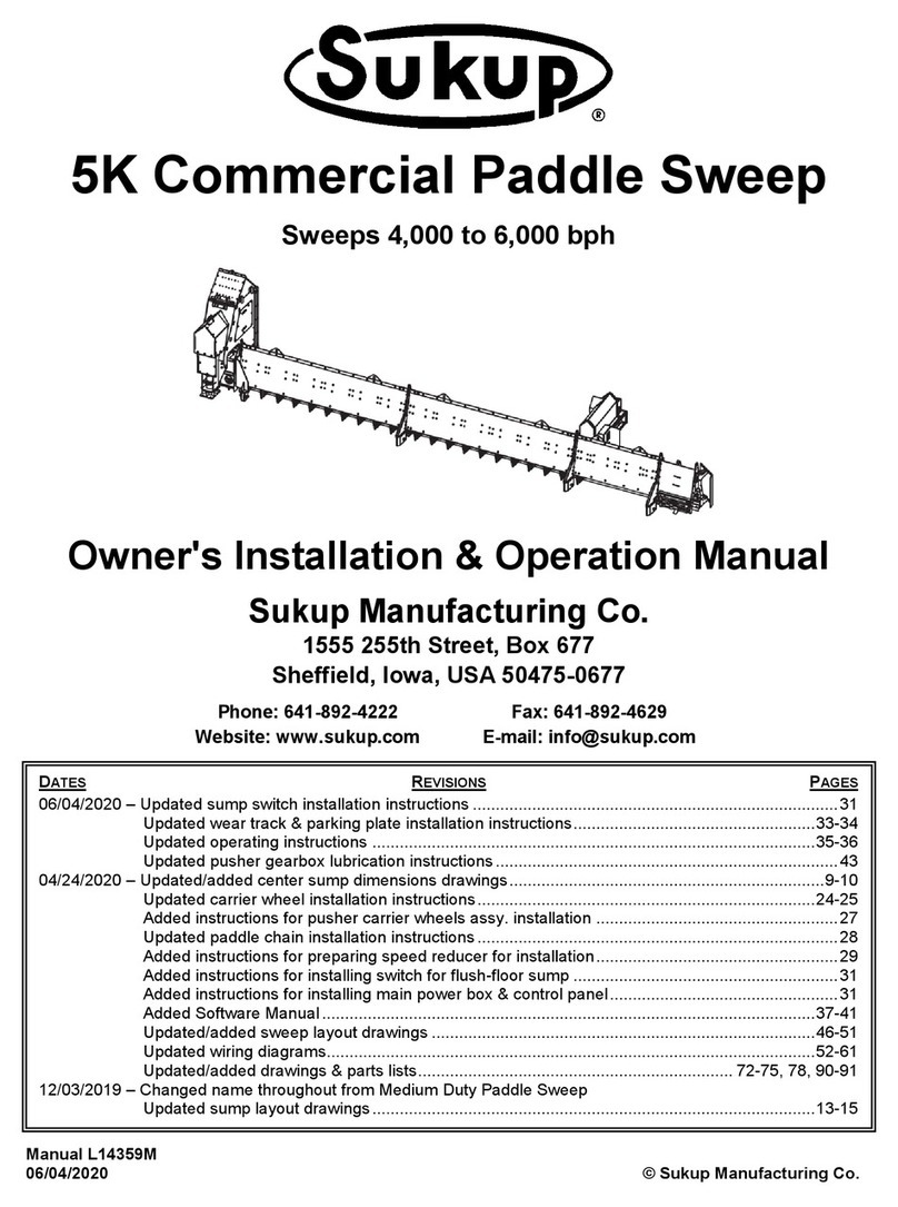
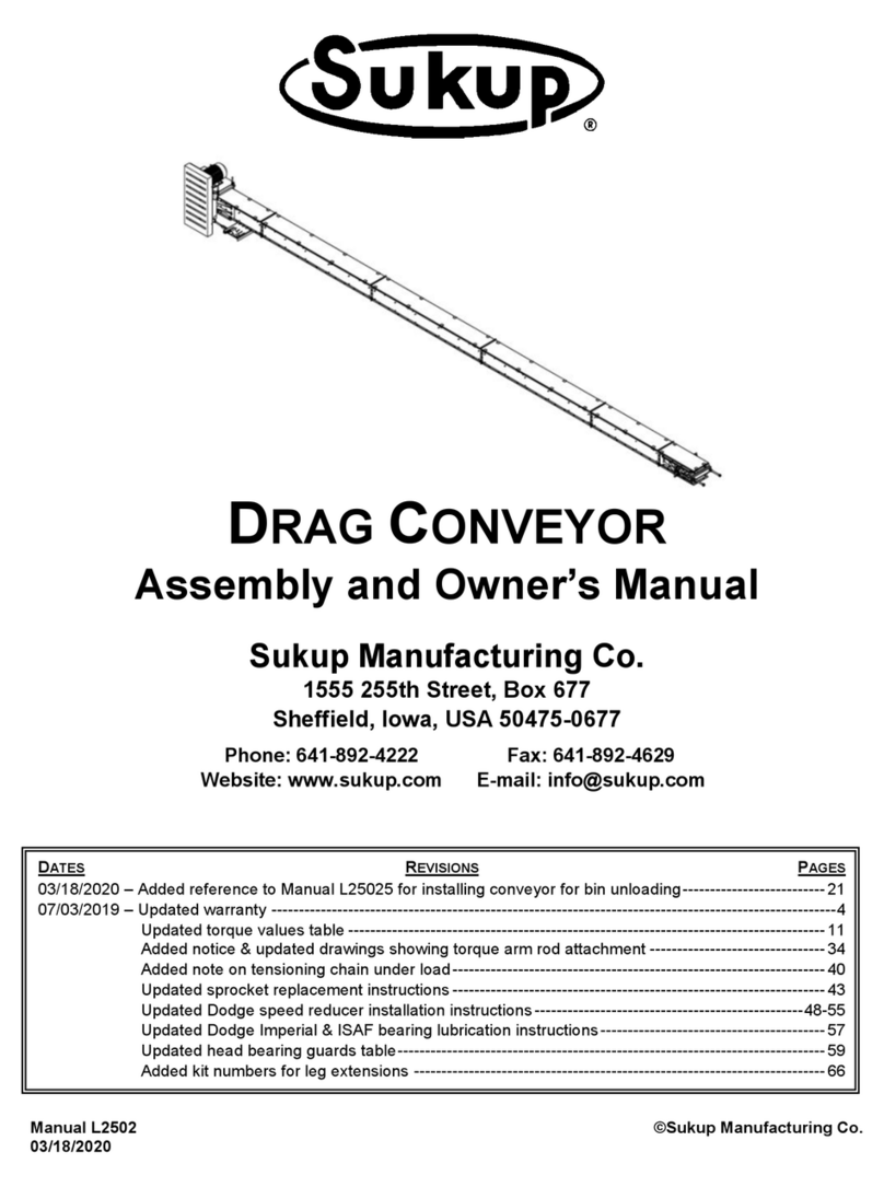
Sukup U-Trough Power Sweep Quick start guide

DATE REVISIONS PAGE
01/31/2020 – Updated bin sweep & scraper installation instructions ..............................................................13-16
Updated Cluster Buster installation instructions ........................................................................22-23
Updated statement on verifying suitability of bin for use with power sweep .................................. 24
Updated &/or added parts/assemblies drawings & parts lists ..................... 26-27, 32, 34-36, 40, 42
U Trough Power Sweep
with
Extended Center Sump
Owner’s Installation & Operation Manual
Manual L143541 ©Sukup Manufacturing Co.
01/31/2020
Sukup Manufacturing Co.
1555 255th Street, Box 677
Sheffield, Iowa, USA 50475-0677
Phone: 641-892-4222
Fax: 641-892-4629
Website: www.sukup.com
E-mail: [email protected]

Introduction / Table of Contents
2
INTRODUCTION
Congratulations on your purchase of the Extended-Sump U Trough Power Sweep. This product was
designed, built and tested to assure highest quality and maximum life.
Read and study operator’s manual carefully to learn how to safely service and operate your machine.
Failure to do so could cause personal injury or equipment damage.
For easy reference, fill in the following information:
Bin diameter: _____
Drive motor hp: _____
Date of U-Trough purchase: _______________________________
DISCLAIMER: Bin sweeps will vary in performance based on grain condition and condition of bin floor.
Any capacities provided by Sukup Manufacturing Co. are based on dry, clean corn and ideal conditions.
It may take two passes over a given area to remove grain, with a layer of grain remaining on floor
afterward.
TABLE OF CONTENTS
Limited Warranty ........................................................................................................................ 3
Safety ......................................................................................................................................... 4
Dimensions ................................................................................................................................ 8
Preparation / Installation ............................................................................................................10
Sweep Installation Instructions ..................................................................................................13
Attaching Sweep Stop ...............................................................................................................15
Powerhead Options ...................................................................................................................17
Adjusting Belt Tension...............................................................................................................21
Cluster Buster Installation .........................................................................................................22
Operating Instructions ...............................................................................................................24
Troubleshooting ........................................................................................................................25
Lubrication ................................................................................................................................25
Parts/Assemblies ......................................................................................................................26
Quick Reference Parts List (Motors, Pulleys, Bushings) ............................................................43
Contact Information ...................................................................................................................44

Limited Warranty
3

Safety
4
On safety decals, this symbol and the
signal words Danger, Warning, Caution
and Notice draw your attention to
important instructions regarding safety.
They indicate potential hazards and levels of intensity.
RED - DANGER indicates an
imminently hazardous
situation which, if not avoided, will result in death or
serious injury.
ORANGE - WARNING
indicates a potentially
hazardous situation which, if not avoided, could result
in death or serious injury.
YELLOW - CAUTION
indicates a potentially
hazardous situation which, if not avoided, may result
in minor or moderate injury.
BLUE - NOTICE alerts you to
practices unrelated to personal
injury, such as messages related to property damage.
IMPORTANT: To prevent serious injury or death to
you or your family, it is essential that safety decals
are clearly visible, in good condition, and applied to
the appropriate equipment.
FOLLOW MANUAL & SAFETY DECAL MESSAGES
Carefully read this manual and
all safety decals on your
equipment. Safety decals must be
kept in good condition. Replace
missing or damaged safety decals
by contacting Sukup
Manufacturing Co. via mail at PO
Box 677, Sheffield, Iowa USA, 50475; by phone at
641-892-4222; or by e-mail at info@sukup.com.
It is the responsibility of the owner/operator to know
what specific requirements, precautions, and work
hazards exist. It is also the responsibility of the
owner/operator to inform anyone operating or
working in the area of this equipment of hazards and
safety precautions that need to be taken to avoid
personal injury or death. Always keep children away
from bins and vehicles with flowing grain.
Make no unauthorized modifications to machine.
Modifications may endanger function and/or safety of
unit. Keep unit in good working condition. Keep shields
in place. Replace worn or missing shields free of
charge by contacting Sukup Manufacturing Co.
GRAIN BIN SAFETY
Owners/operators are responsible for developing
site-specific confined space entry procedures.
OSHA’s confined space entry procedures (29CFR
1910.146) can be found at www.osha.gov.
If you must enter bin for repair or maintenance:
Use a safety harness, safety line and respirator
Station another person outside of bin
Avoid the center of the bin
Wear appropriate personal protective equipment
Keep clear of all augers and moving parts
DANGER: Never enter bin unless all power is
locked out and another person is present.
Rotating augers
can kill or
dismember!
NEVER enter bin when augers are running!
When bin is nearly empty, sweep auger will travel at an
increasingly fast speed. Keep away from sweep and
sump augers to avoid entanglement.
Failure to follow precautions above will result in death
or serious injury.
DANGER: Flowing grain
may trap and suffocate. If
you enter a bin of flowing grain
you can be completely submerged
in grain in about 8 seconds.
Failure to heed this warning will
result in death or serious injury.
Read manual before installing or using product. Failure to follow instructions and safety precautions in
manual can result in death or serious injury. Keep manual in a safe location for future reference.

Safety
5
To avoid electric shock or electrocution, all
equipment must be properly wired and grounded
according to electrical codes. Have unit wired by
qualified electrician.
Have an electrician install a main power disconnect
switch capable of being locked only in OFF position.
Mark disconnect
clearly as to
equipment it
operates.
Always lock out
main power
disconnect
switch whenever
equipment is not
in use.
WARNING: When servicing equipment, never
enter bin unless all power is locked out and
another person is present. Always LOCK OUT
all power and always check with voltage meter before
servicing.
Failure to do so could result in death or serious injury.
Owners/operators are responsible for developing
site-specific Lockout/Tagout procedures based on
equipment at their work site. See OSHA’s typical
minimal lockout procedures (29CFR 1910.147 App A)
at www.osha.gov.
WARNING: KEEP CLEAR OF ALL MOVING
PARTS.
Keep people (ESPECIALLY YOUTH) away from
equipment, particularly during operation.
Keep away from all moving parts.
Keep all shields in place. SHUT
OFF AND LOCK OUT all power
before servicing.
Failure to follow precautions above
could result in death or serious
injury.
WARNING: Metal is slippery when wet. To
avoid falls, never carry items if climbing on
bin. Maintain secure hand and foothold if climbing on
bin. Failure to do so could result in death or serious
injury.
CAUTION: Metal edges are sharp. To avoid
injury, wear protective clothing and handle
equipment and parts with care.
Failure to do so may result in minor or moderate injury.
PERSONAL PROTECTIVE EQUIPMENT
Owners/Operators are
responsible for developing
site-specific personal
protective equipment
standards. OSHA’s
personal protective
equipment standards
(29CFR 1910.132) can be
found at www.osha.gov.
EMERGENCIES – KNOW WHAT TO DO
Have emergency numbers and written directions to
work site readily available in case of emergency. An
area for emergency phone numbers to be recorded is
provided below and at the end of this manual.
Ambulance • Fire • Police: 9-1-1
Bin rescue team: _______________________
Emergency medical squad: ______________
Address of work site: ___________________
Directions to work site:__________________
Refer to OSHA 1910.132
(Personal Prot. Equip.)

Safety
6
Safety Decals for U-Trough Power Sweep
Safety decals should be mounted on your equipment
as shown in this safety section. Yearly and prior to
equipment use, check that all decals and shields are
in place and legible.
To order a replacement decal or shield at no charge,
contact your dealer or Sukup Manufacturing Co., Box
677, Sheffield, IA USA 50475. If replacement is
necessary, make sure location for decal is free from
grease, oil and dirt. Remove backing from decal and
place in proper position.
Decals 1-6 are factory-mounted. Additional copies of
decals 1 and 4 are shipped with this manual in
separate packet #A3399 and have mounting
instructions inside packet.
IMPORTANT: If suggested locations are not clearly
visible, place safety decals in a more suitable area.
Never cover up any existing safety decals.
1. DECAL L0281 – WARNING: To avoid serious
injury or death. Mount this decal on bin sheet
near door handle.
2. DECAL L0271 - DANGER: Shield missing. Do not
operate!
3. DECAL L0284 – WARNING: Keep away from all
moving parts.
4. DECAL L0258A – DANGER: Do not enter this
bin! Keep clear of all augers. Mount this decal on
bin sheet near door handle and near ladder
leading to roof.
5. DECAL L03061 – DANGER: Keep away when
auger is running!
6. L03287 – Instructional sticker for U-Trough Power
Sweep. For placement, see drawing on next page.

Safety
7
Decal Placement for U-Trough Power Sweep
Fig. 1 shows placement of safety decals and instructional sticker for U-Trough Power Sweep with
extended center sump.
Fig. 1

Dimensions
8
DIMENSIONS
See Fig. 2 for dimensions of U-Trough Power Sweep with extended center sump.
See Fig. 3 and Table 1 for dimensions of horizontal powerhead.
Fig. 3 & Table 1 – Powerhead dimensions
IMPORTANT: Dimensions are based on nominal bin diameters listed and provide approximate
measurements (+ or - 1”) for planning and layout purposes.
POWERHEAD
DIMENSIONS
BIN DIA.
A
B
C
D
E
F
24
192
200
72
57
49
12
27
210
218
72
57
49
12
30
228
236
72
57
49
12
33
246
254
72
57
49
12
36
264
272
72
57
49
12
42
300
308
72
57
49
12
48
336
344
72
58
50
13
54
372
380
73
58
50
13
60
408
416
73
58
50
13
Fig. 2

Dimensions
9
See Fig. 4 for dimensions of 20° incline powerhead.
Fig. 4 – 20° incline powerhead dimensions

Preparation / Installation
10
PREPARATION / INSTALLATION
U-Trough is designed to be installed under a steel aeration floor, but may be installed in a bin with a
concrete floor and trench as shown in Fig. 5. Instructions are provided for both types of floor. In either
case, the first step is to determine from which side of bin grain will be unloaded.
U-Trough must have unobstructed path to center sump, and center of top gearbox must be in exact
center of bin as shown in Fig. 5. Locate center of bin by taking several measurements.
For installation in concrete trench:
Ensure trench meets dimensions shown in Fig. 5. Trench must be formed when foundation is poured.
Use a cut-off wheel to remove rear tabs as shown in Fig. 5 to allow flush fit between concrete and center
sump.
Position U-Trough as shown in Fig. 5 so top of gearbox is at exact center.
IMPORTANT: Ensure U-Trough is level and parallel with top of floor. Use shims if needed.
A two-piece metal plate may need to be field-fabricated and placed around U-Trough for attachment of
bin collar. Plate will be located inside of bin collar and attached to foundation and bin wall.
For installation in full aeration floor:
NOTE: If installing in existing bin with a full aeration floor, it may be necessary to remove about half of floor.
Before installation, check floor height:
Minimum plenum height required for installation of U-Trough is 13-1/4".
Maximum floor thickness is 1-3/4".
Fig. 5

Installation
11
Fig. 8 – Bin collar sections
mounted to bin & U-Trough
Fig. 7 – Removing top gearbox
Align center of bin collar with a flashing bolt above desired unloading location. See Fig. 6. Use collar’s
eight 1/4" holes to mark sidewall sheet. Remove collar and draw straight lines between markings. Cut
hole in bin sheet using lines and radius markings. Cutout should be no larger than needed.
If floor has not previously been installed, install half of bin floor on side opposite of unload, minus 12
planks closest to center of bin. NOTE: Floor planks must run perpendicular to U-Trough.
For installation in both floor types:
Bring U-Trough into bin, gearbox-
end first. Slide powerhead end
out of bin and position top
gearbox in exact center of bin.
NOTE: If bin does not have a
walk-through door, top gearbox
must be removed and U-Trough
must be slid in through hole in
bin wall. To remove top
gearbox, remove rear
compartment cover and chain
cover. See Fig. 7. Loosen
gearbox support nuts and chain
tensioning nut. Remove four
mounting plate bolts. Push
gearbox back, then pull up to
remove. Once trough is inside of
bin, reinstall top gearbox and
position in exact center of bin.
Position upper and lower sections
of bin collar around U-Trough as
shown in Fig. 8 and use as
templates for drilling bolt holes.
Ensure bolt holes are on “hills” of
bin sheet; field-drill new holes in
collar pieces if needed. Apply
caulk as needed, then attach
upper collar to bin using 3/8”
hardware provided in parts sacks
BL59791 and BL5969. Secure
lower section of bin collar to upper
using 3/8” self-drilling screws.
Fig. 5
Fig. 6

Installation
12
Complete installation of bin floor. See flooring installation manual.
Install floor flashing. Sweep moves clockwise. Ensure that flashing is overlaid so sweep wheel “steps
up.”
Fig. 9
Install sump flanges as shown in Fig. 10. Fasten to floor with self-drilling screws.
Fig. 10

Installation
13
SWEEP INSTALLATION
Start by attaching sweep input shaft to top gearbox. Insert 1/4" key into shaft and insert shaft 1” into
sprocket. See Fig. 11. Tighten two (2) setscrews.
Line up 1” diameter holes in backboard with holes in backboard mount. See Fig. 12. Insert pin and
secure it with two (2) 5/16” bolts, one on each end.
Attach backboard to top gearbox as shown in Fig. 13 using previously installed backboard mount
bracket. Slide a 1-1/8” spacer over each stud protruding from gearbox, then slide studs through
backboard mount bracket. Slide a flat washer over each stud and then a lock washer. Secure with 7/16”
nut on each bolt.
Fig. 11
Fig. 12
Fig. 13

Installation
14
Fig. 14
Fig. 15
Fig. 16
RECLAIM SHIELD
See drawings below for attachment of 17” drive wheel. Slide gearbox assembly shaft into auger as
shown in Fig. 14. Secure with 3/8 x 2-1/4” bolts and 3/8” lock nuts. NOTICE: Ensure gearbox is straight.
Failure to do so may cause auger tube to break.
Bolt gearbox assembly to
backboard using 3/8 x 1” bolts, flat
washers and flange nuts. See Fig.
14.
Remove 5/8” bolt from gearbox
output shaft. Use it to attach drive
wheel as shown in Fig. 15.
Attach grain reclaim shield as
shown in Fig. 15 using 3/8 x 3/4”
bolts, flat washers.
Attach extension plate, support
bracket and stiffener bracket as
shown in Fig. 16 using 3/8 x 3/4”
bolts, flat washers.
NOTE: On reclaim shield there are
three holes in each of the three
sets of holes for mounting
extension plate. Use the middle
hole in each set.
NOTE: If bin has a stirring
machine, trim its down-augers to
avoid contact with sweep and 17”
wheel. Minimum clearance from
any object is 6”.
Attach rear carrier wheel(s) to backboard as shown on Page 40. In bins 35’ dia. and larger, attach one
wheel about 3’ from center of bin and one about 3’ from drive wheel. In smaller bins, attach a single
wheel near middle of backboard. Ensure sumps will be missed by carrier wheel(s). Use orange
stickers on backboard as a guide.

Installation
15
ATTACHING SWEEP STOP
Bolt sweep stop (E5514) to bin wall near door so it can be positioned without entering bin. Bottom of stop
must be 1-1/2” from floor. Mount stop bracket to wall with four (4) 5/16 bolts w/ polyurethane washers,
5/16” fender washers and 5/16” flange nuts. NOTE: Flashing bolts can be used to mount bottom of
bracket. Holes for top of bracket will have to be field-drilled.
Add sweep stop extension (E5515) as shown in Image 1 using two (2) 5/16” bolts and 5/16” flange nuts.
Image 2 shows sweep stop retracted to let sweep pass.
BACKBOARD SCRAPER INSTALLATION
1. Attach scrapers to backboard using 3/8 x 1” carriage bolts, with heads of bolts on auger side of
backboard. See Fig. 17. Place scraper’s short side flat against backboard as shown and align
scraper holes with slots. See Fig. 18. Adjust scraper sections so bottoms are just below auger as
shown in Fig. 17. Tighten 3/8” flange nuts. NOTE: Setting scraper too low will limit forward travel of
sweep auger and reduce unload capacity.
Image 2 – Sweep stop retracted
SWEEP STOP
EXTENSION
(E5515)
Image 1 – Sweep stop extension added for
use with 17” drive wheel
STANDARD SWEEP STOP
(E5514) FOR 10” WHEEL)
Fig. 17

Installation
16
2. Continue attaching scraper sections on backboard until all are installed or until all visible slots in
backboard have been filled. Scraper closest to center sump may only be 18" long depending on bin
diameter. If an 18” section is used, it must be field-attached to inside end of backboard. All scraper
sections provided may not be used. NOTE: If an 18” section of scraper is needed, it will be factory-
attached to back of backboard. Remove and attach to front as directed.
3. Once all scrapers and all other equipment for bin have been installed, exit bin and engage sweep
auger. Start unload system and allow sweep to make one complete revolution in bin to make sure
there is nothing on floor that will catch on scrapers.
DANGER: KEEP AWAY when auger is running. Entanglement with rotating auger will
cause death or serious injury.
4. If scrapers catch on anything, stop unload system and remove obstacle. If it cannot be removed,
raise scraper section that was hitting obstacle until it clears. Back up sweep a couple feet, exit bin
and resume test.
5. Once scrapers are adjusted so sweep can make its revolution in bin freely, shut power off and make
sure scrapers sections are tight. Once bin has been filled, floor and sweep may flex due to weight of
grain. It may be necessary to adjust scrapers again. Make sure sweep auger is positioned just behind
intermediate sumps.
Fig. 18
NOTE: SCRAPERS HAVE TWO SETS OF HOLES.
ATTACH EACH SCRAPER USING HOLES THAT
PROVIDE DESIRED CLEARANCE FROM FLOOR.
ALIGN SCRAPER
HOLES WITH SLOTS
IN BACKBOARD.

Installation
17
Fig. 19 & Table 2
POWERHEAD OPTIONS
Horizontal
1. Remove outer safety shield section from powerhead assembly. Slide lock collar onto auger shaft.
Slide powerhead over flighting so unload auger shaft protrudes through flange bearing. Slide
powerhead on completely so flanges butt against each other.
2. Remove discharge cover and attach powerhead to unload trough using three 1/2 x 1-1/4" screws on
each side flange. See Fig. 19 and Table 2.
3. IMPORTANT: Slide locking collar over auger shaft protruding from powerhead and lock onto flange
bearing. Tighten setscrew on locking collar. Tighten inner collar installed in Step 1.
4. Remove knockout in inner shield for 15-20hp motors.
5. Mount motor to motor mount plate. Use 1/2 x 1-3/4” bolts, nuts, lock washers and flat washers (in
parts sack) for 15-20hp motors. Use 3/8 x 1-3/4" bolts, nuts, lock washers and flat washers for
smaller motors.
6. Mount motor pulley onto motor shaft. Secure with key and setscrew, or with bushing if so equipped.
7. Attach large pulley to shaft extending from powerhead. Place 1/4" key in slot on pulley and align with
keyway in unload shaft. Align pulleys and tighten setscrews on large pulley.
8. Place belts on pulleys. Adjust tension by turning bolt on bottom of motor mount. See Fig. 23 for
proper adjustment of belt tension.
9. Place outer safety shield over pulley and tighten bolts. KEEP SHIELD IN PLACE AT ALL TIMES!
10. Reinstall discharge cover.
*See table on Page 43 for 3-1/2”
pulley, depending on motor shaft dia.
REF. #
DESCRIPTION
QTY.
PART #
1
Key, 1/4" sq. x 2-1/2”
1
E5720
2
Lock collar, 1-1/4”
2
J0068
3
Belt, BX60
3
J0223
4
Belt, BX58
2
J02361
5
Pulley, 3-1/2” OD, 1-3/8” ID, double grv.
1
*
6
Pulley, 3.4”, 3B34SH
1
J0332
7
Pulley, 13.6”, 3B136SK
1
J0389
8
Pulley, 14” OD, 1-1/4” ID, double grv.
1
J03951
9
Bushing, 1-1/4” ID, SK114
1
J0410
10
Bushing, 1-5/8”, SH158
1
J04242
11
Screw, 1/2 – 13 x 1-1/4”
6
J0728
12
Flange nut, 1/2" – 13
6
J10401

Installation
18
Incline
1. Remove shaft from end of unload auger. NOTE: Keep fasteners. They will be used later.
2. Remove cover as shown in Fig. 20 to allow access to incline input shaft.
3. Slide incline up to U-Trough and guide input shaft into unload auger. Provide temporary support.
4. Connect incline to trough using 1/2 - 13 x 1-1/4” bolts as shown in Fig. 20.
5. Secure incline shaft to auger using previously removed bolts. Reinstall cover.
Fig. 20 – Attaching incline to U-Trough

Installation
19
6. Remove bolts from vertical seams of grain bin sidewall panels at bottom of third ring from foundation.
Use bolts to attach brackets as shown in Fig. 21, using the same holes from which bolts were
removed.
7. Loop chains through holes in upper and lower ends of incline as shown in Fig. 21 and secure each
chain using 5/16 x 2” bolt, flat washers and nylon lock nut as shown. Use 5/16 x 1-1/2” bolt, flat
washers and nylon lock nuts to attach other ends of chains to brackets. Use turnbuckles to tighten
chains to fully support incline.
Fig. 21 – Attaching chains to incline
8. Remove outer section of belt shield. Install motor. Use 1/2 x 1-3/4” bolts, nuts, lock washers and flat
washers (in parts sack) for 15-20hp motors. Use 3/8 x 1-3/4" bolts, nuts, lock washers and flat
washers for smaller motors.
9. Attach 14” triple-groove pulley to power shaft using key and bushing. See Table 3.
10. Attach small pulley to motor and align with bottom pulley using straight edge. Install three belts.
Adjust tension by turning bolt on bottom of motor mount. See Fig. 23 to properly tension belts.
11. Reinstall outer belt shield.
≤10HP
15-20HP
PART #
QTY.
PART #
QTY.
Bushing
J04310
1
J04310
1
Pulley
J03952
1
J0389
1
Belts
J0223
2
J02433
3
Table 3

Installation
20
U-TROUGH EXTENSION
See Fig. 22 and instructions below to extend U-Trough. Extension will require increased horsepower.
Do not use with an incline powerhead.
Fig. 22
1. Remove drive shaft from outer section of unload auger.
2. Attach drive shaft to extension auger using same hardware.
3. Align ends of flighting as shown in Fig. 22 and attach using shaft and hardware provided.
4. Connect trough extension to unload trough using 1/2” hardware provided.
5. Support extension as shown in Fig. 22. Ensure supports attach to solid surface and that weight of
trough is evenly distributed. Chains may be used to support end of extension nearest to bin wall.
See Fig. 21 and Step 6 on previous page for attachment of brackets to bin sidewall. Loop chains
through holes in near end of extension and secure each chain using a 5/16 x 2” bolt, flat washers
and nylon lock nut as shown. Use 5/16 x 1-1/2” bolts, flat washers and nylon lock nuts to attach
chains to brackets on bin. Use turnbuckles to tighten chains.
6. Install powerhead.
CHAIN
SUPPORT
LOCATIONS
Table of contents
Other Sukup Farm Equipment manuals