Sullair SAR 003 User manual

MODELS:- SAR 003 TO SAR 175
DESICCANT DRYERS
MAINTENANCE MANUAL
DATE : 24Mar2000 REV: 1

Page 2 of 30
FOREWORD
The compressed air dryer systems have been designed and manufactured to ensure that maximum
safety and performance is achieved. It is expected that users of these systems will employ safe
working practices and ensure that when installing, commissioning, operating or maintaining the
equipment, any legal requirements are fulfilled. For example, in the UK, users should refer to the
Health and Safety Act, 1974.
All ancillary equipment such as pipework, valves, fittings etc., must be suitable for the pressures and
capacities involved.
Replacement parts are available from your distributor or the manufacturers ( see back page for
information). The adoption of a regular servicing policy is strongly recommended and will result in
ensuring that a high performance is achieved. Serial numbers and customer order numbers should
be referred to in any communication. (Serial numbers can be found on the identification plate
attached to the dryer). The figure number and the appropriate diagram in this manual and the item
number (shown in circle,) will also assist in part identification.
Any warranty will be invalidated if the dryer is not installed in accordance with the manufacturers
recommendations or non-approved parts substituted. Substitute parts could reduce the performance
or service life in addition to creating potential hazards.
The manufacturers reserve the right to modify the contents of this manual without notice. The data
given is a guideline to users and in no way binding on the manufacturers.
BEFORE SERVICING OR DISMANTLING ALL PRESSURE MUST BE RELEASED
FROM THE SYSTEM AND ITS ASSOCIATED PIPEWORK AND ANY ELECTRICAL
SUPPLY ISOLATED.

Page 3 of 30
RECOMMENDED ROUTINE MAINTENANCE
Weekly
1. Ensure drain function / operation on all filters.
2. Ensure the change-over occures approximately every 2 mins.
3. Check all gaskets, control valves, pipes and fittings for air leaks.
4. Ensure moisture indicator paper is blue.
Inlet / Outlet elements should be changed every 6000 / 8000 hrs.

Page 4 of 30
Section
A1
A2
A3
A4
A5
A6
Description
Outlet Head Assembly.
Column Assembly.
Inlet Head Assembly.
Cam-Timer Replacement.
Fault Finding Guide.
Piping Schematic Diagrams.
Page No

Page 5 of 30
SECTION A1
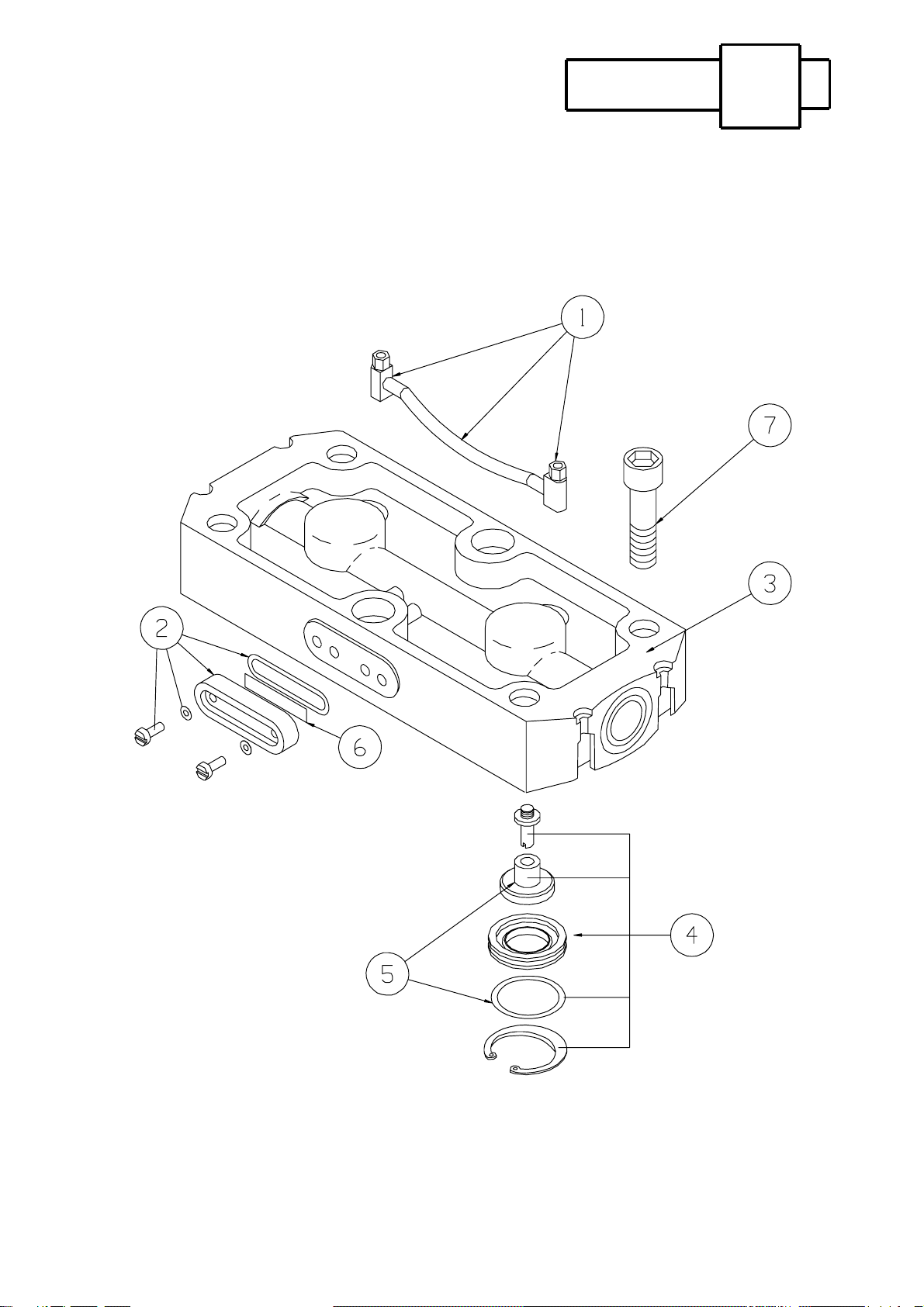
OUTLET HEAD ASSEMBLY
A1.1
A1.2
A1.3
A1.4
Upper Gasket Replacement
Moisture Indicator Removal
Check Valve Replacement
Adjustment of variable purge

OUTLET HEAD ASSEMBLY SECTION A1
A1.1 UPPER GASKET REPLACEMENT
Disconnect outlet pipework. Remove head bolts, lift head clear.
A1.2 MOISTURE INDICATOR REMOVAL
Remove two screws from sight glass. Change indicator paper and refit, ensuring gasket is in
good condition and the air holes are clear.
A1.3 CHECK VALVE REPLACEMENT
Remove outlet head as above. Remove circlip and valve seat with o-ring. Remove check
valve.
SAR065 - SAR 088
Check the valve is accesible when the head and purge plate are removed. Valve discs can be
changed by securing the valve stem and removing the retaining nut. Valve guides can be
removed by unscrewing from the head.
For re-assembly, follow the reverse procedure always fitting new gaskets.
TORQUE HEAD BOLTS TO 25lbf ft
TORQUE SEQUENCE
Page 6 of 30

OUTLET HEAD ASSEMBLY SECTION A1
GENERAL
A1.4 ADJUSTMENT OF VARIABLE PURGE
The variable purge needle valves are situated in the top or rear of the outlet head on the dryer.
NOTE:
The dryer purge needle valves are factory set for 20% of rated flow of the dryer at 7
barg (102 psig) inlet pressure (18% actual @ 6 barg) The purge needle valves only
require adjustment if the inlet pressure to the dryer is not 7 bar g (102 psig).
TO ADJUST THE PURGE
A.
B.
C.
D.
E.
F.
G.
H.
Turn both valve adjusting screws clockwise until they are fully closed .
DO NOT OVER TIGHTEN THESE SCREWS.
The 4mm or 6mm plastic pipe which connects both valves together should be removed
from the push in connections on the valves by pressing on the face of the connection to
release the collet.
A flow meter (not supplied) which is capable of measuring the amount of purge air
required should be fitted to either one of the purge needle valves.
Allow the column, on which the purge needle valve functions to pressurise. Turn the
adjusting screw in an anticlockwise direction until the desired purge flow setting is
obtained. If the flow meter does not register after THREE TURNS, the adjacent
column is pressurising, wait for the desired column to pressurise and continue.
The operating pressure must be maintained throughout in order for the purge flow
setting to be correct.
When the above operation is complete and the correct purge flow is obtained, wait until
the adjacent column pressurises. Remove the flow meter from the previously adjusted
valve and attach to the unadjusted valve. Turn the adjusting screw anticlockwise until
the desired purge flow setting is obtained.
After adjustment has been carried out, remove the flow meter from the previously
adjusted valve. Replace the 4mm or 6mm plastic pipe. A proportionate amount of
purge air will exhaust when this pipe is being fitted, relative to the capacity of the
dryer.
The correctly adjusted unit is now ready for use. For settings other than 7 bar g, consult
the manufacturer.
NOTE: The maximum rated capacity of the flow meter as recommended by the
manufacturers instructions should be checked before use.
Page 7 of 30

OUTLET HEAD ASSEMBLY SECTION A1
PURGE FLOW
Page 8 of 30
SAR 5 - 10 bar CFM 5 - 10 bar L/M
003
006
013
024
065
088
106
129
175
4.8
6.4
8.4
10.6
12.99
17.58
21.2
26.0
35.1
136
181
238
300
368
498
600
736
996

OUTLET HEAD ASSEMBLY SECTION A1
SAR003 to SAR 013 OUTLET HEAD
Page 9 of 30
OUTLET HEAD ASSEMBLY SECTION A1
OUTLET HEAD SAR 024 to SAR 088
Page 10 of 30

OUTLET HEAD ASSEMBLY SECTION A1
SAR 106 to SAR 175
DUPLEX OUTLET HEAD
Page 11 of 30
Page 12 of 30
SECTION A2
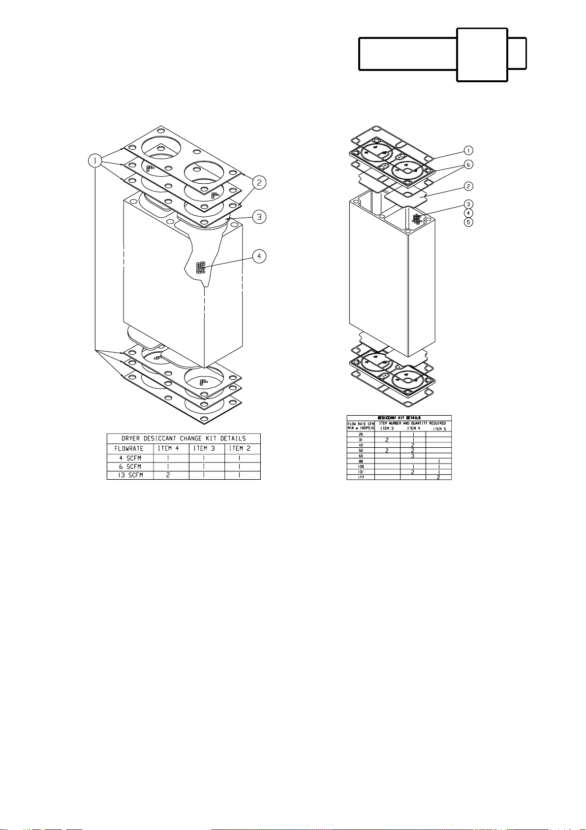
COLUMN ASSEMBLY
A2.1
A2.2
A2.3
Column/Desiccant Removal
Desiccant Replacement
General
COLUMN ASSEMBLIES SECTION A2
SAR 003 TO SAR 013 SAR 024 TO SAR 088
A2.1 COLUMN / DESICCANT REMOVAL
Remove outlet head assembly and upper gasket. Remove upper column pads and remove
desiccant by either inverting dryer or by means of an industrial vacuum cleaner. The bottom
column bolts can be removed and the column lifted clear although complete removal of the
column is not always necessary.
NOTE : DESICCANT IS NOT REUSEABLE AND MUST BE DISCARDED.
A2.2 DESICCANT REPLACEMENT
Ensure the columns are free from dust, fit new lower column pads and check lower gasket is in
good condition. Refilling can now take place. In order to maintain dryer performance, the
columns must be refilled using a snowstorm filling device which will achieve maximum
packing density. The best results are obtained by using a smooth continuous operation.
A2.3 GENERAL
Each extrusion consists of 2 chambers filled with desiccant material. The manufacturer
suggests a performance life of 10,000 - 30,000 hours, many factors can influence this nominal
figure which should only be used as a guide. Accurate dewpoint monitoring with a hygrometer
is the only true indication of the desiccant material contition. (Consult the manufacturer).
Page 13 of 30

Page 14 of 30
SECTION A3
INLET HEAD ASSEMBLY
A3.1
A3.2
A3.3
A3.4
Bottom Gasket Replacement
Silencer Replacement
(SAR003 to SAR 013)
Control Valve Replacement
Exhaust Valve Replacement
(SAR 024 to SAR 175)

INLET HEAD ASSEMBLY SECTION A3
A3.1 BOTTOM GASKET REPLACEMENT
Disconnect the inlet and outlet pipework. Invert dryer if possible ensuring the purge regulators
are not damaged during this operation. Remove base plate or control panel by removing 4
screws from the control box. This will give access to the column bolts, remove these from sub
plate and lift column clear.
A3.2 SILENCER REPLACEMENT (SAR 003 TO SAR 013)
Remove control box as above, this will give access to exhaust silencer.
SILENCER REPLACEMENT (SAR 024 TO SAR 088)
Unscrew silencer from exhaust valve.
A3.3 CONTROL VALVE REPLACEMENT
Remove control panel or base plate from control box, remove bolts from control valve and lift
clear. Ensure o-rings are in place before refitting.
A3.4 EXHAUST VALVE REPLACEMENT (SAR 024 TO SAR 088)
Remove control panel from control box, control pipe from valve, unscrew silencer from valve
then unscrew valve from sub plate pipework. The exhaust valve can now be lifted clear.
For re-assembly follow the reverse procedure always fitting new gaskets and o-rings.
TORQUE SUB-PLATE BOLTS TO 25lbf ft
Page 15 of 30

INLET HEAD ASSEMBLY SECTION A3
SAR 003 TO SAR 013 INLET HEAD
Page 16 of 30

INLET HEAD ASSEMBLY SECTION A3
SAR 024 TO SAR 088 INLET HEAD
Page 17 of 30

INLET HEAD ASSEMBLY SECTION A3
SAR 106 TO SAR 175
INLET HEAD
Page 18 of 30

Page 19 of 30
SECTION A4
CAM-TIMER REPLACEMENT
A4.1
A4.2
SAR 003 TO SAR 013
Pressure Gauge Replacement
SAR 024 TO SAR 175

CAM TIMER ASSEMBLY SECTION A4
A4.1 CAM TIMER REPLACEMENT
ISOLATE ELECTRICAL SUPPLY
SAR 003 TO SAR 013
Disconnect inlet and outlet pipework and invert dryer, remove base plate, disconnect wires
from terminal block and earth wire. Remove cam profile and locating bolts, lift cam
motor/gearbox free. To change pilot valve, remove control pipes and screws.
SAR 024 TO SAR 175
Remove control panel from control box. Disconnect pneumatic control pipe from cam-timer
and pilot valves. Remove 4 screws from box lid, which will give access to 2 screws holding
cam-timer box to the control panel.
A4.2 PRESSURE GAUGE REPLACEMENT (SAR 024 TO SAR 175 ONLY)
Remove control panel from control box, disconnect pipe from gauge, remove clamp nut and
clamp, remove gauge.
For re-assembly follow reverse procedure.
SAR 024 TO SAR 175 CAM TIMER
ASSEMBLY
Page 20 of 30
This manual suits for next models
1
Table of contents
Other Sullair Dryer manuals

Sullair
Sullair SAR 180 User manual

Sullair
Sullair SR-5 User manual

Sullair
Sullair SR-250 User manual

Sullair
Sullair SR-125 User manual

Sullair
Sullair RH Series Troubleshooting guide

Sullair
Sullair SRV-250 User manual

Sullair
Sullair 02250201-297 R01 User manual

Sullair
Sullair DEX Series Troubleshooting guide

Sullair
Sullair SRS-125 User manual

Sullair
Sullair DMD Series Troubleshooting guide


