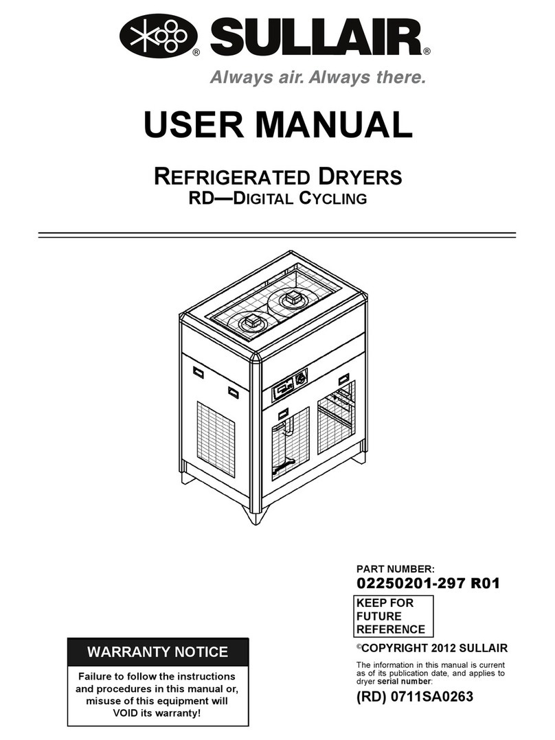
Sullair RH Series Troubleshooting guide

Failure to follow the instructions
and procedures in this manual or,
misuse of this equipment will
VOID its warranty!
WARRANTY NOTICE
USER/SERVICE MANUAL
REFRIGERATED DRYERS
RH—HIGH TEMPERATURE
RN—NON-CYCLING
RD—DIGITAL CYCLING
PART NUMBER:
KEEP FOR
FUTURE
REFERENCE
©SULLAIR CORPORATION
02250195-401 R00
The information in this manual is current
as of its publication date, and applies to
compressor serial number:
(RH) 0611SA0198
(RN) 4810SA0001
(RD) 0711SA0263
and all subsequent serial numbers.

AIR CARE SEMINAR TRAINING
Sullair Air Care Seminars are courses that provide hands-on instruction for the proper operation, maintenance,
and servicing of Sullair products. Individual seminars on Industrial compressors and compressor electrical
systems are offered at regular intervals throughout the year at Sullair’s corporate headquarters training facility
located at Michigan City, Indiana.
Instruction includes training on the function and installation of Sullair service parts, troubleshooting common
faults and malfunctions, and actual equipment operation. These seminars are recommended for maintenance,
contractor maintenance, and service personnel.
For detailed course outlines, schedule, and cost information contact:
SULLAIR TRAINING DEPARTMENT
1-888-SULLAIR or
219-879-5451 (ext. 5623)
www.sullair.com
- Or Write -
Sullair Corporation
3700 E. Michigan Blvd.
Michigan City, IN 46360
Attn: Service Training Department.

TABLE OF CONTENTS
SECTION 1—SAFETY
7 1.1 SAFETY INFORMATION
SECTION 2—RH SERIES REFRIGERATED HIGH TEMPERATURE
COMPRESSED AIR DRYER
10 2.1 SPECIFICATIONS
10 2.2 INTRODUCTION
11 2.3 TYPICAL INSTALLATION
12 2.4 SAFETY REGULATIONS
15 2.5 REFRIGERANT DRYER FEATURES
17 2.6 DRYER OPERATION PROCEDURE
18 2.7 ED—RH15-50
20 2.8 ED—RH75-100
22 2.9 ID—RH15-50
24 2.10 ID—RH75-100
26 2.11 P&I—RH15-75
28 2.12 P&I—RH100
30 2.13 WIRING DIAGRAM
32 2.14 TROUBLESHOOTING
37 2.15 SETTINGS
38 2.16 SPARE PARTS
SECTION 3—RN & RD SERIES REFRIGERATED NON-CYCLING
COMPRESSED AIR DRYER
41 3.1 INTRODUCTION
41 3.2 SPECIFICATIONS
42 3.3 SAFETY INSTRUCTIONS
42 3.4 ISSUES TO AVOID
42 3.5 RECEIVING AND INSPECTION
42 3.6 TRANSPORTATION
43 3.7 INSTALLATION LAYOUT REQUIREMENTS
43 3.8 ENVIRONMENTAL PROTECTION
43 3.9 PRODUCT DESCRIPTION

TABLE OF CONTENTS
43 3.10 PRODUCT FEATURES
45 3.11 PRINCIPLE OF OPERATION
45 3.12 COMPRESSED AIR HEAT EXCHANGER
46 3.13 PIPE/CONNECTION REQUIREMENTS
46 3.14 ELECTRICAL CONNECTION REQUIREMENTS
46 3.15 OPERATING PRECAUTIONS
47 3.16 INSTALLATION
48 3.17 STEPS TO UNDERTAKE BEFORE OPERATING
48 3.18 OPERATING PROCEDURES
49 3.19 STARTUP AND SHUT DOWN PROCEDURE
50 3.20 ED—RN 5-15
52 3.21 ED—RN 25
54 3.22 ED—RN 35-50
56 3.23 ED—RN 75
58 3.24 ED—RN 100
60 3.25 ED—RN 125
62 3.26 ED—RN 150
64 3.27 ED—RN 175
66 3.28 ED—RN 200
68 3.29 ED—RN 250
70 3.30 ED—RN 325 (230)
72 3.31 ED—RN 325 (460)
74 3.32 ID—RN5-15
76 3.33 ID—RN25
78 3.34 ID—RN35/50
80 3.35 ID—RN75-100
82 3.36 ID—RN125
84 3.37 ID—RN150
86 3.38 ID—RN175-200
88 3.39 ID—RN250-400
90 3.40 P&I—RN5-10-15-25
92 3.41 P&I—RN35-75
94 3.42 P&I—RN100-200
96 3.43 P&I—RN250-325
97 3.44 P&I—RD400-500-700-850
98 3.45 P&I—RD700-850
99 3.46 P&I—RD1000-1200-1600-2000-2400-3000-3800-5000-6000
100 3.47 P&I—RD1000-1200-1600-2000-2400-3000-3800-5000-6000
102 3.48 WIRING DIAGRAM—RN5-10-15-20-25
104 3.49 WIRING DIAGRAM—RN35-50-75-100
106 3.50 WIRING DIAGRAM—RN125-150
108 3.51 WIRING DIAGRAM—RN175
110 3.52 WIRING DIAGRAM—RN200

TABLE OF CONTENTS
112 3.53 WIRING DIAGRAM—RN250-325
114 3.54 WIRING DIAGRAM—RN250-325 (230-3-60-A)
116 3.55 WIRING DIAGRAM—RN250-325 (230-3-60-A)
118 3.56 WIRING DIAGRAM—RN250-325 (460-3-60-A, 400-3-50-A)
120 3.57 WIRING DIAGRAM—RN250-325 (460-3-60-A, 400-3-50-A)
122 3.58 CONTROL CIRCUIT—RN250-325
124 3.59 POWER CIRCUIT—RN250-325
126 3.60 MAINTENANCE
127 3.61 REPLACEMENT PARTS
1283.62TROUBLESHOOTING
134 3.63 SETTINGS
144 3.64 SPARE PARTS LIST
SECTION 4—E-680 CONTROLLER FOR REFRIGERANT DRYERS
159 4.1 DESCRIPTION
159 4.2 OPERATION
166 4.3 ED—RD400
168 4.4 ED—RD500
170 4.5 ED—RD700
172 4.6 ED—RD700 AIR COOLED
174 4.7 ED—RD850
176 4.8 ED—RD850 AIR COOLED
178 4.9 ED—RD1000
180 4.10 ED—RD1000 AIR COOLED
182 4.11 ED—RD1200 AIR COOLED
184 4.12 ED—RD1600 AIR COOLED
186 4.13 ED—RD2000 AIR COOLED
188 4.14 ED—RD2400 AIR COOLED
190 4.15 ED—RD3000 AIR COOLED
192 4.16 ED—RD3800 AIR COOLED
194 4.17 ED—RD5000 AIR COOLED
196 4.18 ED—RD6000 AIR COOLED
1984.19ID—RD400
2004.20ID—RD500-850
202 4.21 ID—RD1000-1200 AIR COOLED
204 4.22 ID—RD1000-1200 WATER COOLED
206 4.23 ID—RD1600-2000 AIR COOLED
208 4.24 ID—RD1600-2000 WATER COOLED
210 4.25 ID—RD2400-3000 AIR COOLED
212 4.26 ID—RD2400-3000 WATER COOLED
214 4.27 ID—RD3800 AIR COOLED
216 4.28 ID—RD3800 WATER COOLED
218 4.29 P&I—RD400

TABLE OF CONTENTS
220 4.30 P&I—RD500-850
222 4.31 P&I—RD700-850
224 4.32 P&I—RD1000-6000
226 4.33 P&I—RD1000-6000
228 4.34 WIRING DIAGRAM—RD400 (230-3-60-A)
230 4.35 WIRING DIAGRAM—RD400 (230-3-60-A)
232 4.36 WIRING DIAGRAM—RD400 (460-3-60-A, 400-3-50-A)
234 4.37 WIRING DIAGRAM—RD400 (460-3-60-A, 400-3-50-A)
236 4.38 WIRING DIAGRAM—RD500/700 (230-3-60-A)
238 4.39 WIRING DIAGRAM—RD500/700 (230-3-60-A)
240 4.40 WIRING DIAGRAM—RD (500/700/850-1000-1200-1600-2000-2400-
3000-3800-5000-6000)-460-3-60-A, 400-3-50-A
242 4.41 WIRING DIAGRAM—RD (500/700/850-1000-1200-1600-2000-2400-
3000-3800-5000-6000)-460-3-60-A, 400-3-50-A
244 4.42 WIRING DIAGRAM—RD700-850 (230-3-60-W)
246 4.43 WIRING DIAGRAM—RD700-850 (230-3-60-W)
248 4.44 WIRING DIAGRAM—RD (700-850-1000-1200-1600-2000-2400-3000-
3800-5000-6000) 460-3-60-W, 400-3-50-W
250 4.45 WIRING DIAGRAM—RD (700-850-1000-1200-1600-2000-2400-3000-
3800-5000-6000) 460-3-60-W, 400-3-50-W
252 4.46 CONTROL CIRCUIT—RD400-500-700-850-1000-1200-1600-2000-2400-
3000-3800-5000-6000
254 4.47 POWER CIRCUIT—RD400-500-700-850-1000-1200-1600-2000-2400-
3000-3800-5000-6000
258 4.48 SPARE PARTS

Section 1
7
SAFETY
SAFETY
The dryer has been designed and constructed in
accordance with the generally recognized rules
pertaining to refrigeration technology as well as
industrial safety and accident prevention regulations.
The equipment design, development, production,
assembly and customer service fall under the Sullair
quality control system.
The dryer is state of the art. There are, however,
hazards to the body, equipment and life
accompanying this type of product if it is not operated
for the purpose which it is intended by trained and
specialized personnel.
The equipment supplied is intended exclusively for
drying compressed air. Any other use or one
exceeding this is considered unauthorized. Sullair
cannot be held liable for damages resulting from
incorrect or unauthorized use of the equipment. Any
such risk is carried solely by the end user.
Authorized use means complete compliance with all
of the conditions of operation, servicing and
maintenance prescribed by Sullair in this Instruction
and Operation Manual.
The dryer is only to be operated, serviced and
repaired by trained personnel who are familiar with
this type of equipment and understand fully its
operation and any potential dangers.
1.1 SAFETY INFORMATION
The end user and operator must observe all National,
State, and Local industrial and safety regulations
dealing with the operation of pressure vessels under
compressed air service. Also all “end user” safety
rules for the same type of service must be adhered
to. The following points list some of the important
factors dealing with this type of equipment.
• Never make any constructional changes to
the equipment
• Use only original spare parts and accesso-
ries
• Never weld on any pressure vessel or mod-
ify it in any way
• All maintenance on “pressure parts” must
be carried out with the equipment shut-
down, depressurized and locked out. Any
in plant procedures or work permits regard-
ing pressure vessels are to be adhered to.
• Do not operate the equipment with the con-
trol panel door open, the electrical system
energized and live parts exposed.
• Disconnect the dryer from the electrical
supply when any electrical work is per-
formed. Lock out the safety disconnect and
obtain any required work permits.

8
NOTES

Section 2
9
RH SERIES—HIGH TEMPERATURE
RH SERIES REFRIGERATED HIGH TEMPERATURE
COMPRESSED AIR DRYER
RH-0015-115-60-A RH-0025-115-60-A RH-0035-115-60-A RH-0075-115-60-A RH-0100-115-60-A

RH SERIES—HIGH TEMPERATURE SECTION 2
10
2.1 SPECIFICATIONS
Pay attention to the Minimum and Maximum
operating conditions before installing and operating
the dryer.
If your application does not match the above criteria,
contact your Sullair distributor and they will be able to
provide the right dryer for your application.
2.2 INTRODUCTION
The RH series of Non-cycling Refrigerated Air Dryers
are specially designed for compressed air systems
that do not use an after cooler. The hot compressed
air from the compressor enters the downstream
receiver tank where condensed moisture is removed
with an automatic drain. The hot saturated air is then
passed directly into the RH series of dryers.
RH series of non-cycling refrigerant compressed air
dryers have been designed to remove water vapor
from industrial compressed air that is free of reactive
contaminants like ammonia, gaseous acid, dust, rust
or any other chemical or mineral products capable of
reacting or clogging the heat exchanger. The dryers
are designed and recommended for indoor
applications.
Normal Operating Pressure 175 PSIG
Normal Operating Temperature 200 Deg. F
Normal Ambient Temperature 100 Deg. F
Maximum Operating Pressure 230 PSIG
Minimum Operating Pressure 80 PSIG
Maximum Ambient Temperature 120 Deg. F
Minimum Ambient Temperature 40 Deg. F
Maximum Operating Temperature 240 Deg. F

SECTION 2 RH SERIES—HIGH TEMPERATURE
11
2.3 TYPICAL INSTALLATION
The RH series of Dryers operate without the need for any after-coolers.

RH SERIES—HIGH TEMPERATURE SECTION 2
12
2.4 SAFETY REGULATIONS
2.4.1 IMPORTANT SAFETY NOTES:
1. When operating the air dryer the operator
must employ safe working methods and
observe all recommended/local safety
instructions and applicable regulations.
2. Prior to installation, the dryer and the com-
pressed air system must be depressurized
and disconnected from the electrical main
supply.
3. The user is responsible for safe operating
conditions. Parts and accessories must be
replaced if inspection shows that safe opera-
tion cannot be assured.
4. Installation, operation, maintenance and
repair are to be performed only by autho-
rized, trained and certified technicians.
5. DO NOT exceed the minimum and maximum
values of all the parameters mentioned on
the Main data label, Electrical data label and
accompanying specification sheets if any.
6. All safety precautions mentioned in this
manual must be adhered to at all times and
by all personnel working on the dryer
2.4.2 TRANSPORTATION
1. Use care and caution when transporting the
dryer. Avoid sudden jerks, tilting, dropping
and other physical abuse.
2. A forklift can be used to transport the dryer
provided the forks are long enough to sup-
port the full width or length. Caution must be
used throughout the move.
2.4.3 POSITIONING
1. The dryer must be installed horizontally. A
minimum of at least 1 ½ feet clearance
around the dryer is necessary to allow free
air circulation and easy access for servicing.
2. The ambient temperature in the room
should not exceed 120° F and should not
be below 40° F, taking into account the
heat radiated by the dryer. (About 18 watts
for each SCFM under ISO 7183-5 condition
or 40 watt for each liter/sec under ISO 7183-
A condition).
2.4.4 INSTALLATION
In addition to the general mechanical construction
procedures and local regulations, the following
instructions need to be emphasized:
1. Only authorized, trained and skilled engi-
neers should install the compressed air
dryer.
2. Safety devices, protecting covers or insula-
tions in the dryer are never to be removed or
modified. Each pressure vessel or acces-
sory installed outside the dryer with com-
pressed air (Any pressure above
atmospheric pressure) must be fitted with
individual pressure relief safety valves.
3. Optional air by-pass valve: Install one (1) air
by-pass valve and two (2) switch off valves in
the line before the dryer to allow easy main-
tenance and for possible isolation of the
dryer without interrupting the compressed air
flow.
4. In Line Filter: install one compressed air filter
in line before the dryer to protect it against
dirt and possible clogging of heat exchanger.
Contact your Sullair representative/dealer for
suitable filter.
2.4.5 STEPS TO UNDERTAKE BEFORE
OPERATING
1. Read this manual completely.
2. Review all safety precautions.
3. Use recommended pipe sizes as per specifi-
cations.
4. Never operate the dryer at pressures above
the maximum specified on the dryer label
(check the technical specifications).

SECTION 2 RH SERIES—HIGH TEMPERATURE
13
2.4.6 MAINTENANCE BY AN ENGINEER/
TECHNICIAN
1. Maintenance and repairs should only be
performed when the air dryer is shut down
and depressurized and when the main
power switch is turned OFF.
2. Use only the appropriate tools for mainte-
nance and repair.
3. Before dismantling any part that has been
pressurized, disconnect the pressure
sources and depressurize the system com-
pletely. Shut off all valves and isolate the
dryer.
4. Proceed carefully during maintenance and
repair. Prevent dirt from entering by covering
parts and orifices with a clean cloth, paper or
tape.
5. Receiver tanks should never be welded or
modified in any way.
6. Never leave tools, loose parts or cleaning
rags in or on the air dryer.
7. Before connecting the dryer back online,
check the setting of the control and safety
devices as well as the pressure and the tem-
perature of the compressed air circuit.
2.4.7 MAINTENANCE BY THE USER
1. Keep the dryer clean.
2. In case of more than 4 pounds of refriger-
ant, the dryer should be regularly checked
to be leak free by qualified refrigerant
engineer. Refer to section “Environmental
protection” of this manual.
3. Every six months— check the correct
operation of the condenser drain trap.
Replace timer or solenoid valve in case of
clogging or malfunctioning.
4. Every six months—check and clean the
drain strainer or the electronic sensor by
undoing the access screw and rinsing the
filter with tap water to remove the trapped
dirt from the inside.
5. Clean the air condenser with a brush or
compressed air as soon as it’s dirty or
clogged: Take care not to bend the fins of
the condenser heat exchanger.
6. Check the troubleshooting list in case of
maintenance issues.
7. Check operating pressures, temperatures
and time settings after maintenance. If oper-
ating and safety devices function properly,
the air dryer may be used.
2.4.8 ENVIRONMENTAL PROTECTION
1. US/EU laws protect the environment against
refrigerant being released into the atmo-
sphere.
2. An annual leak control test at less than 5.0
gr/year should be performed by a qualified
engineer if the refrigerant dryer contains
more than 4.4 lbs/ 2 kg of refrigerant. This
control test has to be done twice a year if the
dryer contains more than 66 lbs/30 kg.
3. Prior to dryer disposal, the refrigerant must
be properly recovered by a qualified engi-
neer.

RH SERIES—HIGH TEMPERATURE SECTION 2
14
2.4.9 REFRIGERANT CIRCUIT:
The refrigerant circuit can be divided into 3 parts:
1. Low pressure section with an evaporator
(heat exchanger)
2. High pressure section including: Condenser,
liquid receiver, (if installed) and the filter
dryer.
3. Control circuit including: Compressor, expan-
sion valve, by-pass valve (if installed), fan
pressure switch, safety high pressure switch.
2.4.10 THE REFRIGERANT CIRCUIT OPERATES
AS FOLLOWS:
1. The compressor compresses gaseous refrig-
erant.
2. The hot refrigerant gas condenses in the
condenser. Being liquefied, it is stored in the
liquid receiver (if existing).
3. The liquid is taken out of the storage receiver
vessel and injected into the evaporator (heat
exchanger) by an expansion valve. This
expansion valve is protected by a filter dryer,
that retains particles and humidity that could
be in the circuit.
4. The injected liquid fills in the refrigerant sec-
tion of the Air-Refrigerant heat exchanger
and evaporates due to the heat from the
incoming air. The gaseous refrigerant is
sucked in the compressor and the cycle car-
ries on.
5. In order to keep the evaporation pressure
steady, and thus the refrigerant temperature
in the heat exchanger, a by-pass valve
injects hot gaseous refrigerant into the cir-
cuit. On certain dryers, an automatic pres-
sure expansion valve regulates this process.
2.4.11 COMPRESSED AIR CIRCUIT
1. The hot, saturated, compressed air from the
compressor is forced into the air-cooled
after-cooler where it is pre-cooled to approxi-
mately ambient temperature.
2. This pre-cooled compressed air enters the
high-efficiency moisture separator where
condensed moisture is stripped from the air
stream and purged out via the electronic
timer drain.
3. The air then enters the first stage of the heat
exchanger (air to air pre-cooler/re-heater)
where the outgoing chilled air cools the
incoming hot air. This energy saving heat
exchanger provides significant advantages,
such as a reduction of the heat load imposed
on the refrigerant compressor and con-
denser, re-heating the outlet air, and prevent-
ing condensation of moisture in the plant air
distribution lines.
4. From the air-to-air heat exchanger, air enters
the air-to-refrigerant heat exchanger where
further cooling occurs and the air tempera-
ture is reduced to the desired pressure dew
point (PDP). As the air is cooled, the mois-
ture condenses into a liquid and is then sep-
arated in the integrated high efficiency
separator and discharged through the con-
densate drain.
5. The cooled air then re-enters the air-to-air
heat exchanger, in a direction opposite to the
flow of the warm, saturated incoming air and
pre-cools the hot air. During this process the
outgoing air is reheated thereby minimizing
the chances of moisture condensation in the
compressed air distribution lines.

SECTION 2 RH SERIES—HIGH TEMPERATURE
15
2.5 REFRIGERANT DRYER
FEATURES
2.5.1 COMPRESSOR TYPE
The High Temperature Inlet Refrigerated
compressed air dryers use the sealed Hermetic type
of compressors and require no periodic servicing.
2.5.2 CONDENSER
The air-cooled condenser is equipped with
helicoidally fans controlled by a pressure switch the
controls the fan cycling in order to maintain the
refrigerant high pressure at the correct level.
Air cooled aftercooler is integrated to the condenser.
The fan motor of the air cooled aftercooler is
separate and it only starts to function when the inlet
air temperature is equal or above 95°F. This is
controlled by a thermostatic switch.
2.5.3 REFRIGERANT CIRCUIT PROTECTION
OVERLOAD PROTECTOR:
The single phase compressors are equipped with an
overload protector which is a thermal sensitive
switch controlling the temperature of the compressor
and overheating. In case of malfunction, the
protector trips out. However, it switches on again
automatically as soon as the compressor has cooled
down.
HIGH PRESSURE SECURITY SWITCH:
Refrigerant circuits are protected against excessive
pressure by a security switch that stops the
compressor in case of too high a pressure. In case
this safety switch has tripped, it has to be manually
reset before switching on the dryer.
2.5.4 FILTER DRYER
In order to keep the refrigerant circuit void of all
moisture, a filter drier is used in line. This filter also
traps any solid particles that may have migrated in
the circuit during operation. To avoid problems, the
refrigerant circuit must be vacuumed before filling it
with the recommended refrigerant.
2.5.5 REFRIGERANT CIRCUIT REGULATION
1. The evaporating pressure is kept constant
by controlled injection of hot gas from the
high-pressure side into the low-pressure
section of the circuit through a by-pass valve.
This constant pressure corresponds to a sta-
ble evaporating temperature adjusted as
close to 32°F as possible.
2. The liquid refrigerant is injected into the
evaporator through a thermostatic expansion
valve keeping the superheat of the refriger-
ant constant at the outlet of the evaporator.
3. The mix of hot gas from by-pass valve and
cold gas from evaporator is called superheat.
2.5.6 CONDENSATE DRAIN—TRAP ASSEMBLY
Disassembling the drain is easy because it can be
isolated from the air circuit under pressure with a ball
valve. The drain has to be isolated before being
dismantled.

RH SERIES—HIGH TEMPERATURE SECTION 2
16
2.5.7 COMPACT 3-IN-1 HEAT EXCHANGER
The dryers are equipped with compact heat
exchangers. This compact 3-in-1 setup has been
specially designed to dry compressed air and is
made of the following components:
1. An air-to-air heat exchanger which pre-cools
the incoming hot air with the outgoing cold
air, thereby saving a significant load on the
compressor.
2. An Evaporator which is an air-to- refrigerant
heat exchanger that cools the pre-cooled
compressed air.
3. An integrated separator that removes all
condensates and requires no additional
maintenance.
AIR/REF.
AIR INLET
DRAIN PORT
AIR OUTLET
REFRIGERANT
GAS OUTLET
REFRIGERANT
GAS INLET
AIR/AIRWATER SEPARATOR

17
NOTES
2.6 DRYER OPERATION
PROCEDURE
1. Starting of a Single phase dryer for the first
time
a. Make sure all air connections are intact and
have no leaks
b. Double check wiring connections
c. Set the rocker switch to “I”
2. Daily starting and shut-down
a. Push on the green button to start the dryer.
b. The start light will indicate that the dryer is
running.
3. To stop the dryer, first stop the airflow (either
shut-down the air compressor or close the
inlet/outlet or by-pass valve). When the air
flow is stopped, push the green button to the
stop position.
NOTE
1. Avoid turning OFF the dryer when com-
pressed air is still flowing through it.
2. To switch the already preheated dryer
on again, simply push the green start
button.

RH SERIES—HIGH TEMPERATURE SECTION 2
18
2.7 ED—RH15-50
02250195-252 R00

SECTION 2 RH SERIES—HIGH TEMPERATURE
19
2.7 ED—RH15-50
KEY PART NUMBER DESCRIPTION QTY
1 SEE REF. TABLE COMPRESSOR 1
2 M-CON-0050H CONDENSOR 1
3 M-FMT-0150-115-1-60-A FAN MOTOR 2
4 M-FAN-0150 FAN BLADE 2
5 M-GRL-0150 FAN GRILL 2
6 M-DRI-0200 DRIER DEHYDRATOR 1
7 M-EXC-0035 HEAT EXCHANGER 1
8 TMR-3000 TIMER 2
9 M-SLV-0150-115 SOLENOID VALVE 1
10 M-WSP-050 WATER SEPARATOR 1
11 M-EXV-0075 EXPANSION VALVE 1
12 M-HPS-0200 HIGH PRESSURE SWITCH 1
13 M-FNS-0200 FAN ON/OFF SWITCH 1
14 M-THS-0325 THERMOSTATIC SWITCH 1
15 M-THG-0325 THERMOSTATIC GUAGE 1
16 M-ONB-0200 ON/OFF BUTTON 1
17 M-CFR-0050H CABINET FRONT 1
18 M-CLE-0050H CABINET SIDE-LEFT 1
19 M-CRI-0050H CABINET SIDE-RIGHT 1
20 M-CRE-0050H CABINET REAR 1
21 M-CTO-0050H CABINET TOP 1
22 M-CBA-0050H CABINET BASE 1
23 M-CBL-0050H CABINET LEG 4
24 M-HP1-0050H CABINETHORIZONTAL PROFILE 1 2
25 M-HP2-0050H CABINET HORIZONTAL PROFILE 2 2
26 M-CTC-3000 CABINET TOP CORNER 4
27 M-CPS-3000 CABINET HANDLE 3
28 M-PDC-0200 PLASTIC DISPLAY COVER 1
29 M-SCR-3000 SCREW TYPE 1 24
30 M-STU-3000 CABINET STUD AND NUT 12
31 M-FAS-3000 CABINET FASTENER 12
32 M-CSC-0050-115-1-60 COMPRESSOR START CAPACITOR 1
33 SEE REF. TABLE
COMPRESSOR OVERLOAD
PROTECTOR 1
34 M-STR-0050-115-1-60 COMPRESSOR START RELAY
KEY PART NUMBER DESCRIPTION QTY

RH SERIES—HIGH TEMPERATURE SECTION 2
20
2.8 ED—RH75-100
02250195-253 R00
This manual suits for next models
167
Table of contents
Other Sullair Dryer manuals

Sullair
Sullair SR-250 User manual
Sullair
Sullair DMD Series Troubleshooting guide

Sullair
Sullair SRL-1200 User manual

Sullair
Sullair SR-125 User manual

Sullair
Sullair SAR 180 User manual
Sullair
Sullair SRL Series User manual

Sullair
Sullair SRV-250 User manual

Sullair
Sullair DEX Series Troubleshooting guide
Sullair
Sullair SRC Series User manual

Sullair
Sullair SR-5 User manual
