Sullair SR-250 User manual

272781
EN
F
ES
P
D
DATE: 15.12.2003 ISSUE: 2 CODE: 02250145-- 604
VALID FROM SERIAL NUMBER: 2532980001
User manual
Page 1
Manuel d’utilisation
Page 13
Manual de uso
Página 25
Manual do utilizador
Página 37
Benutzerhandbuch
Seite 49
SR-- 250 --- SR-- 3000
refrigeration dryer (60Hz)

1
Code: 02250145-- 604 SR-- 250 --- SR-- 3000
English
Index
1Introduction page2
1.1 Foreword page 2
1.2 Packaging page 2
1.3 Transport page 2
1.4 Storage page 2
1.5 Inspection page 2
2 Installation page 2
2.1 Electrical connection page 3
2.2 Condensate drian connection page 3
3 Start---up and operation page 4
3.1 Preliminary checks page 4
3.2 Starting the dryer page 4
3.3 Stopping the dryer page 4
3.4 Operation page 4
4 The control panel page 5
4.1 Front panel page 5
4.2 Operation page 6
4.3 General functions page 6
4.4 Alarms and Warnings page 7
5 Maintenance page 9
5.1 Preventive maintenance page 9
5.2 Disassembling the unit page 10
5.3 Refrigerant leaks in the refrigeration circuit page 10
5.4 Refrigerant charging page 10
6Calibration page10
7 Spare parts list page 10
8 Troubleshooting page 11
Safety warnings
Important:
SKeep this manual with the machine throughout its entire service life.
SCarefully read this manual before carrying out any operation on the machine.
SThis machine is designed for PROFESSIONAL USE only. Only use the ma-
chine for the purpose for which it is intended. Improper use of the machine
absolves the manufacturer from all liability.
This manual has been compiled to help the final user perform just those opera-
tions which do not require removal of the panels.
All other operations which involve the removal of covers from instruments or
electrical circuit--- breakers using special tools must only be carried out by
trained personnel due to the danger of rotating parts or live components.
Tampering with, or substitution of, any component by unauthorized personnel
invalidates the warranty.
Each machine is equipped with an electric disconnect device which allows the op-
erator to work on the machine in absolute safety. This device must always be used
to disconnect the mains supply to avoid any risk of danger during maintenance
work (electric shocks, scalding, automatic start---up, moving parts and remote
control).
Before servicing the dryer always make sure the compressed air circuit is depres-
surised.
When requesting technical assistance or ordering spare parts, always quote the
model and serial number on the identification plate mounted externally on the
unit.
IMPORTANT: This manual is subject to modification. For the most comprehensi-
ve and up---to--- date information, the user is therefore required to consult the ma-
nual supplied with the machine.

2
Code: 02250145-- 604 SR-- 250 --- SR-- 3000
English
2
All figures to which the “see Fig.” references in this text refer can be found at the
end of this manual. The language translations for these figures can be found in the
Legend (A3---sized page) inserted after all the figures.
1Introduction
1.1 Foreword
The SR dryers are designed to guarantee high quality compressed air and minimum
maintenance.
Please carefully read this manual to obtain maximum performance from your dryer
and ensure its correct installation and start--- up in compliance with manufacturer in-
structions.
1.2 Packaging
The dryer is packaged with a strong cardboard box strapped to a wooden pallet.
Instruction symbols (UNI ISO 780) for the movement, transport and stocking of the
product are printed on two sides of the packing.
FRAGILE: HANDLE
WITH CARE
THIS WAY UP
KEEP DRY DO NOT ROLL STACKING
LIMITATION
USE NO HOOKS
Kg max
1.3 Transport
SKeep the unit in an upright position and do not leave it outdoors.
SUse a forklift truck to move the machine.
SCare should be taken to avoid damaging internal components through poor han-
dling during movement, installation or use.
SUnpack the machine as close as possible to the installation site.
SEnsure the ambient temperature never exceeds 122˚F(50˚C).
1.4 Storage
If stored the packaged units must be kept inside, protected from humidity, direct
sunlight and rain, and at a temperature not exceeding 122˚F(50˚C).
Moreover, although stacking is permitted the maximum weight must not be more
than the value shown on the packaging.
1.5 Inspection
On receipt of the machine, make sure it has incurred no damage during transit.
If any damage is detected promptly contact the haulage company.
2 Installation
(see Fig. 4 / Fig. 5)
a) Dryer should be installed indoors; where this is not possible it must however be
installed in a clean dry area, with a temperature within the limits 41---122˚F
( 5 --- 5 0 ˚C), and sheltered from the effects of direct weather (including direct sun-
light).
b) The compressed air inlet temperature must never exceed 140˚F(60˚C). For dif-
ferent temperatures to those indicated above, consult the manufacturer.
c) Allow for a 60 inch (1,5 metre) gap around the unit to facilitate maintenance and
ensure unimpeded air discharge from the condenser.
Air--cooled versions: leave a space of at least 80 inch (2 metre) above the Dryer.
d) For most compressed air applications we recommend following the installation
plan (see Fig. 1). This layout ensures optimum compressor, filter and dryer per-
formance and also guarantees excellent air quality whilst minimising operating
costs.
e) Donotobstructthedryerairgrilles.
f) Avoid recirculation of hot condenser air back into the condenser air inlet.

3
Code: 02250145-- 604 SR-- 250 --- SR-- 3000
English
g) If the system is prone to instantaneous pressure surges which exceed the dryer’s
rated capacity, mount a suitably sized receiver near the overpressure source. For
more precise information, contact the manufacturer or distributor.
h) It is necessary install a pre---filter (max. 3 micron) on the dryer intake to prevent
rust, scale or other pollutants from entering the system and clogging the conden-
sate drain and heat exchangers, thereby causing severe pressure drops.
This filter must be close to the dryer inlet.
i) For water cooled versions it is recommended to install a filter on the condenser
water inlet to prevent the ingress of debris that will gradually choke the passages,
with negative effects on dryer performance.
j) Water-- cooled versions
WATER QUALITY RECOMMENDATIONS
The water quality should satisfy the following conditions:
Parameter Concentration Parameter Concentration
Langelier Index 0 --- 1 Iron (Fe) <0,2 ppm
pH 7 . 5 --- 9 Nitrate (NO
3
)<2 ppm
Sulfate (SO
42 ---
)<50 ppm Alkalinity (HCO
3---
)70---300 ppm
Electrical conductivity 10---500µS/cm Hydrogen Sulfide (H
2
S) <0.05 ppm
Ammonia (NH
3
)<1 ppm Free CO
2
<5 ppm
Chloride (Cl
---
)<50 ppm Aluminium (Al) <0.2 ppm
To t a l H a r d n e s s 70---150 ppm CaCO
3
Condenser cooling 43.5---145 psig
Oxygen <0.1 ppm
C
o
n
d
e
n
s
e
r
c
o
o
l
i
n
g
water pressure
4
3
.
5
1
4
5
p
s
i
g
(3---10 barg)
k) Always install a bypass line with shut---off valves (supplied as option for SR-250
-- SR-500) to permit maintenance or calibration without interrupting the com-
pressed air flow to the user.
l) Correctly connect the dryer to the air inlet and outlet connections. If the com-
pressed air network is prone to vibrations, use hoses to make the connections.
If the mains is subject to high levels of pulsation, ensure that the connection is
equipped with pulsation dampers.
m) Do not connect condensate drains common to other pressurised drain lines in a
closed circuit. Make sure the outflow from the condensate drains is unimpeded.
Connect the condensate piping in such a way to ensure that sound levels are kept
to a minimum during drainage.
Ensure that all condensate is disposed of in a responsible manner, in accordance
with local norms concerning environmental protection.
n) The ambient air around the dryer and compressor must not contain solid or gas-
eous contaminants. All compressed and condensed gases can generate acids or
chemical products which may damage the compressor or components inside the
dryer.
Take particular care with sulphur, ammonia, chlorine and installations in marine
environments. For further advice or assistance consult the manufacturer.
2.1 Electrical connection (see Fig. 5 / Fig. 10)
Use a cable that complies with regulations inforce in the countryof installation(con-
nected to terminals “L1 and L2 ” for single---phase machines and to terminals
“ L 1 --- L 2 --- L 3 --- G N D ” for three---phase machines), connected to the junction
box, with minimum wire sizes: (see machine electrical schematic in Fig. 10).
Install an overcurrent and earth leakage circuit breaker upstream from the
plant (IDn = 0.3A) with a 0.12 inch (3 mm) gap between contacts when open (refer
also to local laws).
2.2 Condensate drain connection
a) The drainer is already installed and cabled.
b) Connect the condensate drain outlet to the drainage system.
c) Any maintenance operation must be done by an expert technician.
N.B.: The dryer is supplied either with a timed drain or an electronic level sensing
drain. Refer to the separate manual supplied with the dryer for specific details con-
cerning the condensate drain.

4
Code: 02250145-- 604 SR-- 250 --- SR-- 3000
English
4
3 Start---up and operation
N.B.: For instructions on operation of control panel, refer to Chapter 4.
3.1 Preliminary checks
Beforestartingupthedryer,makesurethat:
a) the air inlet valves are closed and there is no air flow through the dryer.
b) The mains power supply is commensurate with the dryer voltage.
c) The dryer is installed in compliance with the installation instructions given in
Chapter 2.
3.2 Starting the dryer
a) The dryer is started using the main switch.
b) Always start up the dryer before activating the air compressor.
c) Set the yellow--- red main disconnect switch QS to ON so that the (yellow) power
on LED on the control panel illuminates.
d) Wait about 5 minutes until the dryer is running at the correct operating tempera-
tures and pressures.
e) Slowly open the air inlet valve to pressurise the dryer.
f) Slowly open the air outlet valve. The dryer is now operating (drying).
g) Always leave the dryer running while the air compressor is operating.
h) It is
v
ery important to check the rotational direction of the SCRO
L
L
compressors. If supplied with the wrong phase frequency they will turn
in the opposite direction. In this case they are very noisy and risk getting
damaged. SWAP OVER THE PHASES IMMEDIATELY.
Check that the pressure reading on the (LP) gauge, situated on the front
panel, decreases.
3.3 Stopping the dryer
a) The dryer is stopped using the main switch.
b) Stop the dryer 2 minutes after shutting down the air compressor or interrupting
the air flow to the dryer.
Avoidallowingcompressedairtoenterthedr
y
er when the dr
y
er is
switchedofforwhenitisinanalarmsituationwhichstopstherefrigeration
compressor.
3.4 Operation
SThe dryer operates automatically. It is factory set for a dew point of 37˚F(3˚C)
(ISO 7183, Part 2) and therefore requires no further calibration.
SDo not exceed the machine’s design limits, bypass excess air flow and check the
unit model and/or installation.
SFor maximum performance from your dryer, follow the maintenance schedule de-
scribed in Chapter 5.
SThe sound pressure level recorded for these dryers at 40 inch (1 metre) from the
machine in free field conditions) is less then 70 dB (A).
SFig. 6 shows the Dryer’s refrigeration and air circuits.

5
Code: 02250145-- 604 SR-- 250 --- SR-- 3000
English
4 The control panel
4.1 Front panel
All operations are controlled and displayed on the front panel:
display
Display
SWhen the unit is powered up, the unit of measure (˚Cor˚F) of the indicated tem-
perature will be displayed.
SDuring normal operation, the dew point temperature (T0) will be displayed.
SWhen the dryer is in an alarm state, the alarm code will be displayed.
SIn STATUS REPORT mode, the display indicates the most recent dryer status
events.
SIn the case of high dew point conditions, the temperature reading and Hd warning
code are displayed alternately.
SIn the case of low dew point conditions, the temperature reading and Ld alarm
code are displayed alternately.
Keypad
on off
Dryer on/off button.
When the dryer is off, the following functions are enabled:
a) setting the last SERVICE DATE;
b) entering and adjusting the operating parameters;
c) read ing t he STATUS REPORT.
reset
If pressed when an alarm is in progress, it resets the alarm or the
warning when the cause no longer exists.
This is also used for the following functions:
a) temperature scale selection;
b) reset alarm memory;
c) setting last service date;
d) compressor hours counter reading.
report
Acce ss to S TAT US REPORT.
LEDs
a
l
a
r
m
(
r
e
d
)
ALARM
red LED illuminated One or more alarms tripped.
a
l
arm
(
re
d
)
WARNING
flashing red LED
Oneormorewarningsignals
tripped.
off remote (yellow) REMOTE OFF
yellow LED illuminated
Dryer switched off by remote
control.
dryer on (green) ON
green LED illuminated Dryer running.
power on (yellow) LINE
yellow LED illuminated Dryer powered up.

6
Code: 02250145-- 604 SR-- 250 --- SR-- 3000
English
6
4.2 Operation
a) Startup and shutdown
TurnthemainswitchtopositionI(yellow “power on” LED lit). The unit can
be started up pressing the on off key, with a delay of 6 seconds. During this
delay the green LED “dryer on” flashes.
b) Remote on off
When the unit has been operating for 5 minutes it can be switched off using the
remote control (the remote on/off and its connection are at the customer’s
expense). Operation of the unit depends on the state of the remote contact (see
terminal 16 and 2 in wiring diagram).
contact open = unit off;
contact closed = unit on.
If the on/off button on the control panel is pressed when the unit is working, the
unit will SHUT DOWN (regardless of the remote signal).
c) Warning/alarm contact (voltage free)
Operation of the digital warning or alarm output (terminals 32, 33 on the wiring
diagram), which can be used with a maximum voltage of 250V and a maximum
current of 1A, depends on the setting of the “rL” parameter (alarm relay polarity)
as in the table below:
rL Parameter Contact State Meaning
Closed No alarm.
on Open Alarm/Warning in progress or no vol-
tage to dryer.
Closed Alarm/Warning in progress.
oF Open No Alarm/Warning in progress or no
voltage to dryer.
d) Adjustment of the high dew point temperature warning threshold
A high dew point temperature warning function is available. If, during operation,
the dew point temperature remains above the alarm threshold (Ht parameter)
for more than three minutes, the alarm relay is activated to indicate the anomaly.
The warning is automatically cancelled when the dew point temperature falls
3.6˚F(2˚C) below the set warning threshold.
e) “ENERGY SAVING” function (CM)
TheCMfunctionenablestheexchangertemperaturetobekeptatavaluebet-
ween tA (minimum) and tb (maximum) by switching on/switching off the fridge
compressor.
Activation of the CM function is only possible with the tC parameter set to “on”
during activation of the remote off (see table).
Remote off
contact
State of “tC”
parameter Meaning
C
o
n
t
a
c
t
o
p
e
n
tC = oF Fridge compressor always off.
C
ontact open tC = on CM = active.
C
o
n
t
a
c
t
c
l
o
s
e
d
tC = oF
F
r
i
d
g
e
c
o
m
p
r
e
s
s
o
r
a
l
w
a
y
s
o
p
e
r
a
t
i
n
g
C
ontact c
l
ose
d
tC = on
F
r
i
d
ge compressor a
l
wa
y
soperat
i
ng.
S
S
S
StA: temperature at which fridge compressor is switched off;
S
S
S
Stb: temperature at which fridge compressor is switched on;
S
S
S
StC: enabling/disabling of the cold mass mode as indicated in the table.
4.3 General functions
MANAGEMENT REPORT and HOUR METER
N.B.: The REPORT/HOUR METER option is only active with the dryer powered
up (“power on” lit).
Pressing the reset/report key for 6 seconds accesses the Reset/Report function (the
initials “rE” appear on the display). The last 8 alarms and/or warnings and the fridge
compressor’s running hours will be shown.
a) Pressing the key it is possible to scroll through the last 8 events in chronologi-
cal order:
1 --- --- --- l a s t e v e n t --- --- ---
2 --- --- --- p e n u l t i m a t e e v e n t --- --- ---
3 --- --- --- --- --- --- --- --- --- --- --- --- --- --- --- ---
8 --- --- --- e i g h t h e v e n t --- --- ---
b) Pressing the reset/report key will show the fridge compressor’s running hours.
99.999 working hours are recorded. The working hours are shown in three diffe-
rent screens at intervals of two seconds:
--- First screen:
the THOUSANDS are shown and the red alarm LED flashes simultaneously.
--- Second screen:
the HUNDREDS are shown and the yellow remote off LED flashes simulta-
neously.

7
Code: 02250145-- 604 SR-- 250 --- SR-- 3000
English
--- Third screen:
the TENS are shown and the green dryer on LED flashes simultaneously.
In this way the composition of the working hours is obtained.
To exit the display of the working hours press the reset/report key again.
SETTING THE OPERATING PARAMETERS
To set the operating parameters proceed as follows: with the unit switched off (main
switch in position 0).
1) Turn the main witch from position 0 to position I, holding down the on off button.
2) Theinitials“CC”willbedisplayed.
3) Press the on off button; the words on the display will alternate between “CF” and
the unit of measure set for the temperature. Press the reset key to change the unit
of measure (˚C, ˚F).
4) Press the on off key to access the “tA” parameter adjustment (the display will
alternate between the initials “tA” and its set value); press the reset/report key to
set the desired temperature [preset value 43˚F(6˚C)].EverytimethetAkeyis
pressed the temperature will increase by +1˚C/1˚F.
5) Press the on off key to pass on to the “tb” parameter adjustment (the display will
alternate between the initials “tb” and its set value); press the reset key to set the
maximum temperature desired [preset value 50˚F(10˚C)].
6) Press theon offtoaccessthe “tC” parameter adjustment (thedisplay willalternate
between the initials “tC” and its set value). Adjustment is made as described in
thepointabove;press thereset buttonto selectthe desiredvalue (onor oF)[preset
value oF].
7) Press the on off key to select the high dew point temperature warning threshold
(the display will alternate between the initials “Ht” and its set value); press the
resetbuttontoadjustthewarningthreshold[presetvalue59˚F(15˚C)].Foradjust-
ment see point 4).
8) Press the on off key. The display will alternate between the initials “Id” and its
set value); press the on off key.
9) Press the on off key to select the alarm relay operation mode (see point c) para.
4.2); press the reset key to change the parameter value [preset value on = relay
active without alarms].
10)Press the on off key to exit the settings and store all the configured parameters.
11)At this point the dryer can be started up pressing on off.
N.B.: If the tC register has been set on “on” then the “CM” function will be enabled.
SETTING THE DATE OF THE LAST MAINTENANCE OPERATION
1) Turn the main switch from position 0 to position I holding down the reset button.
2) The “CL” code will be displayed.
3) Press the on off key to access the last maintenance operation date setting. The
display will alternate between the initials “AA”, which stands for “Year”, and the
year of the last maintenance operation set. Press the reset key to forward the
value displayed.
4) Pressing the key the display will alternate between the initials “MM”, which
stands for “Month”, and the month set. Press the reset key to forward the value
displayed.
5) Pressing the key vthe display will alternate between the initials “GG”, which
stands for “Day”, and the day set. Press the reset key to forward the value
displayed.
6) Pressing the on off key the values set are recorded.
4.4 Alarms and Warnings
HP --- High pressure alarm
When the high pressure switch triggers the fridge compressor is stopped. The display
will alternate between the alarm code initials HP and PI. Once the cause is removed
(before proceeding make the unit safe as reported in para. 3.3), press the reset key
to eliminate the alarm.

8
Code: 02250145-- 604 SR-- 250 --- SR-- 3000
English
8
PI --- Compressor integral protection alarm (from models 60 (1650) to 110 (3000)
m3/min (scfm))
When the internal temperature of the fridge compressor motor rises above the limit
value the compressor itself is stopped to avoid overheating risks. The display will
alternate between the alarm code initials HP and PI.
When the correct operating temperature is reached, the fridge compressor can be
restarted, pressing the reset key.
St --- Refrigerant gas high temperature alarm
When the high temperature thermostat triggers the fridge compressor is stopped.
The display will show the St alarm code. Once the cause is removed and the pressure
switch has been reactivated by hand, press the reset key to eliminate the alarm.
Ld --- Low dew point temperature alarm
During operation, if the dew point temperature falls under 28˚F(-- 2˚C) for more
than 3 minutes, the fridge compressor is stopped and the display will alternate bet-
ween the Ld alarm code and the temperature value. Press the reset key to eliminate
the alarm.
Hd --- High dew point temperature warning
During operation of the dryer, if the temperature exceeds the value of the Ht para-
meter (see para. 4.3 point 7) for more than 3 minutes, the compressor continues to
run and the display will alternate between the Hd alarm code and the temperature
value. The alarm LED flashes.
This warning is automatically reset when the dew point temperature falls 3.6˚F
(2˚C) below the (Ht) value.
F S --- O u t o f s c a l e w a r n i n g
This warning indicates that the temperature detected exceeds the limits of the
display, which are 16˚F(-- 9˚C) and 99˚F(+37˚C) respectively.
AS --- Temperature sensor fault warning
When this warning triggers, the temperature sensor T0 is faulty (open or short---cir-
cuited).
The fridge compressor continues to operate. The alarm LED flashes.
EP--- Eeprom error
This signal indicates microprocessor failure. The “EP” code will be displayed.
Themicroprocessormustbereplaced.
Er---Switching on error
When the on off key is pressed and the control panel is in the remote off condition
(yellow LED lit), the Er error code will appear on the display for 2 seconds.
ALARM/WARNING
trips
The alarm LED illuminates or flashesS
The alarm or warning code is displayedS
The alarm LED switches offS
The alarm code is clearedS
The unit returns to normal
operating mode
PRESS
problem persists
ALARM trip/reset sequence
problem
solved
display reset
alarm

9
Code: 02250145-- 604 SR-- 250 --- SR-- 3000
English
5 Maintenance
Before accessing live electrical parts , disconnect the power supply to the
dryer using disconnect switch QS or disconnect the cable connections.
SAFETY DEVICES
ST high temperature thermostat (installed on models SR-250 -- SR-3000)
HP high pressure switch (installed on models SR-250 -- SR-3000)
PI compressor internal protection (installed on models SR-1600 -- SR-3000)
COMPRESSOR TYPE
PISTON (installed on model SR-250)
SCROLL (installed on models SR-325 -- SR-3000)
N.B.: Always use original spares supplied by the manufacturer.
Failure to do so renders the manufacturer not liable for incorrect unit operation.
5.1 Preventive maintenance
For optimum performance from your dryer follow the periodic maintenance sched-
ule described below.
W
E
E
K
L
Y
CONDENATE DRAIN
W
E
E
K
L
Y
C
O
N
D
E
N
A
T
E
D
R
A
I
N
See condensate drain manual supplied separately.
M
O
N
T
H
L
Y
COMPRESSOR
M
a
k
e
s
u
r
e
t
h
e
c
o
m
p
r
e
s
s
o
r
h
e
a
d
t
e
m
p
e
r
a
t
u
r
e
i
s
b
e
t
w
e
e
n
5
9
˚
F
(
1
5
˚
C
)
M
O
N
T
H
L
Y
M
a
k
esure
t
h
e compressor
h
ea
d
t
empera
t
ure
i
s
b
e
t
ween
5
9
F
(
1
5
C
)
and 203˚F(95˚C) when running. If this is not the case consult Chap.8.
E
V
E
R
Y
4
M
O
N
T
H
S
CONDENSER
Remove any dust from the condenser fins.
C
O
M
P
R
E
S
S
O
R
E
V
E
R
Y
4
M
O
N
T
H
S
COMPRESSOR
Make sure compressor power consumption complies with data plate
specifications.
CONDENSATE DRAIN
C
o
m
p
l
e
t
e
l
y
d
i
s
a
s
s
e
m
b
l
e
t
h
e
d
r
a
i
n
a
n
d
c
l
e
a
n
a
l
l
i
t
s
c
o
m
p
o
n
e
n
t
s
C
omp
l
e
t
e
l
y
d
i
sassem
b
l
e
t
h
e
d
ra
i
nan
d
c
l
ean a
l
l
i
t
scomponen
t
s.
Refer also to condensate drain manual supplied separately.
YEARLY
W A T E R --- C O O L E D M O D E L S
In applications with a very high fouling tendency (eg. when using ex-
tremely hard water) clean the exchanger by circulating a cleaning liq-
uid. Use a tank with a weak acid, 5% phosphoric acid, or if the exchang-
er is frequently cleaned 5% oxalic acid. Pump the cleaning liquid
through the exchanger. For optimum cleaning the cleaning solution
flow rate should be a minimum of 1.5 times the normal flow rate, pre-
ferably in a backflush mode. Afterwards rinse with large amounts of
fresh water, in order to get rid of all the acid, before starting up the sys-
tem again. Clean at regular intervals.
Heat exchanger
Weak acid
water
in
water
out
The control panel is equipped with terminals for the connection of a remote alarm.
Do not use solvents to clean the control panel on the front of the unit.

10
Code: 02250145-- 604 SR-- 250 --- SR-- 3000
English
10
5.2 Disassembling the unit
The machine has been designed and constructed to guarantee continuous operation.
The long service life of some components such as the fan and compressor depends
on good maintenance.
Theunitmustonlybedisassembledbyarefrigerantspecialist.
Refrigerant liquid and lubricating oil inside the refrigeration circuit must be recov-
ered in compliance with current norms in the country where the machine is installed.
RECYCLING
DISASSEMBLY
frame and panels steel/epoxy resin polyester
heat exchanger (cooler) aluminium
pipes copper/aluminium
drainage system brass/PC
heat exchanger insulation EPS (polystyrene sintered)
pipe insulation gum synthetic
compressor steel/copper/aluminium/oil
condensator steel/copper/aluminium
refrigerant R407C (H, F, C)
valve brass
electrical cable copper/PVC
5.3 Refrigerant leaks in the refrigeration circuit
FOREWORD
The unit is delivered in perfect working order, already charged as specified in Fig. 5.
Refrigerant leaks may be identified as follows: the compressor overload protector
(PI) trips; the safety thermostat (ST) trips; the pressure gauge indicates “0”.
IF A LEAK IS DETECTED IN THE REFRIGERANT CIRCUIT SEEK TECHNI-
CAL ASSISTANCE.
5.4 Refrigerant charging (see Fig. 5)
THIS OPERATION MUST ONLY BE PERFORMED BY A REFRIGERANT
SPECIALIST.
WHEN REPAIRING THE REFRIGERANT CIRCUIT, COLLECT ALL THE RE-
FRIGERANT IN A CONTAINER AND DISPOSE OF IT IN THE APPROPRIATE
MANNER.
Characteristics of refrigerant R407
In normal temperature and pressure conditions the above refrigerant is a colourless,
class A1/A1 gas with TVL value of 1000 ppm (ASHRAE classification).
If a refrigerant leak occurs thoroughly air the room before commencing work.
6Calibration
The dryer is supplied factory set with the values shown in Fig. 9 and therefore re-
quires no further calibration.
7 Spare parts list
(see. Fig. 7)
This list contains the principal spare parts. When ordering spare parts always quote
the quantity, part code and machine serial number.

11
Code: 02250145-- 604 SR-- 250 --- SR-- 3000
English
8 Trouble shooting
The following diagram lists the various problems which may occur during the dryer’s
service life. In the case of serious difficulties however, contact a refrigerant special-
ist.
For alarms and warnings refer also to para. 4.4.
NOTE:Alwaysbypassthedryerwhenitisoutofservice.
Fan pressure
switch (PV) in-
correctly cali-
brated
Repair
fan
Yes
Yes
Yes
No
No
No
Yes No
No
Yes
Yes
No
No
No
Yes
Yes
No
Yes
Yes
Yes
No
No
Yes
FAULT
CAUSE
REMEDY
and
high dew
point
High air
outlet
temperature
Thermostat ST
or overload
protector PI
tripped
Compressed
air pressure
too low
Increase air
pressure
Condenser dirty
(cooling
air outlet
too hot)
Clean
condenser
Fan does
not work
Repair
fan
Ambient
temperature
over 122˚F
(50˚C)
Reduce
temperature
High
refrigerant
discharge
pressure
Compressor
components
perished
Repair or
replace com-
pressor
Seek exter-
nal assis-
tance
Compressor
winding insulation
partially perished
(compressor
too hot)
Low current
consumption
Lack of
refrigerant:
Recharge
Condenser dirty
(cooling
air outlet
too hot)
Clean
condenser
Fan does
not work
Low
evaporation
pressure
Bypass air by keep-
ing air inlet open.
Manually open con-
densate drain. Re-
pair before restarting
(Check hot gas valve
setting)
Excessive
thermal load
(compressor
head too hot)
Reduce
compressed air
quantity or
air
temperature
Compressor
noisy
Excessive
current
consumption
Ice
formation
High refriger-
ant discharge
pressure
No
Yes
Calibrate or
replace
valve
No
Condenser
dirty
Yes
Clean
condenser
Replace
fan
No
Yes
Fan does
not work

12
Code: 02250145-- 604 SR-- 250 --- SR-- 3000
English
12

13
Code: 02250145-- 604 SR-- 250 --- SR-- 3000
Français
Sommaire
1Introduction page14
1.1 Avant---propos page 14
1.2 Emballage page 14
1.3 Transport page 14
1.4 Stockage page 14
1.5 Inspection page 14
2 Installation page 14
2.1 Raccordement électrique page 15
2.2 Raccordement purge condensats page 15
3 Mise en marche et fonctionnement page 16
3.1 Contrôles préliminaires page 16
3.2 Miseenmarchedel’installation page 16
3.3 Arrêt de l’installation page 16
3.4 Fonctionnement page 16
4 Le panneau de commande page 17
4.1 Panneau frontal page 17
4.2 Fonctionnement page 18
4.3 Fonctions générales page 18
4.4 Alarmes et Signalisation page 19
5Entretien page21
5.1 Entretien préventif page 21
5.2 Démantèlement de l’unité page 22
5.3 Perte de réfrigérant du circuit frigorifique page 22
5.4 Charge de réfrigérant page 22
6Réglages page22
7 Liste des pièces détachées page 22
8 Détection des pannes page 23
Consignes de sécurité
Il est recommandé:
Sde conserver le manuel pendant toute la période de vie de la machine;
Sde lire attentivement le manuel avant d’effectuer toute opération sur la ma-
chine;
Sde n’utiliser la machine que pour un USAGE PROFESSIONNEL et pour les
opérations pour lesquelles elle a été conçue; une utilisation impropre de l’u-
nité dégage le constructeur de toute responsabilité.
Le présent manuel s’adresse à l’utilisateur final, uniquement pour les
opérations pouvant être réalisées lorsque les panneaux sont fermés.
Les opérations pour lesquelles il est nécessaire d’ouvrir les couvercles
d’instruments ou d’interrupteurs électriques à l’aide d’outils ne doivent être
effectuées que par un personnel expert car certaines parties tournantes de la
machine sont en mouvement et d’autres composants sont sont tension.
La modification ou le remplacement d’un composant quelconque effectuée par
toute personne non habilitée à le faire annule de plein droit la garantie.
Chaquemachineestéquipéed’undispositifdeSectionnementElectriquequi
permet à l’opérateur d’intervenir dans des conditions de sécurité. Ce
dispositif doit toujours être utilisé afin d’éliminer tout danger pendant les
opérations d’entretien (secousses électriques, brûlures, remises en marche
automatiques, parties en mouvement et contrôle à distance).
Avant de procéder à des opérations d’entretien, s’assurer que le circuit pneumati-
que du sécheur n’est plus sous pression.
Pour identifier la machine (modèle et numéro de série), en cas de demande d’as-
sistance ou de pièces détachées, lire la plaquette d’identification qui se trouvesur
l’extérieur de l’unité.
ATTENTION : ce manuel est susceptible de subir des modifications; par conséquent, afin
d’assurer une information complète et actualisée, l’utilisateur devra toujours consulter le
manuel à bord de la machine.

14
Code: 02250145-- 604 SR-- 250 --- SR-- 3000
Français
Toutes les figures auxquelles renvoient les mentions ” voir Fig. ” de ce texte appa-
raissent à la fin de ce manuel. La traduction des légendes s’y rapportant se trouve
(surpagesA3)aprèslesfigures.
1Introduction
1 . 1 Av a n t --- p r o p os
Les sécheurs SR sont conçus pour garantir de l’air comprimé de grande qualité tout
en ne nécessitant qu’un minimum d’entretien.
Il est conseillé de lire attentivement le présent manuel afin d’obtenir les meilleures
performances du sécheur et de s’assurer que l’unité est installée et mise en service
conformément aux instructions fournies par le Constructeur.
1.2 Emballage
Lesécheurestcontenudansuneboîteencartonfixéeèl’aidedefeuillardsàunepa-
lette en bois. Sur les côtés de chaque emballage sont estampillés les symboles (UNI
ISO 780) pour le transport, la manutention et le stockage.
FRAGILE: HANDLE
WITH CARE
THIS WAY UP
KEEP DRY DO NOT ROLL STACKING
LIMITATION
USE NO HOOKS
Kg max
1.3 Transport
SVeiller à ce que l’unité soit toujours en position verticale et ne pas la laisser
séjourner à l’extérieur.
SUtiliser un chariot élévateur pour déplacer la machine.
SFaire attention de ne pas endommager des parties intérieures par une mauvaise
manutention pendant le déplacement, l’installation ou l’emploi.
SDétailler l’unité aussi près que possible du lieu d’installation.
SVeiller à ce que la température ambiante ne dépasse jamais 122˚F(50˚C).
1.4 Stockage
Encas destockage, conserverles unitésemballées à l’intérieur, à l’abri de l’humidité,
du soleil et de la pluie, à une température qui ne doit pas dépasser 122˚F(50˚C).
Par ailleurs, bien qu’un empilage soit possible, le poids maximal ne doit pas excéder
la valeur indiquée sur l’emballage.
1.5 Inspection
Dès la réception de la machine, contrôler son état; contester immédiatement tout
dommage éventuel à la société de transport.
2 Installation
(voir Fig. 4 / Fig. 5)
a) Le déshydrateur devra être installé à l’intérieur ; lorsque cela n’est pas possible,
il devra cependant être installé dans une zone sèche et propre, avec une plage de
températurede41˚F à 122˚F(5à50˚C). Il devra également être protégé contre
tout effet de conditions climatiques directes (y compris la lumière du soleil
directe).
b) La température de la prise d’air comprimé ne doit pas dépasser 140˚F(60˚C).
Pour des valeurs de température différentes de celles indiquées ci---dessus,
consulter le fabricant.
c) Laisser autour de l’unité un espace de 60 inch (1,5 m) pour l’entretien et pour
assurer l’évacuation de l’air du condenseur.
Pour les modèles à refroidissement par air: laissez un espace d’au moins 80 inch (2
m è t r e s) a u --- d e s s us d u s è c h e --- l i n ge .
d) Il est conseillé, pour la majeure partie des applications à air comprimé, de réaliser
l’installation de la façon indiquée (voir Fig. 1). Cette disposition peut aider à as-
surer une excellente performance du compresseur, des filtres et du sécheur, et
assurera en outre une excellente qualité de l’air et des coûts de fonctionnement
minimaux.
15
Code: 02250145-- 604 SR-- 250 --- SR-- 3000
Français
e) Veiller à ce que les grilles de ventilation du sécheur restent dégagées.
f) Eviter la recirculation de l’air chaud du condenseur dans la prise d’air du conden-
seur.
g) Si l’installation est destinée à être sujette à d’importants débits instantanés supé-
rieurs à la capacité “dimensionnée” des sécheurs, un récepteur ayant des dimen-
sions appropriées devra être monté à proximité de la source de la surcharge.
h) Il est nécessaire d’installer un préfiltre (max. 3 microns) sur l’entrée du sécheur
afin d’empêcher que la rouille, le tartre et autres produits polluants bloquent le
système de purge des condensats et les échangeurs de chaleur et causent ainsi
de fortes pertes de charge d’air.
Le filtre doit être près de l’arrivée du sécheur.
i) Il est recommandé, pour les modèles à refroidissement liquide, d’installer un fil-
tre sur l’entrée du retour d’eau du condenseur afin d’empêcher le dépôt de débris
qui provoquerait une obstruction progressive des canalisations, avec les
conséquences négatives que cela peut engendrer sur lesprestations de l’appareil.
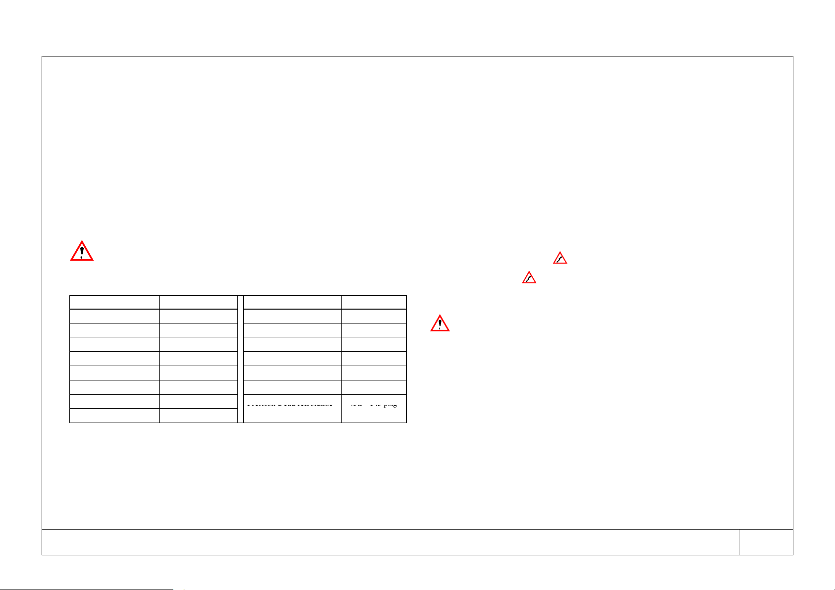
j) Pour les modèles à refroidissement liquide
RECOMMANDATIONS SUR LA QUALITÉ DE L’EAU
La qualité de l’eau doit satisfaire aux conditions suivantes:
Paramètre Concentration Paramètre Concentration
Indice de Langelier 0 --- 1 Fer (Fe) <0,2 ppm
pH 7 . 5 --- 9 Nitrate (NO
3
)<2 ppm
Sulfate (SO
42 ---
)<50 ppm Alcalinité (HCO
3---
)70---300 ppm
Conductivité électrique 10---500µS/cm Sulfure d’hydrogène (H
2
S) <0.05 ppm
Ammoniac (NH
3
)<1 ppm CO
2
libre <5 ppm
Chlorure (Cl
---
)<50 ppm Aluminium (Al) <0.2 ppm
Dureté totale 70---150 ppm CaCO
3
Pression d’eau refroidisse- 43.5---145 psig
Oxygène <0.1 ppm
P
r
e
s
s
i
o
n
d
e
a
u
r
e
f
r
o
i
d
i
s
s
e
ment condenseur
4
3
.
5
1
4
5
p
s
i
g
(3---10 barg)
k) Toujours installer une ligne de by---pass et des vannes d’interception (fournies en
option SR-250 -- SR-500)afinquelesopérationsd’entretienouderéglagepuis-
sent être effectuées sans qu’il soit nécessaire de couper le débit d’air comprimé
à l’utilisateur.
l) Reliercorrectementlesécheurauxraccordsd’entréeetdesortiedel’air.Sile
réseau d’air comprimé est sujet à des vibrations, effectuer le raccordement à
l’aide de tuyaux flexibles. Si le réseau est soumis à de fortes pulsations, effectuer
le branchement avec des amortisseurs de pulsations.
m) Ne pas relier en circuit fermé des évacuations de condensats en commun avec
d’autres lignes de purge pressurisées.
Visualiser l’évacuation des condensats pour vérifier leur écoulement correct.
Raccorderletuyaudeconduitedelacondensationdefaçonàcequeleniveau
sonore soit le plus faible possible durant le drainage.
Veiller à ce que toute la condensation soit éliminée soigneusement, dans le re-
spect des normes locales en matière de protection de l’environnement.
n) L’air ambiant autour du sécheur et du compresseur ne devrait pas contenir de
contaminants solides ou gazeux. Se souvenir que tout gaz comprimé et condensé
pourrait produire des acides ou des produits chimiques susceptibles d’endom-
mager le compresseur ou les composants internes du sécheur. Faire attention au
soufre, à l’ammoniaque, au chlore et à l’installation en milieu marin. Pour tous
conseils ou assistance, contacter le constructeur.
2.1 Raccordement électrique (voir Fig. 5 / Fig. 10)
Utiliser un câble conforme aux réglementations en vigueur dans le pays d’installa-
tion (sur les bornes “L1 et L2 ” pourles machinesmonophasées, et sur les bornes
“ L 1 --- L 2 --- L 3 --- G N D ” pour les machines triphasées), prélevé dans la boîte de
dérivation, ayant une section minimale: (voir schéma électrique Fig. 10 relatif à la
machine).
Installez un disjoncteur de courant à la terre et par surintensité en amont de
l’installation (IDn = 0,3A) avec un écart de 0.12 inch (3 mm) entre les contacts
lorsqu’il est ouvert (reportez---vous également à la législation locale).
2.2 Raccordement purge condensats
a) Le purgeur est déjà installé sur la machine (voir manuel à part).
b) raccorder le tuyau d’évacuation de la condensation au système de drainage.
c) Toute opération d’entretien doit être effectuée par un technicien spécialisé.
N.B.: Le sécheur est fourni soit avec un drain temporisé, soit avec un drain à
contrôleur électronique de niveau. Pour les détails spécifiques relatifs au tuyau
d’évacuation de la condensation, consulter le manuel fourni avec le sécheur.

16
Code: 02250145-- 604 SR-- 250 --- SR-- 3000
Français
3 Mise en marche et fonctionnement
N.B.: Pour obtenir les instructions spécifiques au panneau de commande, consultez
le Chapitre 4.
3.1 Contrôles préliminaires
Avantdemettrelesécheurenmarche,s’assurerque:
a) Les vannes d’entrée air sont fermées et qu’il n’y a pas de débit d’air à travers le
sécheur.
b) La tension de l’alimentation fournie au sécheur est correcte.
c) Le sécheur est installé conformément aux instructions d’installation du Chap. 2.
3.2 Miseenmarchedel’installation
a) Le sécheur est démarré en utilisant l’interrupteur principal.
b) Démarrer l’unité avant démarrage du compresseur d’air.
c) Tourner le sectionneur jaune---rouge général “QS” pour le mettre sur “On”. La
LED jaune de contrôle sous tension.
d) Attendre environ 5 minutes afin que le sécheur atteigne les
températures/pressions de fonctionnement.
e) Ouvrir lentement la vanne d’entrée air pour pressuriser le sécheur.
f) Ouvrir lentement la vanne de sortie air. Le sécheur est maintenant en train de
sécher.
g) Le sécheur devra rester en marche pendant toute la période de fonctionnement
du compresseur d’air.
h) Il est très important de contrôler le sens de rotation des compresseurs
rotatifs. S’ils sont alimentés par un mauvais déphasage, ils tourneront
dans le sens contraire de la marche normale. Si tel est le cas, ils fonction-
nent bruyamment et risquent d’être endommagés. INVERSEZ IMME-
DIATEMENT LES PHASES.
Assurez---vous que la pression affichée sur la jauge (LP), qui se trouve
surlafaceavant,diminue.
3.3 Arrêt de l’installation
a) Le sécheur est arrêté en utilisant l’interrupteur principal.
b) Arrêter l’installation 2 minutes après avoir arrêté le compresseur d’air ou en tout
cas après avoir interrompu le débit d’air à travers le sécheur.
Évitez de permettre l’entrée d’air comprimé dans le séchoir lorsque
celui---ciestéteintoudansunétatd’alarmearrêtantlecompresseurde
réfrigération.
3.4 Fonctionnement
SLe sécheur fonctionne de façon entièrement automatique : il est réglé en usine
sur un point de rosée de 37˚F(3˚C) (ISO 7183, 2
ème
partie). Par conséquent, au-
cun réglage n’est nécessaire.
SNe pas dépasser les limites de projet del’unité ; by---passer les excès de débit d’air.
Vérifier le choix et/ou l’installation de l’unité.
SPour obtenir les meilleures performances de l’installation, il est nécessaire
d’effectuer l’entretien périodique décrit au CHAPITRE 5.
SPour ces sécheurs, le niveau de pression sonore est inférieur à 70 dB(A) relevés
à 40 inch (1 m) de distance de la machine en champ libre.
SLa Fig. 6 montre les circuits de réfrigération et pneumatique du sécheur.

17
Code: 02250145-- 604 SR-- 250 --- SR-- 3000
Français
4 Le panneau de commande
4.1 Panneau frontal
Toutes les opérations sont effectuées et affichées sur le panneau frontal du contrôle
électronique de la façon suivante:
afficheur
Afficheur
SLa mise sous tension de l’unité permet de visualiser l’unité de mesure (˚Cou˚F)
de la température indiquée.
SDurant le fonctionnement normal, la température visualisée est celle du point de
rosée (T0).
SLorsque le sécheur est en état d’alarme, le code d’alarme s’affiche.
SSi l’utilisateur est dansle RAPPORT D’ETAT (STATUS REPORT), il indique les
événements les plus récents qui se sont produits sur le sécheur.
SEn cas d’avis de point de rosée élevé, la valeur de la température et le code d’avis
Hd s’affichent tour à tour.
SEn cas d’alarme point de rosée bas, la valeur de la température et le code d’alarme
Ld s’affichent tour à tour.
Clavier
on off
marche---arrêt sécheur
Les fonctions disponibles lorsque le sécheur est sur off sont les suivantes:
a) Configuration de la dernière DATE D’ENTRETIEN;
b) introduction et réglage des paramètres de fonctionnement;
c) lecture du RAPPORT D’ETAT.
reset
Son enfoncement lors d’un état d’alarme en cours permet de remettre à
zéro l’alarme ou le signal au moment de l’élimination de la cause.
Egalement utilisé pour les fonctions suivantes:
a) sélection de la plage de températures;
b) remettre à zéro la mémoire de l’alarme;
c) dernière date d’entretien;
d) lecture du compteur horaire du compresseur;
report
On l’utilise également pour accéder à l’ÉTAT RAPPORT.
LEDs
a
l
a
r
m
(
r
o
u
g
e
)
ALARME
LED rouge allumée Une ou plusieurs alarmes sont
actives.
a
l
arm
(
rouge
)
AVI S
LED rouge clignotante Un ou plusieurs avis sont ac-
tifs.
off remote (jaune) OFF A DISTANCE
LED jaune allumée Le sécheur est en état d’arrêt
depuis le contrôle à distance.
dryer on (vert) ON
LED verte allumée Le sécheur est en marche.
power on (jaune) LIGNE
LED jaune allumée Le sécheur est sous tension.

18
Code: 02250145-- 604 SR-- 250 --- SR-- 3000
Français
4.2 Fonctionnement
a) Mise en marche et arrêt
Tourner le sectionneur général sur I (LED jaune “power on” allumée). Il est pos-
sibledemettreenmarchel’unitéenappuyantsurlatoucheon/off,avecunretard
de 6 secondes. Durant ce retard, la LED verte “dryer on” clignote.
b) On/off à distance
Il est possible d’arrêter l’unité par commande à distance (l’on/off à distance et
le branchement correspondant sont à la charge du client) après un temps de
fonctionnement de 5 minutes. Le fonctionnement de l’unité suivra l’état du con-
tact à distance (voir bornes 16, 2).
contact ouvert = unité sur off;
contact fermé = unité sur on.
En appuyant sur le bouton on/off, situé sur le tableau de contrôle, lorsque l’unité
est en mouvement, celle---ci va en état d’ARRÊT (indépendemment du signal à
distance).
c) Contact de signalisation/alarme (hors tension).
Le fonctionnement de la sortie numérique de signalisation ou d’alarme (bornes
32, 33 sur le schéma électrique), utilisable sous une tension maximale de 250V
et un courant maximal de 1A, dépend du réglage du paramètre “rL” (polarités
relais alarme), selon le schéma suivant:
Paramètre rL État du contact Signification
Fermé Aucune alarme.
on Ouvert Alarme/signalisation en cours ou
sécheur hors tension.
o
F
Fermé Alarme/Signalisation en cours.
o
F
Ouvert Aucune alarme ou sécheur hors tension.
d) Réglage seuil de signalisation haute température point de rosée
Il existe une fonction de signalisation de haute température du point de rosée.
Si la température du point de rosée reste, durant le fonctionnement, plus de trois
minutes au---delà du seuil d’alarme (paramètre Ht), l’anomalie est signalée par
l’activation du relais d’alarme. La signalisation disparaît automatiquement lor-
sque la température du point de rosée atteint une valeur inférieure de 3.6˚F
(2˚C) par rapport au seuil de signalisation programmé.
e) Fonction d’ “ÉCONOMIE ÉNERGÉTIQUE” (CM)
La fonction CM permet de maintenir la température de l’échangeur à une valeur
comprise entre tA (minimale) et tb (maximale) au moyen de la mise en marche
et de l’arrêt du compresseur frigorifique.
Il n’est possible d’activer la fonction CM que lorsque le paramètre tC est pro-
grammé sur “on” durant l’activation du off à distance (voir tableau).
Contact off à
distance État du
paramètre “tC” Signification
Contact ouvert tC = oF Compresseur frigorifique éteint en
permanence.
C
o
n
t
a
c
t
o
u
v
e
r
t
tC = on CM = activée.
C
o
n
t
a
c
t
f
e
r
m
é
tC = oF Compresseur frigorifique en fonction-
C
ontact
f
erm
é
tC = on
C
o
m
p
r
e
s
s
e
u
r
f
r
i
g
o
r
i
f
i
q
u
e
e
n
f
o
n
c
t
i
o
n
nement permanent.
S
S
S
StA: température d’arrêt du compresseur frigorifique;
S
S
S
Stb: températuredemiseenmarcheducompresseurfrigorifique;
S
S
S
StC: activation/désactivation de la modalité masse froide comme l’indique le
tableau.
4.3 Fonctions générales
GESTION RAPPORT et COMPTEUR D’HEURES
N.B.: L’option RAPPORT/COMPTEUR D’HEURES n’est active que lorsque le
sécheur est sous tension (“power on”).
L’enfoncement du bouton de reset/report pendant 6 secondes permet d’accéder à la
fonction Remise à zéro/Rapport (l’écran affiche le sigle “rE”) où sont visualisées en
séquence les 8 dernières alarmes et/ou signalisations s’étant activées ainsi que les
heures de fonctionnement du compresseur frigorifique.
a) L’enfoncement de la touche permet de faire défiler les 8 derniers évènements
par ordre chronologique:
1 --- --- --- d e r n i e r é v è ne m e n t --- --- ---
2 --- --- --- a v a n t --- d e r n i e r é v è ne m e n t --- --- ---
3 --- --- --- --- --- --- --- --- --- --- --- --- --- --- --- ---
8 --- --- --- h u i t i è m e é v è ne m e n t --- --- ---
b) L’enfoncement de la touche reset/report permet d’afficher les heures de fonction-
nement du compresseur frigorifique.
Le nombre d’heures de travail enregistrées est de 99.999. La visualisation des
heures de travail apparaît sur trois pages---écrans différentes à intervalles de
deux secondes:
--- Première page-- écran:
visualisation des MILLIERS et clignotement simultané de la LED rouge
alarm.

19
Code: 02250145-- 604 SR-- 250 --- SR-- 3000
Français
--- Deuxième page-- écran:
visualisation des CENTAINES et clignotement simultané de la LED jaune off
remote.
--- Tr oi sième p ag e -- écran:
visualisation des DIZAINES et clignotement simultané de la LED verte dryer
on.
Il sera ainsi possible d’obtenir la composition des heures de travail.
Pour sortir de la visualisation des heures de travail, appuyer de nouveau sur la touche
reset/report.
CONFIGURATION DES PARAMÈTRES DE FONCTIONNEMENT
Pour pouvoir configurer les paramètres de fonctionnement, procéder de la manière
suivante : mettre l’installation hors tension (sectionneur général sur 0).
1) Tourner le sectionneur général de 0 à I tout en enfonçant le bouton on/off.
2) L’écran affiche “CC”.
3) Appuyer sur la touche on/off; l’écran affiche alternativement le message “CF” et
l’unitédemesureprogramméedelatempérature.Appuyer sur la touche reset
pour modifier l’unité de mesure (˚C, ˚F).
4) Appuyer sur la touche on/off pour accéder au réglage du paramètre “tA” (le mes-
sage “tA” et la valeur programmée correspondante s’affichent alternativement);
appuyer sur la touche reset/report pour configurer la température souhaitée
[valeur pré---établie 43˚F(6˚C)]. Chaque pression de la touche augmentera la
tA de +1˚C/1˚F.
5) Appuyersur la touche on/off pour passer au réglage duparamètre “tb” (le message
“tb” et la valeur programmée correspondante s’affichent alternativement);
appuyer sur la touche reset pour programmer la température maximale souhaitée
[valeur pré---établie 50˚F(10˚C)].
6) Appuyersurlatoucheon/offpouraccéderauréglageduparamètre“tC”(lemessage
“tC” et la valeur programmée correspondante s’affichent alternativement). Le
réglageest effectuéselonlesindicationsdupoint précédent;appuyersur la touche
reset pour sélectionner la valeur souhaitée (on ou oF) [valeur pré---établie oF].
7) Appuyer sur la touche on/off pour sélectionner le seuil de la signalisation de haute
température du point de rosée (le message “Ht” et la valeur programmée corre-
spondante s’affichent alternativement); appuyer sur la touche reset pour régler
le seuil de signalisation [valeur pré---établie 59˚F(15˚C)]. Pour le réglage, voir
point 4).
8) Appuyer sur la touche on/off. pour afficher alternativement le message “Id” et la
valeur programmée correspondante); appuyer sur la touche on/off.
9) Appuyer sur la touche on/off pour sélectionner la modalité de fonctionnement du
relais d’alarme (voir point c) para. 4.2); appuyer sur la touche reset pour modifier
la valeur du paramètre [valeur pré---établie on = relais activé].
10)Appuyer sur la toucheon/off pour quitter les configurations et mémoriser tous les
paramètres configurés.
11)Il est à ce point possible de mettre le sécheur en marche en appuyant sur on/off.
N.B. : Un réglage tC configuré sur “on” activera la fonction “CM”.
CONFIGURATION DE LA DATE DU DERNIER ENTRETIEN
1) Tourner le sectionneur général de 0 à I tout en enfonçant le bouton reset.
2) Vous verrez le code “CL”.
3) Appuyer sur la touche on/off pour accéder à la configuration de la date du dernier
entretien. L’écran affichera tour à tour le message “AA”, indiquant l’ “Année”, et
l’année du dernier entretien programmé. Appuyer sur la touche reset pour faire
avancer la valeur visualisée.
4) Appuyer sur la touche pour visualiser tour à tour le sigle “MM”, indiquant le
“Mois”, et le mois programmé. Appuyer sur la touche reset pour faire avancer la
valeur visualisée.
5) Appuyer sur la touche pour visualiser tout à tour le sigle “GG”, indiquant le
“Jour”, et le jour programmé. Appuyer sur la touche reset pour faire avancer la
valeur visualisée.
6) Appuyer sur la touche on/off pour enregistrer les valeurs programmées.
4.4 Alarmes et Signalisation
H P --- A la r m e d e h a u te p r e s s i o n
L’activation du pressostat dehaute pression provoque l’arrêt ducompresseurfrigori-
fique. L’écran affiche tour à tour les codes d’alarme HP et PI. L’élimination de la
cause (avant de continuer, suivre la mise sous sécurité de l’installation selon les indi-
cations du para. 3.3), et l’enfoncement de la touche reset provoquent la désactivation
de l’alarme.
This manual suits for next models
12
Table of contents
Languages:
Other Sullair Dryer manuals

Sullair
Sullair RH Series Troubleshooting guide

Sullair
Sullair SAR 180 User manual

Sullair
Sullair SRC Series User manual

Sullair
Sullair SRV-250 User manual

Sullair
Sullair 02250201-297 R01 User manual

Sullair
Sullair SRL Series User manual

Sullair
Sullair SAR 003 User manual

Sullair
Sullair DEX Series Troubleshooting guide

Sullair
Sullair DMD Series Troubleshooting guide

Sullair
Sullair SRL-1200 User manual


