Sulzer ABS RW 480 User manual

www.sulzer.com
EU 6184-E
Submersible Mixer Type ABS RW 480
6006184 09.2018
Einbau- und Betriebsanleitung.......................................2 Inbouwhandleiding en gebruiksaanwijzing........................... 29
Installation and Operating Instructions ..........................5 Instrução de montagem e de utilização ............................... 32
Instructions de montage et d‘utilisation .........................8 Monterings- og bruksanvisning ............................................35
Istruzioni di montaggio e d‘uso.................................. ...11 Instrukcjamontażuiobsługi .................................................38
Instrucciones de Instalación y Funcionamiento...........14 Paigaldus- ja kasutusjuhend................................................ .41
Monterings- och bruksanvisning ..................................17 Beépítési és üzemeltetési útmutató......................................44
Monterings- og betjeningsvejledning ......................... .20 Montážníaprovoznípokyny................................................ .47
Asennus - ja käyttöohje.............................................. .23 Ръководствозамонтажиексплоатация .........................50
ΟδηγίεςΕγκατάστασηςκαιΛειτουργίας......................26 Instrucţiunidemontajşiutilizare ..........................................53
de nl
en pt
fr no
it pl
es et
sv hu
da cs
fi bg
el ro

2
1 Allgemeines
Grundsätzlich ist die Einbau- und Betriebsanleitung mit Art.-Nr. 6006183 / 6005672 (ABS Tauchmotorrührwerke RW) in großen Teilen
auch für das RW 480 gültig. Dies gilt auch für den sachgemäßen Anschluss und den sicheren Betrieb der Ex-Ausführung des
RW 480. Gleiches gilt für die Sicherheitshinweise. Diese sind in dem separaten Heft mit der Art.-Nr. 1 597 0799 enthalten und sind vor
der Installation und Inbetriebnahme sorgfältig zu studieren!
In dieser „Zusatz“-Einbau- und Betriebsanleitung für das ABS Tauchmotorrührwerk RW 480 sind daher nur Querverweise bzw. die
abweichenden,zusätzlichenundproduktspezischenInformationenenthalten.
1.1 - 1.3 Einführung; Bestimmungsgemäße Verwendung; Einsatzgrenzen
Siehe Kapitel 1.1 - 1.3 der Einbau- und Betriebsanleitung 6006183 / 6005672.
1.4 Einsatzbereiche
DasTauchmotorrührwerkRW480dientzumMischen,RührenundUmwälzenvonzähen,feststohaltigenFluideninKläranlagen,inderIndustrieundin
der Landwirtschaft. Es ist besonders für die speziellen Anforderungen bei der Homogenisierung von Schlamm und Kofermenten ausgelegt.
1.5 Typenschlüssel
Siehe Kapitel 1.5 der Einbau- und Betriebsanleitung 6006183 / 6005672. *Propellertyp = 2-Blatt-Spezialpropeller für Schlamm und Kofermente.
1.6 Technische Daten
Siehe Kapitel 1.6 der Einbau- und Betriebsanleitung 6006183 / 6005672.
1.6.1 Technische Daten RW 480, 50 Hz
Rührwerkstyp
Propeller-
durchmesser
Drehzahl /
Getriebeunter-
setzung
Motortyp
Nennleistungs-
aufnahme P1
Motornennlei-
stung P2
Startart: Direkt
(D.O.L)
Startart: Stern/
Dreieck
Nennstrom bei
400 V
Anlaufstrom
bei 400 V
Kabeltyp** (Ex-
und Standard)
Temperatu-
rüberwachung
Dichtungsü-
berwachung
Ex dII BT4
Führungsrohr
□ 100
Gesamtge-
wicht
[mm] [1/min] [kW] [kW] [A] [A] [kg]
RW 4811 480 446/3,3 A 75/4 8,66 7,5 ●14,84 93,9 2● ● ○ ● 163
RW 4812 480 467/3,1 A 75/4 8,66 7,5 ●14,84 93,9 2● ● ○ ● 163
RW 4813 480 493/3,0 A 75/4 8,66 7,5 ●14,84 93,9 2● ● ○ ● 163
RW 4814 480 517/2,8 A 110/4 13,0 11,0 ●21,85 103,4 2● ● ○ ● 169
RW 4815 480 554/2,6 A 110/4 13,0 11,0 ●21,85 103,4 2● ● ○ ● 169
1.6.2 Technische Daten RW 480, 60 Hz
RW 4811 480 503/3,5 A 90/4 10,2 9,0 ●15,32 103 2● ● ● 163
RW 4812 480 535/3,3 A 90/4 10,2 9,0 ●15,32 103 2● ● ● 163
RW 4813 480 561/3,1 A 130/4 15,0 13,0 ●21,88 119,9 2● ● ● 169
P1= Leistungsaufnahme; P2=Leistungsabgabe;●=Standard;○=Option;**Kabeltyp:10mKabelmitfreiemKabelendesindStandardlieferumfang:2=1x10Gx1.5
1.7 Abmessungen und Gewichte
Siehe Kapitel 1.7 der Einbau- und Betriebsanleitung 6006183 / 6005672.
1.7.1 Baumaße RW 480
1031
[40.6]
94
[3.7]
405
[15.9]
1127
[44.4]
min. 190
[min. 7.5]
405
[15.9]
□ 100
[□ 4]
ø 482
[19 dia]
min. 50
[min. 2]
ø 482
[19 dia]
109.6
[4.3]
ø 226
[8.9 dia]
312
[12.3]
47.5
[1.9]
□ 100
[□ 4]
mm
inch
min. 800
[min. 31.5 dia]
0551-0042
Bild 1 Baumaße RW 480
DE 6184-E
...
460 V
...
460 V

3
1.8 Typenschild
Siehe Kapitel 1.8 der Einbau- und Betriebsanleitung 6006183 / 6005672.
2 - 3 Sicherheit; Transport und Lagerung
Siehe Kapitel 2 - 3 der Einbau- und Betriebsanleitung 6006183 / 6005672.
4 Produktbeschreibung
4.1 Beschreibung allgemein
Siehe Kapitel 4.1 der Einbau- und Betriebsanleitung 6006183 / 6005672.
4.2 Konstruktiver Aufbau RW 480
10
962
3
81
12 11
5
7
4
0551-0043
Legende
1 Halterung
2 Kabeleinführung
3 Anschlußraum
4 Propellerwelle
5 Motorwicklung
6 Halterung mit Schäkel
7 Motorgehäuse
8 Gleitringdichtung
9 Propellernabe / Propeller
10 Getriebe
11 Welleneinheit mit Rotor und Lagern
12 SD - Ring
Bild 2 RW 480
4.3 Betrieb an Frequenzumrichtern
Siehe Kapitel 4.5 der Einbau- und Betriebsanleitung 6006183 / 6005672.
5 Installation
Siehe Kapitel 5 der Einbau- und Betriebsanleitung 6006183 / 6005672.
5.1 Installation RW 480
Siehe Kapitel 5.1 der Einbau- und Betriebsanleitung 6006183 / 6005672.
5.2 Propellermontage RW 480
Konstruktionsbedingt unterscheidet sich die Propellerbefestigung von den anderen Aggregaten der RW/RCP bzw SB-KA Baureihe. Der
Propeller der RW 480 ist mit einem gekapselten Spannsatz befestigt.
1
2
3
4
5
67
0551-0044
Legende
1 Zylinderschraube
2 Propellerscheibe
3 Sicherungsscheiben
4 O-Ring (Zylinderschraube)
5 O-Ring (Propellerscheibe)
6 Spannsatz
7 O-Ring (Nabe)
Bild 3 Propellermontage/-demontage
Demontage
• Zylinderschraube (3/1) mit Sicherungsscheiben (3/3), O-Ring (3/4), Propellerscheibe (3/2) und O-Ring (3/5) demontieren.
• Schrauben des Spannsatzes (3/6) lösen und Propeller zusammen mit dem Spannsatz abziehen. O-Ring (3/7) aus der Nut entfernen.
DE 6184-E

4
Montage
• Welle und Nabe reinigen. Neuen O-Ring (3/7) in die Nut der Nabe einsetzen, Welle und Spannsatz (3/6) leicht ölen.
ACHTUNG Keine Öle verwenden, die Molybdän-Schwefelkohlensto enthalten!
• Schraube des Spannsatzes erst über Kreuz leicht anziehen.
• Schrauben des Spannsatzes über Kreuz mit 16 Nm festziehen. Anschließend Anzugsmoment im Uhrzeigersinn umlaufend überprüfen.
• Sicherungsscheiben (3/3) zusammen mit O-Ring (3/4), Propellerscheibe (3/2) und O-Ring (3/5) auf Zylinderschraube (3/1) stecken und
mit 17 Nm anziehen.
5.3 Anzugsmomente
Siehe Kapitel 5.3 der Einbau- und Betriebsanleitung 6006183 / 6005672.
5.4 Installationsbeispiel RW 480
Für diese Installation wird empfohlen, die geschlossene Halterung zu verwenden.
4
7
6
2
3
5
1
0551-0045
Legende
1 Hebegalgen
2 Oberer Haltebock
3 Halterung geschlossen
4 Bodenlager
5 Sicherheitsklemmanschlag
6 Drehbares Vierkantleitrohr
7 Abspannklemme mit Kabelhaken
Bild 4 Installationsbeispiel RW 480
5.5 Halterungen RW/SB-KA
Siehe Kapitel 5.5 der Einbau- und Betriebsanleitung 6006183 / 6005672.
5.6 Führungsrohrlängen (Vierkantleitrohr) RW/SB-KA
Siehe Kapitel 5.6 der Einbau- und Betriebsanleitung 6006183 / 6005672. RW 480 ≙RW 900.
5.7 Elektrischer Anschluß
Siehe Kapitel 5.8 der Einbau- und Betriebsanleitung 6006183 / 6005672. Siehe Bild 32. Kapitel 5.8.3 ist nicht relevant für RW 480.
6 - 7 Inbetriebnahme; Wartung
Siehe Kapitel 6 - 7 der Einbau- und Betriebsanleitung 6006183 / 6005672.
DE 6184-E

5
1 General
Basically the main parts of the installation and operating instructions with part no. 6006183 / 6005672 (ABS submersible mixer RW) are also
valid for RW 480. This also applies if the RW 480 model Ex is connected correctly and operated in safe mode. Same applies for the Safety
instructions. These are included in the separate booklet 1 597 0799 and have to be studied carefully before installation and commisioning!
These additional installation and operating instructions for ABS submersible mixer RW 480 contain only cross-references e.g. the
diering,additionalandproduct-specicinformation.
1.1 - 1.3 Introduction; Correct usage of the product; Application restrictions
See chapter 1.1 - 1.3 of the Installation and Operating Instructions 6006183 / 6005672.
1.4 Application areas
ThesubmersiblemixerRW480isusedformixing,stirringandagitatingofviscousuidscontainingsolidsinsewagetreatmentplants,
industry,andagriculture.Itisspecicallydesignedforthemajormixingfuctionsduringhomogenizationofsludgeandcoenzymes.
1.5 Identication code
See chapter 1.5 of the Installation and Operating Instructions 6006183 / 6005672. *Propeller type = 2-blade special propeller for sludge
and coenzymes.
1.6 Technical data
See chapter 1.6 of the Installation and Operating Instructions 6006183 / 6005672.
1.6.1 Technical data RW 480, 50 Hz
Mixer type
Propeller dia-
meter
Speed / Gear
ratio
Motor type
Rated power
input P1
Rated power
output P2
Starting: Direct
(D.O.L)
Starting: Star/
Delta
Rated current
at 400 V
Starting cur-
rent at 400 V
Cable type**
(Ex- and standard)
Temperature
monitoring
Seal monito-
ring
Ex dII BT4
Guide tube □
100
Total weight
[mm] [1/min] [kW] [kW] [A] [A] [kg]
RW 4811 480 446/3.3 A 75/4 8.66 7. 5 ●14.84 93.9 2● ● ○ ● 163
RW 4812 480 467/3.1 A 75/4 8.66 7.5 ●14.84 93.9 2● ● ○ ● 163
RW 4813 480 493/3.0 A 75/4 8.66 7.5 ●14.84 93.9 2● ● ○ ● 163
RW 4814 480 517/2.8 A 110/4 13.0 11.0 ●21.85 103.4 2● ● ○ ● 169
RW 4815 480 554/2.6 A 110/4 13.0 11.0 ●21.85 103.4 2● ● ○ ● 169
1.6.2 Technical data RW 480, 60 Hz
RW 4811 480 503/3.5 A 90/4 10.2 9.0 ●15.32 103 2● ● ● 163
RW 4812 480 535/3.3 A 90/4 10.2 9.0 ●15.32 103 2● ● ● 163
RW 4813 480 561/3.1 A 130/4 15.0 13.0 ●21.88 119.9 2● ● ● 169
P1=Power input; P2=Poweroutput;●=Standard;○=Option;**Cabletype:10mcablewithfreeendsasstandard:2=1x10Gx1.5
1.7 Dimensions and weights
See chapter 1.7 of the Installation and Operating Instructions 6006183 / 6005672.
1.7.1 Dimensions RW 480
1031
[40.6]
94
[3.7]
405
[15.9]
1127
[44.4]
min. 190
[min. 7.5]
405
[15.9]
□ 100
[□ 4]
ø 482
[19 dia]
min. 50
[min. 2]
ø 482
[19 dia]
109.6
[4.3]
ø 226
[8.9 dia]
312
[12.3]
47.5
[1.9]
□ 100
[□ 4]
mm
inch
min. 800
[min. 31.5 dia]
0551-0042
Figure 1 Dimensions RW 480
EN 6184-E
...
460 V
...
460 V

6
1.8 Nameplate
See chapter 1.8 of the Installation and Operating Instructions 6006183 / 6005672.
2 - 3 Safety; Transport and storage
See chapter 2 - 3 of the Installation and Operating Instructions 6006183 / 6005672.
4 Product description
4.1 General description
See chapter 4.1 of the Installation and Operating Instructions 6006183 / 6005672.
4.2 Structural design RW 480
10
962
3
81
12 11
5
7
4
0551-0043
Legend
1 Bracket
2 Cable inlet
3 Connection chamber
4 Propeller shaft
5 Stator
6 Bracket with shackle
7 Motor housing
8 Mechanical seal
9 Propeller boss / Propeller
10 Gear
11 Shaft unit with rotor and bearings
12 SD - ring
Figure 2 RW 480
4.3 Operation with frequency inverters
See chapter 4.5 of the Installation and Operating Instructions 6006183 / 6005672.
5 Installation
See chapter 5 of the Installation and Operating Instructions 6006183 / 6005672.
5.1 Installation RW 480
See chapter 5.1 of the Installation and Operating Instructions 6006183 / 6005672.
5.2 Propeller assembly RW 480
ThepropellerxingdiersfromallotherunitsofRW/RCPandSB-KAseriesduetodesign.ThepropelleroftheRW480isxedwithan
encapsulated clamping element.
1
2
3
4
5
67
0551-0044
Legend
1 Socket head screw
2 Propeller washer
3 Lock washers
4 O-ring (socket head screw)
5 O-ring (oropeller washer)
6 Clamping element
7 O-ring (boss)
Figure 3 Propeller assembly / dismantling
Dismantling
• Dismantle socket head screw (3/1) with lock washers (3/3), o-ring (3/4), propeller washer (3/2) and o-ring (3/5).
EN 6184-E

7
• Loosen the screws of the clamping element (3/6) and withdraw the propeller together with the clamping element. Remove o-ring (3/7)
out of groove.
Assembly
• Clean carefully the shaft and boss. Insert new o-ring (3/7) into the boss groove and lightly oil the shaft and clamping element (3/6).
ATTENTION Do not use any products containing molybdenum disulphide!
• Evenly / slightly tighten the screws of the clamping element in a crosswise sequence.
• Finally tighten fully going from side to side with a tightening torque of 16 Nm. Then check tightening torque in a crosswise sequence.
• Put lock washers (3/3) together with o-ring (3/4), propeller washer (3/2) and o-ring (3/5) on socket head screw (3/1) and tighten with
17 Nm.
5.3 Tightening torque
See chapter 5.3 of the Installation and Operating Instructions 6006183 / 6005672.
5.4 Installation example RW 480
We recommend that the closed bracket be used for this type of installation
4
7
6
2
3
5
1
0551-0045
Legend
1 Hoist with winch and rope
2 Upper bracket with locking plate
3 Closed bracket
4 Bottom plate
5 Safety stop clamp
6 Swivelling square guide tube
7 Cable clamp with cable hook
Figure 4 Installation example RW 480
5.5 Brackets RW/SB-KA
See chapter 5.5 of the Installation and Operating Instructions 6006183 / 6005672.
5.6 Guide tube lengths (square tube) RW/SB-KA
See chapter 5.6 of the Installation and Operating Instructions 6006183 / 6005672. RW 480 ≙RW 900.
5.7 Electrical connection
See chapter 5.8 of the Installation and Operating Instructions 6006183 / 6005672. See gure 32. Chapter 5.8.3 is not relevant to RW 480.
6 - 7 Commisioning; Maintenance
See chapter 6 - 7 of the Installation and Operating Instructions 6006183 / 6005672.
EN 6184-E

8
1 Généralités
De manière générale, la notice de montage et d'utilisation, réf. 6006183 / 6005672 (ABS agitateurs à moteur submersible RW) est égale-
ment valable pour le modèle RW 480. Ceci vaut également pour le raccordement conforme et le fonctionnement sûr du modèle Ex du
RW 480. Il en est de même pour les consignes de sécurité.Celles-cigurentdansundocumentséparé,réf.15970799,etdoiventêtre
soigneusement étudiées avant l'installation et la mise en service !
Cette notice de montage et d'utilisation « supplémentaire » pour l'agitateur à moteur submersible ABS RW 480 comprend en
outreuniquementdesréférencescroiséesoudesinformationsdérivées,supplémentairesetspéciquesauproduit.
1.1 - 1.3 Introduction; Utilisation conforme; Limites d’utilisation des unités
Voir Chapitre 1.1 - 1.3 de l’Instructions de montage et d'utilisation 6006183 / 6005672.
1.4 Domaines d‘application
L'agitateuràmoteursubmersibleRW480sertàmélanger,agiteretbrasserlesuidesvisqueuxetsolidesdanslesstationsd'épuration,
dans l'industrie et dans l'agriculture. Il a été spécialement conçu pour les exigences spéciales en matière d'homogénéisation de la boue et
des co-ferments/co-substrats.
1.5 Codes de types
Voir Chapitre 1.5 de l’Instructions de montage et d'utilisation 6006183 / 6005672. *Type d‘hélice = Hélice spéciale 2-pales pour la boue et
les co-ferments/co-substrats.
1.6 Caractéristiques techniques
Voir Chapitre 1.6 de l’Instructions de montage et d'utilisation 6006183 / 6005672.
1.6.1 Caractéristiques techniques RW 480, 50 Hz
Type
d‘agitateur
Diamètre
d’hélice
Vitesse / Ré-
ducteur
Type de mo-
teur
Puissance nomi-
nale absorbée
P1
Puissance nomi-
nale du moteur P2
Type de démarra-
ge : direct (D.O.L)
Type de démarrage
: étoile / triangle
Courant nomi-
nal à 400 V
Courant de dé-
marrage à 400 V
Type de câble**
(Ex-et standard)
Contrôle de
température
Contrôle de
l’étanchéité
Ex dII BT4
Tube de guida-
ge □ 100
Poids total
[mm] [1/min] [kW] [kW] [A] [A] [kg]
RW 4811 480 446/3,3 A 75/4 8,66 7,5 ●14,84 93,9 2● ● ○ ● 163
RW 4812 480 467/3,1 A 75/4 8,66 7,5 ●14,84 93,9 2● ● ○ ● 163
RW 4813 480 493/3,0 A 75/4 8,66 7,5 ●14,84 93,9 2● ● ○ ● 163
RW 4814 480 517/2,8 A 110/4 13,0 11,0 ●21,85 103,4 2● ● ○ ● 169
RW 4815 480 554/2,6 A 110/4 13,0 11,0 ●21,85 103,4 2● ● ○ ● 169
1.6.2 Caractéristiques techniques RW 480, 60 Hz
RW 4811 480 503/3,5 A 90/4 10,2 9,0 ●15,32 103 2● ● ● 163
RW 4812 480 535/3,3 A 90/4 10,2 9,0 ●15,32 103 2● ● ● 163
RW 4813 480 561/3,1 A 130/4 15,0 13,0 ●21,88 119,9 2● ● ● 169
P1=Puissance absorbée; P2=Puissancedébitée;●=Standard;○=Option;**Typedecâble:10mdecâbleavecextrémitélibrefontpartiedelafourniturestandard:2=1x10Gx1.5
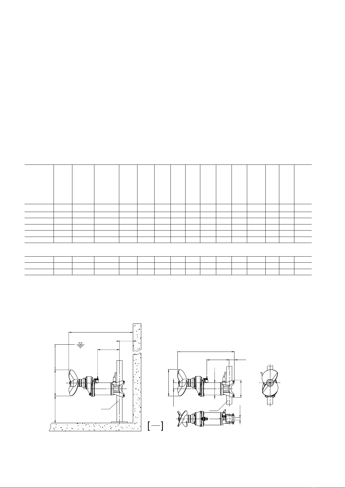
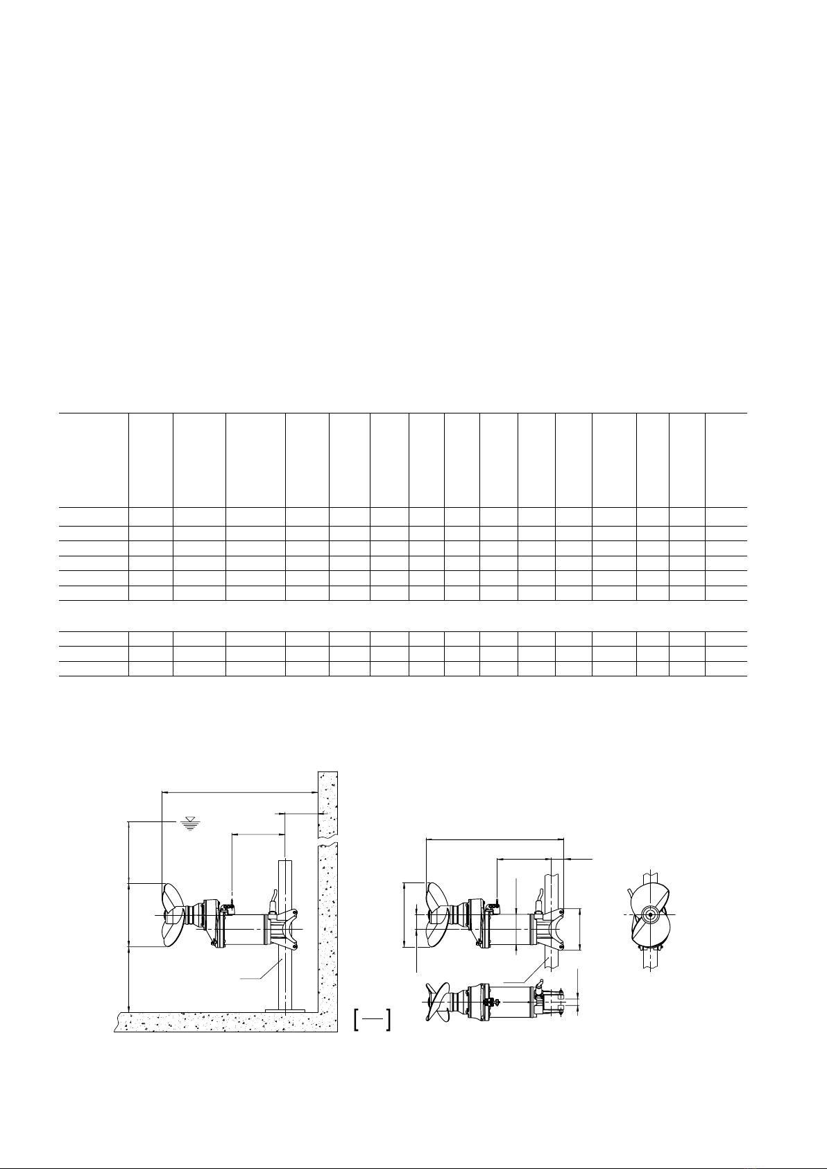
1.7 Dimensions et poids
Voir Chapitre 1.7 de l’Instructions de montage et d'utilisation 6006183 / 6005672.
1.7.1 Dimensions RW 480
1031
[40.6]
94
[3.7]
405
[15.9]
1127
[44.4]
min. 190
[min. 7.5]
405
[15.9]
□ 100
[□ 4]
ø 482
[19 dia]
min. 50
[min. 2]
ø 482
[19 dia]
109.6
[4.3]
ø 226
[8.9 dia]
312
[12.3]
47.5
[1.9]
□ 100
[□ 4]
mm
inch
min. 800
[min. 31.5 dia]
0551-0042
Figure 1 Dimensions RW 480
FR 6184-E
...
460 V
...
460 V

9
1.8 Plaque signalétique de type
Voir Chapitre 1.8 de l’Instructions de montage et d'utilisation 6006183 / 6005672.
2 - 3 Sécurité; Transport et mise en place
Voir Chapitre 2 - 3 de l’Instructions de montage et d'utilisation 6006183 / 6005672.
4 Description du produit
4.1 Description générale
Voir Chapitre 4.1 de l’Instructions de montage et d'utilisation 6006183 / 6005672.
4.2 Conception RW 480
10
962
3
81
12 11
5
7
4
0551-0043
Légende
1 Fixation
2 Entréedecâble
3 Logement de raccordement
4 Arbre de propulseur
5 Bobine de moteur
6 Support avec manille
7 Carter-moteur
8 Garniture mécanique
9 Moyeu d‘hélice / Hélice
10 Engrenage
11 Unité d‘arbre avec rotor et paliers
12 Bague SD
Figure 2 RW 480
4.3 Fonctionnement avec convertisseurs de fréquence
Voir Chapitre 4.5 de l’Instructions de montage et d'utilisation 6006183 / 6005672.
5 Installation
Voir Chapitre 5 de l’Instructions de montage et d'utilisation 6006183 / 6005672.
5.1 Installation RW 480
Voir Chapitre 5.1 de l’Instructions de montage et d'utilisation 6006183 / 6005672.
5.2 Montage de l‘hélice RW 480
Selonlaconstruction,laxationdel‘hélicesediérenciedesautresgroupesdelasérieRW/RCPouSB-KA.L‘hélicedeRW480est
xéeàl'aided'unmanchondeserrageencapsulé.
1
2
3
4
5
67
0551-0044
Légende
1 Vis à tête
2 Rondelle de l‘hélice
3 Rondelles d‘arrêt
4 Joint torique (Vis à tête)
5
Joint torique (Rondelle de l‘hélice)
6 Manchon de serrage
7 Joint torique (Moyeu)
Figure 3 Montage / Démontage de l‘hélice
Démontage
• Desserrer la vis à tête cylindrique (3/1) avec les rondelles d'arrêt (3/3), le joint torique (3/4), la rondelle de l‘hélice (3/2) et le joint torique
(3/5).
FR 6184-E

10
• Desserrer les vis du manchon de serrage (3/6) et retirer l‘hélice avec le manchon de serrage. Retirer le joint torique (3/7) de l'écrou.
ATTENTION N'utiliser aucune huile contenant du sulfure de carbone au molybdène !
• Serrer légèrement la vis du manchon de serrage en croix.
• Serrer les vis du manchon de serrage en croix selon une force de 16 Nm.Puis,vérierqueleserragealieudanslesensdesaiguilles
d'une montre.
• Placer les rondelles d'arrêt (3/3) avec le joint torique (3/4), la rondelle de l’hélice (3/2) et le joint torique (3/5) sur la vis à tête cylindrique
(3/1) et serrer selon un couple de 17 Nm.
5.3 Couple des serrage
Voir paragraphe 5.3 d‘Instructions de montage et d‘utilisation 6006183 / 6005672.
5.4 Exemple d‘installation RW 480
Pourcetyped‘installationnousrecommandonsd‘utiliserlaxationfermée
4
7
6
2
3
5
1
0551-0045
Légende
1 Potencedelevageavectreuiletcâble
2 Supportdexationsupérieur
3 Fixation fermée
4 Logement inférieur
5 Butée de serrage de sécurité
6 Tube de guidage carré orientable
7
Pinced‘extrémitéaveccrochetdecâble
Figure 4 Exemple d‘installation RW 480
5.5 Fixations RW/SB-KA
Voir Chapitre 5.5 de l’Instructions de montage et d'utilisation 6006183 / 6005672.
5.6 Longueurs des tubes de guidage (tube de guidage carré) RW/SB-KA
Voir Chapitre 5.6 de l’Instructions de montage et d'utilisation 6006183 / 6005672. RW 480 ≙RW 900.
5.7 Connections électriques
Voir Chapitre 5.8 de l’Instructions de montage et d'utilisation 6006183 / 6005672. Voir gure 32. Le Chapitre 5.8.3 ne s'applique pas au
RW 480.
6 - 7 Mise en service; Entretien
Voir Chapitre 6 - 7 de l’Instructions de montage et d'utilisation 6006183 / 6005672.
FR 6184-E

11
1 Informazioni generali
Sostanzialmente le istruzioni di montaggio e d'uso dell'Art. Nr. 6006183 / 6005672 (ABS agitatori a motore sommerso RW) valgono in
gran parte anche per l'agitatore RW 480. Lo stesso vale per il corretto collegamento e il funzionamento sicuro dell‘RW 480 in esecuzione
per atmosfere a rischio di esplosione. Lo stesso dicasi per le avvertenze di sicurezza. Queste sono contenute in un opuscolo separato
con l'Art. Nr. 1 597 0799 e debbono essere lette e studiate attentamente prima dell'installazione e della messa in funzione!
Nel presente "Supplemento" delle istruzioni montaggio e d'uso per l' ABS agitatori a motore sommerso RW 480 sono quindi con-
tenutisolorimandinonchéinformazionisupplementariespecichedelprodotto.
1.1 - 1.3 Introduzione; Utilizzo conforme; Limiti d‘impiego
Vedere capitolo 1.1 - 1.3 delle istruzioni di montaggio e d'uso 6006183 / 6005672.
1.4 Campi d‘applicazione
L'agitatoreamotoresommersoRW480servepermescolare,girareerimestareuididensicontenentisostanzesolidepresentinegli
impianti di depurazione, in uso nell'industria e nell'agricoltura. Esso è stato progettato appositamente per soddisfare le particolari richieste
di omogenizzazione di fanghi e cofermenti/substrati.
1.5 Codici identicativi
Vedere capitolo 1.5 delle istruzioni di montaggio e d'uso 1 597 0832-EU/0833-EU. *Tipo elica = Elica speciale a 2 pale per fanghi e cofermenti/substrati.
1.6 Dati tecnici
Vedere capitolo 1.6 delle istruzioni di montaggio e d'uso 6006183 / 6005672.
1.6.1 Dati tecnici RW 480, 50 Hz
Tipo miscela-
tore
Diametro elica
Numero di giri /
Riduzione
Tipo motore
Assorbimento di
potenza nominale P
1
Potenza nomi-
nale motore P2
Tippo di avviamen-
to: Diretto (D.O.L)
Tippo di avviamen-
to: stella/triangolo
Corrente nomi-
nale a 400 V
Corrente di avvi-
amento a 400 V
Tipo di cavo**
(antideagrante
e standard)
Monitoraggio
temperatura
Monitoraggio
tenuta stagna
Ex dII BT4
Guida tubolare
□ 100
Peso comples-
sivo
[mm] [1/min] [kW] [kW] [A] [A] [kg]
RW 4811 480 446/3,3 A 75/4 8,66 7,5 ●14,84 93,9 2● ● ○ ● 163
RW 4812 480 467/3,1 A 75/4 8,66 7,5 ●14,84 93,9 2● ● ○ ● 163
RW 4813 480 493/3,0 A 75/4 8,66 7,5 ●14,84 93,9 2● ● ○ ● 163
RW 4814 480 517/2,8 A 110/4 13,0 11,0 ●21,85 103,4 2● ● ○ ● 169
RW 4815 480 554/2,6 A 110/4 13,0 11,0 ●21,85 103,4 2● ● ○ ● 169
1.6.2 Dati tecnici RW 480, 60 Hz
RW 4811 480 503/3,5 A 90/4 10,2 9,0 ●15,32 103 2● ● ● 163
RW 4812 480 535/3,3 A 90/4 10,2 9,0 ●15,32 103 2● ● ● 163
RW 4813 480 561/3,1 A 130/4 15,0 13,0 ●21,88 119,9 2● ● ● 169
P1= Potenza assorbita; P2=Potenzaerogata;●=Standard;○=Optional;**Tipodicavo:ladotazionestandardprevedecavida10mconestremitàcavolibera:2=1x10Gx1.5
1.7 Dimensione e peso
Vedere capitolo 1.7 delle istruzioni di montaggio e d'uso 6006183 / 6005672.
1.7.1 Dimensioni RW 480
1031
[40.6]
94
[3.7]
405
[15.9]
1127
[44.4]
min. 190
[min. 7.5]
405
[15.9]
□ 100
[□ 4]
ø 482
[19 dia]
min. 50
[min. 2]
ø 482
[19 dia]
109.6
[4.3]
ø 226
[8.9 dia]
312
[12.3]
47.5
[1.9]
□ 100
[□ 4]
mm
inch
min. 800
[min. 31.5 dia]
0551-0042
Fig. 1 Dimensioni RW 480
IT 6184-E
...
460 V
...
460 V

12
1.8 Targhetta identicativa
Vedere capitolo 1.8 delle istruzioni di montaggio e d'uso 6006183 / 6005672.
2 - 3 Sicurezza; Trasporto e immagazzinaggio
Vedere capitolo 2 - 3 delle istruzioni di montaggio e d'uso 6006183 / 6005672.
4 Descrizione del prodotto
4.1 Descrizione in genere
Vedere capitolo 4.1 delle istruzioni di montaggio e d'uso 6006183 / 6005672.
4.2 Struttura costruttiva RW 480
10
962
3
81
12 11
5
7
4
0551-0043
Legenda
1 Supporto
2 Introduzione cavo
3 Zona di collegamento
4 Albero elica
5 Avvolgimento motore
6 Supporto con maniglia
7 Corpo motore
8 Guarnizione ad anello scorrevole
9 Mozzo dell‘elica / Elica
10 Riduzione
11 Unità albero con rotore e cuscinetti
12 Anello SD
Fig. 2 RW 480
4.3 Esercizio su convertitori di frequenza
Vedere capitolo 4.5 delle istruzioni di montaggio e d'uso 6006183 / 6005672.
5 Installazione
Vedere capitolo 5 delle istruzioni di montaggio e d'uso 6006183 / 6005672.
5.1 Installazione RW 480
Vedere capitolo 5.1 delle istruzioni di montaggio e d'uso 6006183 / 6005672.
5.2 Montaggio dell‘elica RW 480
Peresigenzecostruttiveilssaggiodell'elicasidistinguedaglialtrigruppimotoredellaserieRW/RCPeSB-KA.L'elicadelRW480è
ssatapermezzodiunaghieraincapsulata.
1
2
3
4
5
67
0551-0044
Legenda
1 Vite a testa cilindrica
2 Disco dell‘elica
3 Rondelle di sicurezza
4 O-Ring
(vite a testa cilindrica)
5 O-Ring (disco dell‘elica)
6 Ghiera
7 O-Ring (mozzo)
Fig. 3 Montaggio e smontaggio dell'elica
Smontaggio
• Smontare la vite a testa cilindrica (3/1) con rosette di sicurezza (3/3), O-ring (3/4), rondella dell'elica (3/2) e O-ring (3/5).
• Allentaredelvitidellaghiera(3/6)eslarel'elicaconlaghiera.Rimuoverel'O-ring(3/7)dallascanalatura.
IT 6184-E

13
Montaggio
• Pulire l'albero e il mozzo. Inserire un nuovo O-ring (3/7) nella scanalatura, oliare leggermente albero e ghiera (3/6).
ATTENZIONE Non usare oli contenenti molibdeno e zolfo!
• Prima stringere leggermente le viti della ghiera procedendo a croce.
• Stringere poi le viti della ghiera applicando 16 Nmsempreprocedendoacroce.Innecontrollarelacoppiadiserraggioprocedendoin
senso orario.
• Inlarelerosettedisicurezza(3/3)insemeconO-ring(3/4),rondelladell'elica(3/2)eO-ring(3/5)sullaviteatestacilindrica(3/1)e
serrare applicando 17 Nm.
5.3 Coppie di serraggio
Vedere capitolo 5.3 delle istruzioni di montaggio e d'uso 6006183 / 6005672.
5.4 Esempi di installazione RW 480
Per questo tipo di installazione si suggerisce di utilizzare il supporto chiuso.
4
7
6
2
3
5
1
0551-0045
Legenda
1
„Braccio“ da sollevamento con verricello e cavo
2 Cavalletto di supporto superiore
3 Supporto chiuso
4 Cuscinetti pavimento
5 Finecorsadissaggiodisicurezza
6 Tubazione quadra girevole
7
Dispositivo di ancoraggio con cavo e gancio
Fig. 4 Esempi di installazione RW 480
5.5 Supporti RW/SB-KA
Vedere capitolo 5.5 delle istruzioni di montaggio e d'uso 6006183 / 6005672.
5.6 Lunghezze delle guide tubolari (tubazioni quadre) RW/SB-KA
Vedere capitolo 5.6 delle istruzioni di montaggio e d'uso 6006183 / 6005672. RW 480 ≙RW 900.
5.7 Collegamento elettrico
Vedere capitolo 5.8 delle istruzioni di montaggio e d'uso 6006183 / 6005672. Vedere Fig.32. Il capitolo 5.8.3 non è rilevante l'agitatore
RW 480.
6 - 7 Messa in esercizio; Manutenzione
Vedere capitolo 6 - 7 delle istruzioni di montaggio e d'uso 6006183 / 6005672.
IT 6184-E

14
1 Generalidades
El manual de instrucciones de instalación y funcionamiento con nº de referencia 6006183 / 6005672 (ABS agitador sumergible RW) es
también válido para los componentes principales del agitador modelo RW 480. Esto vale también para la conexión adecuada y el fun-
cionamiento seguro de la variante Ex del RW 480, al igual que las Instrucciones generales de Seguridad cuyo documento con nº de
referencia 1 597 0799 debe estudiarse atentamente antes de la instalación y la puesta en marca del equipo.
Estas instrucciones “adicionales” para el agitador sumergible RW 480 corresponden a referencias cruzadas relacionada con infor-
maciónqueseaespecíca,adicionalodiferenteparaesteequipoenconcreto.
1.1 - 1.3 Introducción; Uso adecuado; Limitaciones
Ver apartado 1.1 - 1.3 de las Instrucciones de Instalación y Funcionamiento – Ref. 6006183 / 6005672.
1.4 Áreas de aplicación
ElagitadorsumergibleRW480esidóneoparalamezclayagitacióndeuídosviscososconcontenidossólidosenplantasdetratamiento
de aguas residuales, así como en la industria y en la agricultura. Está especialmente diseñado para las principales funciones de agitación
durante el proceso de homogeneización de lodos y coencimas.
1.5 Código de identicación
Ver apartado 1.5 de las Instrucciones de Instalación y Funcionamiento – Ref. 6006183 / 6005672. *Tipo de hélice = Hélice especial de 2
álabes para lodos y coencimas.
1.6 Datos técnicos
Ver apartado 1.6 de las Instrucciones de Instalación y Funcionamiento – Ref. 6006183 / 6005672.
1.6.1 Datos técnicos RW 480, 50 Hz
Modelo agita-
dor
Diámetro
hélice
Velocidad /
Desmultiplica-
ción
Tipo de motor
Potencia ab-
sorbida P1
Potencia en el
eje P2
Arranque: Di-
recto (D.O.L)
Arranque: Es-
trella/Triángul
Intensidad no-
minal a 400 V
Intensidad de
arranque a 400 V
Tipo de cable**
(Ex- y Standard)
Control de
temperatura
Detector de
humedad
Ex dII BT4
Tubo guía
□ 100
Peso total
[mm] [1/min] [kW] [kW] [A] [A] [kg]
RW 4811 480 446/3,3 A 75/4 8,66 7,5 ●14,84 93,9 2● ● ○ ● 163
RW 4812 480 467/3,1 A 75/4 8,66 7,5 ●14,84 93,9 2● ● ○ ● 163
RW 4813 480 493/3,0 A 75/4 8,66 7,5 ●14,84 93,9 2● ● ○ ● 163
RW 4814 480 517/2,8 A 110/4 13,0 11,0 ●21,85 103,4 2● ● ○ ● 169
RW 4815 480 554/2,6 A 110/4 13,0 11,0 ●21,85 103,4 2● ● ○ ● 169
1.6.2 Datos técnicos RW 480, 60 Hz
RW 4811 480 503/3,5 A 90/4 10,2 9,0 ●15,32 103 2● ● ● 163
RW 4812 480 535/3,3 A 90/4 10,2 9,0 ●15,32 103 2● ● ● 163
RW 4813 480 561/3,1 A 130/4 15,0 13,0 ●21,88 119,9 2● ● ● 169
P
1
= Potencia absorbida; P
2
=Potenciaeneleje;●=Standard;○=Opcional;**Tipodecable:10mdecableconlosextremoslibresincluidoenelsuministrostandard:2=1x10Gx1.5
1.7 Dimensiones y pesos
Ver apartado 1.7 de las Instrucciones de Instalación y Funcionamiento – Ref. 6006183 / 6005672.
1.7.1 Dimensiones RW 480
1031
[40.6]
94
[3.7]
405
[15.9]
1127
[44.4]
min. 190
[min. 7.5]
405
[15.9]
□ 100
[□ 4]
ø 482
[19 dia]
min. 50
[min. 2]
ø 482
[19 dia]
109.6
[4.3]
ø 226
[8.9 dia]
312
[12.3]
47.5
[1.9]
□ 100
[□ 4]
mm
inch
min. 800
[min. 31.5 dia]
0551-0042
Fig. 1 Dimensiones RW 480
ES 6184-E
...
460 V
...
460 V

15
1.8 Placa de características
Ver apartado 1.8 de las Instrucciones de Instalación y Funcionamiento – Ref. 6006183 / 6005672.
2 - 3 Seguridad; Transporte y almacenamiento
Ver apartado 2 - 3 de las Instrucciones de Instalación y Funcionamiento – Ref. 6006183 / 6005672.
4 Descripción del equipo
4.1 Descripción general
Ver apartado 4.1 de las Instrucciones de Instalación y Funcionamiento – Ref. 6006183 / 6005672.
4.2 Diseño de RW 480
10
962
3
81
12 11
5
7
4
0551-0043
Leyenda
1 Soporte guía
2 Entrada de cable
3 Cámara de conexiones
4 Eje de la hélice
5 Estator
6 Soporte con grillete
7 Alojamiento del motor
8 Junta mecánica
9 Protector tornillo de la hélice / hélice
10 Engranaje
11 Eje + Rotor y rodamientos
12 Anillodeector(SD)
Fig. 2 RW 480
4.3 Funcionamiento con variadores de frecuencia
Ver apartado 4.5 de las Instrucciones de Instalación y Funcionamiento – Ref. 6006183 / 6005672
5 Instalación
Ver apartado 5 de las Instrucciones de Instalación y Funcionamiento – Ref. 6006183 / 6005672.
5.1 Instalación RW 480
Ver apartado 5.1 de las Instrucciones de Instalación y Funcionamiento – Ref. 6006183 / 6005672.
5.2 Montaje de la hélice RW 480
Debidoasudiseñodeconstrucción,lacolocacióndelahélicedeestemodelodieredelrestodeequiposdelasseriesRW/RCPySB-
KA. La hélice del RW 480 está asegurada con un elemento de presión encapsulado.
1
2
3
4
5
67
0551-0044
Leyenda
1 Tornillo de cabeza hueca
2 Arandela de la hélice
3 Arandelas de bloqueo
4 Anillo tórico (Tornillo de
cabeza hueca)
5 Anillo tórico (Arandelas de
bloqueo)
6 Elemento de presión
7 Anillo tórico (Punta del eje)
Fig. 3 Montaje/desmontaje de la hélice
Desmontaje
• Retirar el tornillo de cabeza hueca (3/1) con las arandelas de bloqueo (3/3), el anillo tórico (3/4), la arandela de la hélice (3/2) y el anillo
tórico (3/5).
ES 6184-E

16
• Aojarlostornillosdelelementodepresión(3/6)yextraerlahélicejuntoconelelementodepresión.Sacarelanillotórico(3/7)dela
hendidura.
Montaje
• Limpiar con cuidado el eje y la punta. Colocar un anillo tórico nuevo (3/7) en la hendidura y engrasar ligeramente el eje y el elemento
de presión (3/6).
ATENCIÓN ¡No utilizar ningún producto que contenga bisulfuro de molibdeno!
• Apretar un poco los tornillos del elemento de presión en cruz.
• Finalmente apretar fuertemente yendo de lado a lado con un par de apriete de 16 Nm. Después, comprobar el par de apriete en cruz.
• Colocar las arandelas de bloqueo (3/3) con el anillo tórico (3/4), la arandela de la hélice (3/2) y el anillo tórico (3/5) en el tornillo de
cabeza hueca (3/1) y apretar a 17 Nm.
5.3 Pares de apriete
Ver apartado 5.3 de las Instrucciones de Instalación y Funcionamiento – Ref. 6006183 / 6005672.
5.4 Ejemplo de instalación de RW 480
Para este tipo de instalación, recomendamos la utilización del soporte guía cerrado.
4
7
6
2
3
5
1
0551-0045
Leyenda
1 Elemento de elevación con torno mural
y cable
2 Soporte superior con placa de bloqueo
3 Soporte guía cerrado
4 Placa de anclaje
5 Tope de seguridad
6 Tubo guía cuadrado giratorio
7 Abrazadera y gancho para el cable
Fig. 4 Ejemplo de instalación de RW 480
5.5 Soportes guía para RW/SB-KA
Ver apartado 5.5 de las Instrucciones de Instalación y Funcionamiento – Ref. 6006183 / 6005672.
5.6 Longitud de los tubos guía (forma cuadrada) RW/SB-KA
Ver apartado 5.6 de las Instrucciones de Instalación y Funcionamiento – Ref. 6006183 / 6005672. RW 480 ≙RW 900.
5.7 Conexión eléctrica
Ver apartado 5.8 de las Instrucciones de Instalación y Funcionamiento – Ref. 6006183 / 6005672. Ver g. 32. El apartado 5.8.3 no pro-
cede para el RW 480.
6 - 7 Puesta en servicio; Mantenimiento
Ver apartado 6 - 7 de las Instrucciones de Instalación y Funcionamiento – Ref. 6006183 / 6005672.
ES 6184-E

17
1 Allmänt
I princip gäller inmonterings- och bruksanvisning med art.-Nr. 6006183 / 6005672 (ABS dränkbar pump-omrörare RW) itill största delen också
för RW 480. Detta gäller också för den korrekta anslutningen och säker drift av Ex-utförandet av RW 480. Det samma gäller också för Säker-
hetsanvisningarna.Dessannsiettseparathäftemedart.-Nr.15970799ochskastuderasnogainnaninstallationochidriftsättning!
I denna "Tillsats"-monterings- och bruksanvisning för ABS dränkbar pump-omrörare RW 480nnsdärförbarareferenshänvisnin-
garresp.avvikande,kompletterandeochproduktspecikainformationer.
1.1 - 1.3 Inledning; Avsedd användning; Användningsbegränsningar
Se kapitel 1.1 - 1.3 i monterings- och bruksanvisning 6006183 / 6005672.
1.4 Användningsområden
Dränkmotoromröringsverk RW 480 tjänar till blandning, omröring och cirkulation av sega, fasta medier i reningsanläggningar, inom indus-
tri och lantbruk. Det är speciellt konstruerat för de speciella kraven vid homogenisering av slamm och kofermenter/kosubstrater.
1.5 Typnyckel
Se kapitel 1.5 i monterings- och bruksanvisning 6006183 / 6005672. *Propellertyp = 2-blads specialpropeller för slamm och kofermenter/
kosubstrater.
1.6 Tekniska data
Se kapitel 1.6 i monterings- och bruksanvisning 6006183 / 6005672.
1.6.1 Tekniska data RW 480, 50 Hz
Omrörartyp
Propellerdia-
meter
Varvtal / Dri-
vutväxling
Motortyp
Angiven eekt-
förbrukning P1
Angiven mo-
toreekt P2
Startsätt Direkt
(D.O.L)
Startsätt: Stjär-
na/triangel
Angiven ströms-
tyrka vid 400 V
Startströmstyr-
ka vid 400 V
Kabeltyp** (Ex-
och standard)
Temperaturö-
vervakning
Tätningsover-
vakning
Ex dII BT4
Gejdrör □ 100
Totalvikt
[mm] [1/min] [kW] [kW] [A] [A] [kg]
RW 4811 480 446/3,3 A 75/4 8,66 7,5 ●14,84 93,9 2● ● ○ ● 163
RW 4812 480 467/3,1 A 75/4 8,66 7,5 ●14,84 93,9 2● ● ○ ● 163
RW 4813 480 493/3,0 A 75/4 8,66 7,5 ●14,84 93,9 2● ● ○ ● 163
RW 4814 480 517/2,8 A 110/4 13,0 11,0 ●21,85 103,4 2● ● ○ ● 169
RW 4815 480 554/2,6 A 110/4 13,0 11,0 ●21,85 103,4 2● ● ○ ● 169
1.6.2 Tekniska data RW 480, 60 Hz
RW 4811 480 503/3,5 A 90/4 10,2 9,0 ●15,32 103 2● ● ● 163
RW 4812 480 535/3,3 A 90/4 10,2 9,0 ●15,32 103 2● ● ● 163
RW 4813 480 561/3,1 A 130/4 15,0 13,0 ●21,88 119,9 2● ● ● 169
P1=uppmätteektförbrukning;P2=eektuttag;●=standard;○=tillvall;**Kabeltyp:10mkabelmedfriaändaristandardutförande:2=1x10Gx1.5
1.7 Mått och vikter
Se kapitel 1.7 i monterings- och bruksanvisning 6006183 / 6005672.
1.7.1 Måttdata RW 480
1031
[40.6]
94
[3.7]
405
[15.9]
1127
[44.4]
min. 190
[min. 7.5]
405
[15.9]
□ 100
[□ 4]
ø 482
[19 dia]
min. 50
[min. 2]
ø 482
[19 dia]
109.6
[4.3]
ø 226
[8.9 dia]
312
[12.3]
47.5
[1.9]
□ 100
[□ 4]
mm
inch
min. 800
[min. 31.5 dia]
0551-0042
Bild 1 Måttdata RW 480
SV 6184-E
...
460 V
...
460 V

18
1.8 Typskylt
Se kapitel 1.8 i monterings- och bruksanvisning 6006183 / 6005672.
2 - 3 Säkerhet; Transport och lagring
Se kapitel 2- 3 i monterings- och bruksanvisning 6006183 / 6005672.
4 Produktbeskrivning
4.1 Generell beskrivning
Se kapitel 4.1 i monterings- och bruksanvisning 6006183 / 6005672.
4.2 Konstruktion för RW 480
10
962
3
81
12 11
5
7
4
0551-0043
Teckenförklaring
1 Fäste
2 Kabelgenomföring
3 Anslutningsutrymme
4 Propelleraxel
5 Motorlindning
6 Hållare med schackel
7 Motorghus
8 Glidringstätning
9 Propellernav / Propeller
10 Gear
11 Axelenhet med rotor och lager
12 SD - ring
Bild 2 RW 480
4.3 Drift med frekvensomformare
Se kapitel 4.5 i monterings- och bruksanvisning 6006183 / 6005672.
5 Installation
Se kapitel 5 i monterings- och bruksanvisning 6006183 / 6005672.
5.1 Installation av RW 480
Se kapitel 5.1 i monterings- och bruksanvisning 6006183 / 6005672.
5.2 Propellermontering RW 480
Beroende på konstrukrionen skiljer sig propellerinfästningen sig från andra aggregat i RW/RCP resp. SB-KA serien. Propellern i RW 480
är fastsatt med en inkapslad spännsats.
1
2
3
4
5
67
0551-0044
Teckenförklaring
1 Cylinderskruv
2 Propellerplatta
3 Låsbrickor
4 O-ring (Cylinderskruv)
5 O-ring (Propellerplatta)
6 Spännsats
7 O-Ring (Nav)
Bild 3 Propellermontage/-demontage
Demontage
• Demontera cylinderskruv (3/1) med Låsbrickor (3/3), O-Ring (3/4), propellerplatta (3/2) och O-Ring (3/5).
• Lossa skruvarna i spännsats (3/6) och dra av propellern tillsammans med spännsatsen. Ta bort O-Ring (3/7) från spåret.
SV 6184-E

19
Montage
• Rengör axel och nav. Sätt in ny O-ring (3/7) i spåret och olja in axel och spännsats (3/6) lätt.
OBSERVERA Använd inga oljor som innehåller molybden-svavelkolämnen!
• Dra först fast skruvarna lätt i spännsatsen, korsvis.
• Dra fast skruvarna i spännsatsen korsvis med 16 Nm. Kontrollera sen åtdragningsmomenten runt om medurs.
• Stick på låsbrickorna (3/3) tillsammans med O-Ring (3/4), propellerplatta (3/2) och O-Ring (3/5) på cylinderskruv (3/1) och dra åt med
17 Nm.
5.3 Åtdragningsmoment
Se kapitel 5.3 i monterings- och bruksanvisning 6006183 / 6005672.
5.4 Installationsexempel RW 480
För denna installationstyp rekommenderar vi att det slutna fästet används.
4
7
6
2
3
5
1
0551-0045
Teckenförklaring
1 Lyft med talja och rep
2 Övre bock
3 Slutet fäste
4 Golvstöd
5 Säkerhetsklämma
6 Vridbart fyrkantsrör
7 Spännklämma med kabelhakar
Bild 4 Installationsexempel RW 480
5.5 Fästen RW/SB-KA
Se kapitel 5.5 i monterings- och bruksanvisning 6006183 / 6005672.
5.6 Gejdrör (fyrkantsledrör) RW/SB-KA
Se kapitel 5.6 i monterings- och bruksanvisning 6006183 / 6005672. RW 480 ≙ RW 900.
5.7 Elektrisk anslutning
Se kapitel 5.8 i monterings- och bruksanvisning 6006183 / 6005672. Se Bild 32. Kapitel 5.8.3 är inte relevant för RW 480.
6 - 7 Idrifttagande; Underhåll
Se kapitel 6 - 7 i monterings- och bruksanvisning 6006183 / 6005672.
SV 6184-E

20
1 Generelt
Principielt er en stor del af monterings- og betjeningsvejledning med art.-nr. 6006183 / 6005672 (ABS omrørere med undervandsmotor RW)
også relevant for RW 480.
Det gælder også for den passende tilslutning og sikre drift af Ex-udgaven fra RW 480. Det samme gælder for
sikkerhe-
dsanvisningerne.
Dendesietseparathæftemedart.-nr.15970799ogskallæsesomhyggeligtigennemindeninstallationogibrugtagning!
I denne "ekstra" monterings- og betjeningsvejledning for (ABS omrørere med undervandsmotor RW) 480ndesderforkunkryd-
shenvisningerelleryderligereinformationer,dererentenafvigendeellerspecikkeforproduktet.
1.1 - 1.3 Introduktion; Bestemmelsesmæssig anvendelse; Anvendelsesområder
Se kapitel 1.1 - 1.3 i monterings- og betjeningsvejledning 6006183 / 6005672.
1.4 Anvendelsesområder
OmrøreremedundervandsmotorRW480brugestilblanding,omrøringogcirkuleringafsejt,fastydendemediumirenseanlægtilbåde
industri og landbrug. Det er beregnet specielt til de krav, der stilles til homogenisering af slam og coenzymer.
1.5 Typekoder
Se kapitel 1.5 i monterings- og betjeningsvejledning 1 597 0832-EU/0833-EU. *Propeltype = 2-blad specialpropel beregnet til slam og coenzymer.
1.6 Tekniske data
Se kapitel 1.6 i monterings- og betjeningsvejledning 6006183 / 6005672.
1.6.1 Tekniske data RW 480, 50 Hz
Omrørertype
Propeldiameter
Omdrejnings-
tal / Gearre-
duktion
Motortype
Nominel ind-
gangseekt P1
Motorens nomi-
nelle eekt
P2
Startmåde:
direkte (D.O.L)
Startmåde:
stjerne/trekant
Nominel strøm
ved 400 V
Startstøm ved
400 V
Kabeltype**
(Ex- og Standard)
Temperaturo-
vervågning
Tætningsover-
vågning
Ex dII BT4
Guiderør □ 100
Totalvægt
[mm] [1/min] [kW] [kW] [A] [A] [kg]
RW 4811 480 446/3,3 A 75/4 8,66 7,5 ●14,84 93,9 2● ● ○ ● 163
RW 4812 480 467/3,1 A 75/4 8,66 7,5 ●14,84 93,9 2● ● ○ ● 163
RW 4813 480 493/3,0 A 75/4 8,66 7,5 ●14,84 93,9 2● ● ○ ● 163
RW 4814 480 517/2,8 A 110/4 13,0 11,0 ●21,85 103,4 2● ● ○ ● 169
RW 4815 480 554/2,6 A 110/4 13,0 11,0 ●21,85 103,4 2● ● ○ ● 169
1.6.2 Tekniske data RW 480, 60 Hz
RW 4811 480 503/3,5 A 90/4 10,2 9,0 ●15,32 103 2● ● ● 163
RW 4812 480 535/3,3 A 90/4 10,2 9,0 ●15,32 103 2● ● ● 163
RW 4813 480 561/3,1 A 130/4 15,0 13,0 ●21,88 119,9 2● ● ● 169
P1=Indgangseekt;P2=Udgangseekt;●=Standard;○=Ekstratilbehør;**Kabeltype:10mkablermedfrikabelendeerdelafstandardieveringsomfanget:2=1x10Gx1.5
1.7 Dimensioner og vægte
Se kapitel 1.7 i monterings- og betjeningsvejledning 6006183 / 6005672.
1.7.1 Konstruktionsmål RW 480
1031
[40.6]
94
[3.7]
405
[15.9]
1127
[44.4]
min. 190
[min. 7.5]
405
[15.9]
□ 100
[□ 4]
ø 482
[19 dia]
min. 50
[min. 2]
ø 482
[19 dia]
109.6
[4.3]
ø 226
[8.9 dia]
312
[12.3]
47.5
[1.9]
□ 100
[□ 4]
mm
inch
min. 800
[min. 31.5 dia]
0551-0042
Figur 1 Konstruktionsmål RW 480
DA 6184-E
...
460 V
...
460 V
Table of contents
Languages:
Other Sulzer Mixer manuals
Popular Mixer manuals by other brands

Panasonic
Panasonic MX-AC400WRA Service manual

Celme
Celme MO-350 VV Installation - use - maintenance

Slate Media Technology
Slate Media Technology RAVEN Core Station Assembly manual

Rane
Rane AM1 Operator's manual

Dash
Dash delish DCSM350 instruction manual

Feider Machines
Feider Machines FM1600-A instruction manual