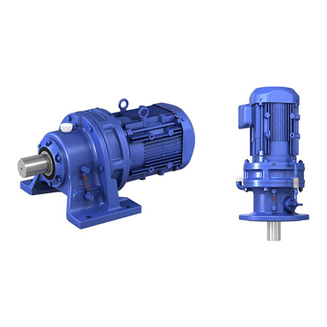
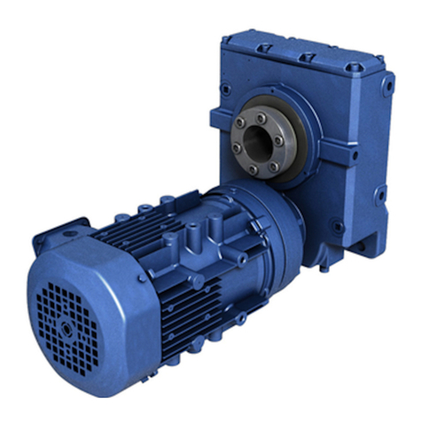
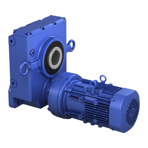
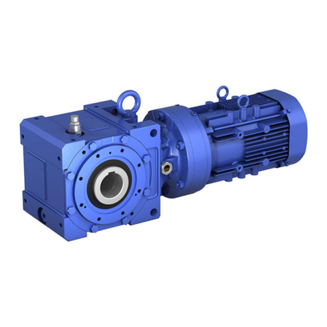
Sumitomo ALTAX NEO User manual

Maintenance manual No.CM2015E-8
■The product should be handled by an experienced and skilled personnel.
Read the maintenance manual thoroughly before using the product.
■The maintenance manual should be delivered to a customer who uses the product.
■Make sure the maintenance manual should be stored securely.
ALTAX® NEO
Gearmotor
Reducer
Application Product : ALTAX®NEO with Current Limiter
<<CAUTION>>


1
Introduction: Safety Precautions
- Carefully read this maintenance manual and all accompanying documents before use (installation,
operation, maintenance, inspection, etc.). Thoroughly understand the machine, information about
safety, and all precautions for correct operation.
After reading, retain this manual for future reference.
- Pay close attention to the "DANGER" and "CAUTION" warnings regarding safety and proper use.
DANGER Improper handling may result in physical damage, serious personal injury
and/or death.
CAUTION Improper handling may result in physical damage and/or personal injury.
Matters described in CAUTION may lead to serious danger depending on the situation.
Be sure to observe important matters described herein.
DANGER
- Transport, installation, plumbing, wiring, operation, maintenance, and inspections should be
performed by trained technicians; otherwise, electric shock, injury, re, or damage to the equip-
ment may result.
- In the case of maintenance with disassembly, please contact the nearest authorized service
station.
- When using the equipment in conjunction with Explosion proof motor , a technician with
electrical expertise should supervise the transport, installation, plumbing, wiring, operation,
maintenance and inspection of the equipment; otherwise, explosion, ignition, electric shock,
personal injury, re or damage to the equipment may result.
- When the unit is to be used in a system for human transport a protecting device for human
safety should be installed to prevent chances of accidents resulting in personal injury, death, or
damage to the equipment due to running out of control or falling.
- When the unit is to be used for an elevator or lifter, install a safety protecting device on the
elevator side to prevent it from falling; otherwise, personal injury, death, or damage to the
equipment may result.
CAUTION
Please install loss prevention device such as oil pan to the machine which is vulnerable to oil
especially (machine for food processing and machine for clean room, and so on) in case oil or
grease leaks; otherwise, the product may fail because of oil leakage.

22
Introduction: How to Refer to the Maintenance Manual, Table of Contents
This maintenance manual is common for “gearmotors”, “reducers”.
The symbols shown below appear in the upper right or left corner of each page to indicate the
classication. Please read the applicable pages.
On Common pages, symbols identify distinctions between specic specications.
Specications
All Specications
Are Common
Gearmotor Reducer Application
Product
Without brake With brake
Symbol
Contents
Common
Introduction: Safety Precautions ………………………………………………………………… 1
Introduction: Reading the Maintenance Manual, Table of Contents ………………………… 2
1. Inspection Upon Delivery ……………………………………………………………………… 3
2. Storage …………………………………………………………………………………………… 7
3. Transport ………………………………………………………………………………………… 8
4. Installation ……………………………………………………………………………………… 9
5. Coupling with Other Machines ………………………………………………………………… 11
6. Wiring …………………………………………………………………………………………… 13
7. Operation ………………………………………………………………………………………… 33
8. Daily Inspection and Maintenance …………………………………………………………… 36
9. Troubleshooting ………………………………………………………………………………… 55
10. Construction Drawings ………………………………………………………………………… 57
Application Product : ALTAX®NEO with Current Limiter
11. Specication, Installation …………………………………………………………………… 62
12. Wiring …………………………………………………………………………………………… 63
13. Setting ………………………………………………………………………………………… 64
14. Operation ……………………………………………………………………………………… 65
Common
15. Warranty ………………………………………………………………………………………… 66
Common Application
Product

32
1. Inspection upon Delivery Common
32
CAUTION
- Unpack the unit after verifying that it is positioned right side up; otherwise, injury may result.
- Verify that the unit received is in fact the one you ordered. Installing the wrong unit may result
in personal injury or equipment damage.
- Do not remove the nameplate
Verify the items listed below upon receiving the product. If a nonconformity or problem is found, please
contact with your nearest agent, distributor, or sales oce.
[1] Does the information on the nameplate conform to what you ordered?
[2] Was any part broken during transport?
[3] Are all bolts and nuts tightened rmly?
1-1 Reading the Nameplates
There are two main types of nameplates: type 1 and type 2. Representative examples are shown below.
Please observe them by type.
When contacting the company, please provide [1] Gearmotor or reducer type/specication symbol,
[2] Reduction ratio, and [3] Production number (Serial number).
[1] Gearmotor type (see P4)/
specication symbol (see P5)*
[2] Reduction Ratio
- Motor capacity
- Motor characteristics
- Brake for motor with brake
Current value
[3] Serial number
- Motor type (see P6)
- Brake for motor with brake
(see P6)
- Motor frame size
Figure 1-1 Gearmotor nameplate (type 1)
- Brake torque
for motor with brake
- Nameplate Type 2: Separate Nameplates for Gear Unit and Motor Unit.
- Nameplate Type 1: Gear Unit and Motor Unit Are Combined.
[1] Gearmotor, Reducer Type (see P4)/
specication symbol
(see P5)*
[2] Reduction Ratio
- Input capacity, speed
- Allowable output torque
[3] Serial number
- Motor type (see P6)
- Brake type
for motor with brake
(see P6)
- Motor frame size
- Brake torque
for motor with brake
[3] Serial number
- Brake current value for motor with brake
- Motor capacity - Motor characteristics
Figure 1-2 Gearmotor, Reducer nameplate (type 2)
(Gear unit nameplate) (Motor unit nameplate)
* The specication symbol may not be on the nameplate.
Note: The reducer has a nameplate only on the gear unit.
MODEL
B.AMP
M.AMP
r/min
SERIALNo.
Hz
VOLTS
RATIOOUTPUTRATING
TYPE
RATING
FRAME
N・m
N・mB.TORQUE
JISC4034-1
M/BTHERMA
PØ
2D
Code
OUTPUTRATING N・m SERIALNo.
INPUT r/min
RATIO
MODEL
2D
Code
ØP TYPE
M.AMP
Hz
VOLTS
P.F.
r/min
FRAME
M.THERM
RATING
N・mB.TORQUE
EFF. B.THERMAL
JISC4213
DTT961W
B.AMP S/N
kW
2D
Code

44
Common 1. Inspection upon Delivery
C N H M 01
5087
B
87
Model Symbol
C ALTAX NEO
P
ALTAX
Low Reduction Ratio
Series With or Without Brake
Blank Without Brake
B With brake
C
With One-Touch Release
type Brake
Reduction ratio
Mounting style
H Foot
V Flange
Motor connection method
M Gearmotor
Blank Reducer
(free shaft)
Motor capacity
symbol (4P)
004 40W
006 60W
009 90W
01 0.1kW
02 0.2kW
03 0.25kW
05 0.4kW
08 0.55kW
1 0.75kW
1H 1.1kW
2 1.5kW
3 2.2kW
5 3.7kW
Slow Speed Shaft Direction
N Universal mounting
Sux Motor type
Blank* With 3-phase motor
EP With Premium-Eciency, 3-Phase Mo-
tor
AV With 3-phase motor for inverter
AP With Premium-eciency,
3-phase motor for inverter
ES With High-eciency 3-phase motor
CA With single phase motor (capacitor
run)
CB With single phase motor
(capacitor starting, capacitor run)
CC With single phase reversible motor
* Only for gearmotor
1-2 Lubrication Method
ALTAX NEO and ALTAX Low Reduction Ratio Series adopt grease lubrication and grease is applied when
shipped from the factory, therefore lubrication is not needed and use out of the box.
1-3 Gearmotor, Reducer Type
Symbol meanings are shown below. Please conrm that the type matches the order.
Frame Size
ALTAX NEO
CYCLO mechanism, single
reduction type
5067
506H 5077 5087 5097 5107 5117 5127
Traction drive - 507R 508R 509R 510R -
CYCLO mechanism, single
reduction type + Traction drive - 5097DR 5107DR 5117DR 5127DR
5127DS
CYCLO mechanism, double
reduction type - 5097DA 5107DA 5117DA 5127DA
ALTAX
Low Reduction Ratio
Series
Planetary gear mechanism
5081
5082
5083
5093 5103 5113

54
1. Inspection upon Delivery
4
1-4 Gearmotor Specication Symbol
Symbol meanings are shown below. Please conrm that the type matches the order.
A specication symbol is described on the nameplate when a customer specied at its order.
JP AL
2N
xxth Digit
3rd Digit
Operating environment
N
A
B
W
9
Indoor
Outdoor
Light dust proof type
Waterproof (IP65)
Others
5th Digit
Terminal box mounting position
(View from output side)
Left
Top
Right
Bottom
L
T
R
B
▼ ▼
▼
Without
terminal box
[1] [2] [3] [4] [5] [6]
4th Digit
Type of terminal box
Q
P
T
S
B
A
C
X
Resin, terminal block type
Resin, lug type
Steel, terminal block type
Steel, lug type
Aluminum, terminal block type
Aluminum, lug type
With cabtyre cable
Without terminal box
▼
▼▼
1st Digit
Country code
* Applies to a motor for inverter.
(Type with base frequency of 60Hz is as standard.)
Voltage
Voltage (V)Frequency (Hz)
J
Japan
2200/200/220 50/60/60
200/220 60/60
4400/400/440 50/60/60
400/440 60/60
1 100/100 50/60
D 100/100/200/200 50/60/50/60
U
U.S.A
B 230/460 60
5 230 60
6 460 60
A
Canada
B 230/460 60
E
Europe
2 200 50
C 220/380 50
60
8 230/400 50
60
4 400 50
60
C
China
A 220 50
C 220/380 50
60
3380 50
380/400/41550
K
Korea
C 220/380 60
4 440 60
F
South East
Asia
(Excluding Singapore)
8 230/400 50
60
4 400 50
60
*
*
*
*
*
*
*
*
2nd Digit
A
AType
B
BType
C
CType
D
DType
X
6th Digit Lead wire direction

66
1. Inspection upon Delivery
1-5 Motor Type
Symbol meanings are shown below. Please conrm that the specication matches the order.
1-6 Brake Type
Table 1-1 shows the relationship between standard brake type and motor type and capacity range.
Table 1-1 Brakes
Brake type
Motor Capacity (kW)
3-phase motor
Premium-
Eciency
3-phase motor
3-phase motor
for inverter
Premium-
eciency,
3-phase motor
for inverter
High-eciency
3-phase motor
Single phase
motor
MB-003 40W - - - - 40W
MB-005 60W - - - - 60W
MB-010
90W
- - - - 90W
0.1
(frame size
5067 only)
FB-01A1 0.1 - - - - 0.1
FB-02A1 0.2 0.25 - 0.1 - - 0.2
FB-05A1 0.4 - 0.2 - 0.2 -
FB-1D 0.55 - 0.4 - 0.4 0.4
FB-1E - 0.75 - 0.75 - -
FB-1HE - 1.1 - - - -
FB-2E - 1.5 - 1.5 - -
FB-3E - 2.2 - 2.2 - -
FB-5E - 3.7 - 3.7 - -
Note: 1. Brake type may dier from the types shown in Table 1-1 depending on specication.
Check the nameplate.
2. 3-phase motor 0.1kW frame size5067 is MB-010.
Type
S
Blank
Single phase
3-phase
Type of Sheath
TTotally enclosed
Drive Power Source
V
Blank
Inverter drive
(motor for inverter)
Commercial power driven
Protection Type
A
Increased safety explosion proof, indoor type
Increased safety explosion proof, outdoor type
Outdoor type (non-explosion proof)
Indoor type (non-explosion proof)
B
X
Blank
Cooling Type
EFanless (self-cooling)
With self-ventilating fan (external fan)
F
S
▼
E
▼
Other Specication
A
UL, NEMA, CSA Specication (230, 240, 460, 480V)
C
UL, NEMA, CSA Specication (575V)
Motor Other Than Above
Blank
X
▼
▼
▼
T
Rotor Symbol
C
K
Normal box
Special box
C
▼
Support for Standards and Regulations
E
P
High-eciency motor
(IEC standard)
Premium eciency motor
Blank
Motor other than above
▼
▼

76
2. Storage Common
6
If this product is not for immediate use, note the following points when storing it.
2-1 Storage Location
Store the product indoors in a clean, dry location.
Do not store outdoors. Store in a location that is free of moisture, dust, extreme temperature changes,
corrosive gases, etc.
2-2 Storage Time
- The storage time should be within one year.
- If the storage time exceeds one year, adherence to special rust prevention specications is required.
Please consult with us.
- If for export, adherence to export rust prevention specications is required. Please consult with us.
- Standard rust prevention specications
External rust prevention Rust prevention oil is applied when shipping from the factory. Check rust
conditions every six months after shipment. Reapply the rust prevention
process, if necessary.
Internal rust prevention Store in an ordinary factory or warehouse in an environment free of
moisture, dust, extreme temperature changes, corrosive gases, etc.
2-3 Using after Storage
- Oil seals are aected by temperature, ultraviolet light and other ambient conditions and can easily
degrade. After long storage periods, inspect before operation, and replace any degraded seals with new
seals.
- At startup, check that there are no unusual noises, vibrations, temperature rises, or other symptoms. For
motor with brakes, check that brakes work properly. If any abnormalities are found, immediately contact
the nearest authorized service station.

88
Common 3. Transportation
DANGER
- Do not stand directly under a unit suspended by a crane or other lifting mechanism;
otherwise, injury, or death may result.
CAUTION
- Exercise ample care so as not to drop the unit.
When a hanging bolt or hole is provided, be sure to use it. After mounting a unit to a machine,
do not hoist the entire machine using the hanging bolt or hole; otherwise, personal injury or
damage to the equipment and/ or lifting device may result.
- Before hoisting, refer to the rating plate, crate, outline drawing, catalog, etc. for the weight
of the unit. Never hoist a unit that exceeds the rating of the crane or other mechanism being
used to lift it; otherwise, personal injury or damage to the equipment and/or lifting device
may result.
- Use an appropriate hanging bolt or hole, and make sure that the eye-bolt and/or nut is not
loose before hoisting.

98
4. Installation Common
8
DANGER
- Do not use a standard unit in an explosive atmosphere (which is likely to be lled with
explosive gas or steam). Under such conditions, an explosion-proof motor should be used;
otherwise, electric shock, personal injury, explosion re, or damage to the equipment may
result.
- In the case of an Explosion proof motor , use a motor that has specications that are appropriate
for a dangerous location (a location where gas or volatile vapor is present); otherwise explosion,
ignition, electric shock, injury, re, or equipment damage may result.
CAUTION
- Do not use the products for purposes other than those shown on the nameplate or in the
manufacturing specications; otherwise, electric shock, personal injury, or damage to the
equipment may result.
- Do not place ammable objects around the gearmotor; otherwise, re may result.
- Do not place any object around the gearmotor or reducer that will hinder ventilation.
Insucient ventilation can cause excessive heat build-up that may result in burns or re.
- Do not step on or hang from the gearmotor or reducer; otherwise injury may result.
- Do not touch the shaft end of the gearmotor or reducer, inside keyways, or the edge of the
motor cooling fan with bare hands; otherwise, injury may result.
- When the unit is used in food processing applications, machines for cleanroom and so on,
vulnerable to oil contamination, install an oil pan or other such device to cope with oil leakage
due to breakdown or failure; otherwise, oil leakage may damage products.
4-1 Installation Location
Ambient temperature: −10 to +40℃
Ambient humidity: 85%RH or less with no condensation
Altitude: Maximum 1,000 m
Atmosphere: No corrosive or volatile gases, no steam
Dust-free, well-ventilated area.
Installation location: Indoor type: Indoors (area with minimal dust, no contact with water)
Outdoor type: Indoors or outdoors (place where are got wet with common
rainwater not but direct heavy wind and rain)
Waterproof type: Protection class IP65
The product is resistant to water jet from a jet nozzle from any
directions.
The product is not allowed to use under water or high water
pressure.
Vibration: Maximum 1G
- Mounting in conditions other than the above requires adherence to optional specications. Please
consult with us.
- Drives built to specications, such as explosion proong, can be used in the specied mounting
environments. However, concerning the connector to the machine used, implement measures based
on the mounting environment.
- Mount in a location that enables easy operation, such as inspection and maintenance.
- Mount on a suciently rigid base.

1010
Common 4. Installation
4-2 Mounting Angle
There is no limit on a mounting angle.
There is no limitation on a mounting angle unless it is originally specied the certain angle in manufac-
turing.
Do not remove the motor’s eye-bolt. In the rare case that it is removed, insert a bolt or other
appropriate material into the screw hole to prevent water or other substances from entering the
motor through the screw hole.

1110
5. Coupling with Other Machines Common
10
CAUTION
- Conrm the rotation direction before coupling the unit with the driven machine. Incorrect
rotation direction may cause personal injury or damage to the equipment.
- When operating the product alone (uncoupled), remove the key that is temporarily attached
to the slow speed shaft; otherwise the key could y o, and injury may result.
- Cover rotating parts; otherwise, injury may result.
- When coupling the product with a load, check that the centering, the belt tension and
parallelism of the pulleys are within the specied limits. When the unit is directly coupled with
another machine, check that the direct coupling accuracy is within the specied limits. When
a belt is used for coupling the unit with another machine, check the belt tension. Correctly
tighten bolts on the pulley and coupling before operation; otherwise, injury may result
because of misalignment.
5-1 Checking Rotational Direction
(1) For gearmotor
Table 5-1 shows the direction of slow speed shaft rotation when wiring is performed as on P16 – 30.
Table 5-1 Slow Speed Shaft Rotation Direction (Gearmotor)
When wiring is performed as shown on P16 – 30, the motor shaft rotates to the right as seen from the anti-load side.
In the following diagrams, arrows show the direction of slow speed shaft rotation in this case.
Frame Size
ALTAX NEO
ALTAX
Low Reduction Ratio
Series
5067, 506H, 5077, 5087
5097, 5107, 5117, 5127
5097DR, 5107DR, 5117DR
5127DR, 5127DS
507R, 508R
509R, 510R
5097DA, 5107DA
5117DA, 5127DA
5081, 5082
5083, 5093
5103, 5113
Slow speed shaft
Rotation direction
(Seen from load side)
Note: 1. Switch the SW in the connection diagram on P18 and P26 to rotate a 40 to 90W single phase power
source motor in reverse direction.
2. Reverse Z1 and Z2 in the connection diagram on P19 and P27-30 to rotate a 0.1 to 0.4kW single
phase power source motor in reverse direction.
3. Reverse R and T in the connection diagram on P16 and P20-23 to rotate a 3-phase power source
motor in reverse direction.
(2) For reducer
Table 5-2 Slow Speed Shaft Rotation Direction (Reducer)
Frame Size
ALTAX NEO
ALTAX
Low Reduction Ratio
Series
5067, 5077, 5087
5097, 5107, 5117, 5127
5097DR, 5107DR
5117DR, 5127DR
507R, 508R
509R, 510R
5097DA, 5107DA
5117DA, 5127DA
5081, 5082
5083, 5093
5103, 5113
Slow speed shaft
Rotation direction
Rotates in reverse direction as the
high speed shaft.
Rotates in same direction as the
high speed shaft.

1212
Common 5. Coupling with Other Machines
5-2 Mounting Connected Equipment
- When mounting connected equipment, do not apply impact or
excessive axial load to the shaft. The bearing could be damaged,
or the collar could come o.
- Shrinkage or shaft-end screw t is recommended (see Figure 5-1).
(1) When using a coupling
The alignment accuracy (A, B, X) in gure 5-2 should be no greater than that shown in Table 5-3.
(2) When using chains, sprockets, or gears
- When using a chain, attach so that the chain tension angle is perpendicular to the shaft.
- Refer to the chain catalog or other reference for chain tension.
- Select a sprocket or gear pitch diameter that is at least three times the shaft diameter.
- The working load point of the sprocket or gear should go from the center of the shaft to this product.
(See Figure 5-3)
(3) When using a V belt
- Over-tightening the V belt will damage the shaft and bearing. Refer to the V belt catalog or other
reference for V belt tension.
- The parallelism, eccentricity β of the two pulleys should be within 20´. (See Figure 5-4)
- When using multiple V belts, use a matched set having the same length.
Table 5-3 Alignment Precision for Flexible
Coupling
Allowable
tolerance A
0.1 mm or
manufacturer-
specied value
Allowable
tolerance B
0.1 mm or
manufacturer-
specied value
Xmanufacturer-
specied value
X
A
X
B
Figure 5-1
Figure 5-2
Figure 5-3 Figure 5-4
Connected equipment
This product
Shaft
β
β
Connected
equipment
Shaft
Shaft-end screw

1312
6. Wiring
12
When using other manufacturer’s motor, follow the operation manual for that motor.
This manual shows wiring for motors with Japanese standard specications. Please consult with us for
motors with overseas specications.
DANGER
- Do not handle the unit when cables are live. Be sure to turn o the power; otherwise, electric
shock may result.
- Connect a power cable to the unit according to the diagram shown inside the terminal box or
in the maintenance manual; otherwise, electric shock or re may result.
- Do not forcibly bend, pull, or clamp the power cable and lead wires; otherwise, electric shock
or re may result.
- Correctly ground the grounding bolt; otherwise, electric shock may result.
- The lead-in condition of an explosion proof motor shall conform to the facility’s electrical
codes, extension regulations and explosion-proong guide, as well as the maintenance
manual; otherwise, electric shock, personal injury, explosion, re or damage to the equipment
may result.
- For an explosion proof motor and single phase power source motor , inverter drive is not
allowed.
CAUTION
- When wiring, follow the facility’s electrical codes and extension regulations; otherwise,
burning, electric shock, injury, or re may result.
- The motor is not equipped with a protection device. However, it is compulsory to install an
overload protector according to facility electrical codes. It is recommended to install other
protective devices (earth leakage breaker, etc.), in addition to an overload protector, in order
to prevent burning, electric shock, injury, and re.
- Never touch the terminals when measuring insulation resistance; otherwise, electric shock
may result.
- Voltage PWM inverters that use IGBT generate high-voltage surges at the motor terminals,
which may degrade the insulation on the motor windings. Especially such as when the cable
is long in the 400V class, a surge voltage over 1300V occurs. Therefore, in this case, install an
LCR lter, AC reactor, etc. between the inverter and motor to inhibit the surge voltage.
- When using a motor with brake, do not turn on connection power to the brake coil when the
motor is stopped. Otherwise coil burnout re, may result. Also, mistaken wiring could damage
the rectier.
- When measuring the insulation resistance of an explosion proof motor, conrm that there is
no gas or explosive vapor in the vicinity, in order to prevent possible explosion or ignition.
- If ambient temperature exceeds 60℃, place the rectier in a location where the temperature
is 60℃or less. In this case, always protect the entire rectier with a cover. However,
standard ambient temperature conditions for units with and without brakes is −10 to 40℃.
(Manufacture to special specication is required for operation in an environment where
ambient temperature exceeds 40℃.)
- Long cables cause large voltage drops. Select cables with appropriate diameter so that the
voltage drop will no greater than 2%.
- After wiring outdoor types and explosion proof types, check that terminal box mounting
bolts are not loose, and correctly attach the terminal box cover.
-
For a single phase motor, do not take a starting capacitor as an operation capacitor when us-
ing it. Otherwise, the capacitor will be damaged.
-
For a single phase motor, do not scratch a plastic lm of the starting capacitor. Otherwise,
electric shock may result.

14
6. Wiring
6-1 Removing and Attaching the Resin Terminal Box Cover
3-phase motor: 0.1–0.4kW, high-eciency, 3-phase motor: 0.2kW, 3-phase motor for inverter: 0.1–0.2kW
(1) Removal
As shown in gure 6-1, to remove the cover, grab the sides of the
terminal box, and pull it toward you.
(2) Attachment
Push the terminal box cover from above the terminal box case
until a click is heard.
6-2 Measuring Insulation Resistance
When measuring insulation resistance, always disconnect the control panel and measure the motor alone.
Measure insulation resistance before wiring. Insulation resistance (R) is changed by a number of factors,
including motor output, voltage, type of insulation, winding temperature, moisture, degree of fouling,
time used, and amount of time test voltage is applied. However, normally, it must be above the values in
Table 6-1.
Table 6-1 Values for Insulation Resistance
Motor voltage Megohmmeter Voltage Insulation Resistance (R)
Low-voltage electric motors of no more than 600V 500V Minimum 1 MΩ
Low insulation resistance is a sign that there is an insulation failure. Do not apply power. Consult an ac-
credited service station.
6-3 Coordination of System Protection
- Use a wiring breaker for short circuit proong.
- Use an overload protection device designed to handle currents that exceed the rated current on the
nameplate.
- For increased safety, explosion proof motors, use an overload protection device capable of protecting
the locked rotor current on the nameplate within the allowable locking time.
6-4 Connecting the Power Cable.
Connect the power cable and motor lead wire by clasping in a
pressure connection terminal as shown in Figure 6-2.
Reference: JEC -2100 contains the following equation:
Rated Voltage (V) + (RPM/3)
R ≧+ 0.5 (MΩ)
Rated output power (kW) + 2,000
Rated Voltage (V)
R ≧(MΩ)
Rated output power (kW) + 1,000
Figure 6-2
Power source cable
Motor lead wire
Insulating tape
Fig. 11
Figure 6-1

1514
6. Wiring
6-5 Motor Wiring
Shows the pages for motor wiring diagrams.
Table 6-2 Without Brake
Motor type Capacity range
(kW)
Number of
lead wires
Page
Direct input from
commercial
power source
Inverter
drive
3-phase motor
Standard 40W–0.55 3 P16 P17
Increased safety,
explosion proof 0.1 - 3.7 3 P16 -
Premium-
Eciency,
3-Phase Motor
Standard 0.75 - 3.7 3 P16 P17
Increased safety,
explosion proof 0.75 - 3.7 3 P16 -
Premium-eciency,
3-phase motor 0.1 - 0.4 3 - P17
Premium-eciency,
3-phase motor
for inverter
0.75 - 3.7 3 - P17
High-eciency 3-phase motor 0.2 - 0.4 3 P16 P17
Single phase motor 40W–90W 3 P18
-0.1 - 0.4 6 P19
Single phase reversible motor 40W - 90W 3 P18
Table 6-3 With Brake
Motor type Capacity range
(kW)
Brake
type
Number of
lead wires
Page
One-direction
rotation
Both-direction
Rotation Inverter Drive
3-phase motor
40W MB-003
5
P20 P22 P24
60W MB-005
90W
MB-010
0.1*
Frame size 5067 only
0.1 FB-01A1
P21 P23 P25
0.2 0.25 FB-02A1
0.4 FB-05A1
0.55 FB-1D
Premium-Eciency
3-phase motor
0.75 FB-1E
5 P21 P23 P25
1.1 FB-1HE
1.5 FB-2E
2.2 FB-3E
3.7 FB-5E
Premium-eciency,
3-phase motor
0.1 FB-02A1
5 - - P250.2 FB-05A1
0.4 FB-1D
Premium-eciency,
3-phase motor
for inverter
0.75 FB-1E
5 - - P25
1.5 FB-2E
2.2 FB-3E
3.7 FB-5E
High-eciency 3-phase motor 0.2 FB-05A1 5 P21 P23 P25
0.4 FB-1D
Single phase motor
40W MB-003
5 P26 P26 -60W MB-005
90W MB-010
0.1 FB-01A1
8P27 P29 -0.2 FB-02A1
0.4 FB-1D P28 P30
* For motors with standard Japanese domestic specications. Please consult with us for motors with over-
seas specications.
Note: 1. Brake type may dier depending on specication. Check the nameplate.
2. 3-phase motor 0.1kW frame size5067 is MB-010.

16
6. Wiring
Shows motor wiring and standard specication for terminals and lead wires that are indicated by symbols.
■Without brake. 3-phase power source
3-phase motor
Premium-Eciency, 3-Phase Motor
High-eciency 3-phase motor
3 Lead Wires
40–90W, 0.1kW (frame size 5067 only) 0.1–3.7kW
Control Panel
Control Panel
Motor
Motor
MC : Electromagnetic contactor
OLR : Overload protection device or electronic thermal relay
- This diagram shows cases for motors with standard Japanese domestic specications. Please consult
with us for motors with overseas specications.
Customer to prepare.
U1 V1 W1 V2 W2 U2
MC
MCM
OLR
MCΔ
MC
Motor
SRT
U V W
RST
MC
OLR
Motor
Red White Black
RST
MC
OLR
Motor
U1 V1 W1
V2 W2 U2
RST
MC
OLR
Motor

1716
6. Wiring
■Without brake. Inverter drive
3-phase motor
Premium-Eciency, 3-Phase Motor
3-phase motor for inverter
Premium-eciency, 3-phase motor for inverter
High-eciency 3-phase motor
3 Lead Wires
40–90W, 0.1kW (frame size 5067 only) 0.1–3.7kW
Control Panel
Control Panel
Motor
Motor
MCB : Breaker for wiring
-
Customer to prepare.
- This diagram shows cases for motors with standard Japanese domestic specications. Please consult
with us for motors with overseas specications.
- The motor must be insulated to inverter-drive a 400V class 3-phase motor/high-eciency 3-phase mo-
tor.
U1 V1 W1
V2 W2 U2
RST
MCB
Motor
Inverter
RST
UVW
U V W
RST
MCB
Motor
Inverter
RST
UVW
Red White Black
RST
MCB
Motor
Inverter
RST
UVW

18
6. Wiring
■Without brake. Single phase power source
Single phase motor
Single phase reversible motor
Capacitor run 40–90W
100V class 200V class
Operates rotating in one direction
Control Panel
Control Panel
Motor
Motor
Both-direction operation
Switch the above SW for both-direction rotation.
(Use a reversible motor when an immediate both-direction rotation is required.)
MC : Electromagnetic contactor
OLR : Overload protection device or electronic thermal relay
SW : Both-direction switch
C : Capacitor (accessory)
- This diagram shows cases for motors with standard Japanese domestic specications. Please consult
with us for motors with overseas specications.
- Use a capacitor bundled with the product (see Table 6-5 on P32) for wiring.
Customer to prepare.
White Black Blue
MC
Motor
OLR
SW
C
RS
White Black Brown
MC
Motor
OLR
RS
SW
C
Table of contents
Other Sumitomo Engine manuals

Sumitomo
Sumitomo Bevel BUDDYBOX 4 Series User manual

Sumitomo
Sumitomo Cyclo Drive 6000 User manual

Sumitomo
Sumitomo Cyclo BBB4 User manual

Sumitomo
Sumitomo Cyclo Drive 6000 User manual

Sumitomo
Sumitomo Cyclo BBB User manual

Sumitomo
Sumitomo IB Series User manual

Sumitomo
Sumitomo SERVO 100 User manual

Sumitomo
Sumitomo Beier Variator Series User manual

Sumitomo
Sumitomo SM-HYPONIC Hypoid Operating instructions

Sumitomo
Sumitomo Bevel BUDDYBOX 4 Series User manual