manuals.online logo
Brands
  1. Home
  2. •
  3. Brands
  4. •
  5. Summit
  6. •
  7. Kitchen Appliance
  8. •
  9. Summit SBC501B User manual

Summit SBC501B User manual

BEER DISPENSER
INSTRUCTION MANUAL
MODEL: SBC501B
SBC501SSST
READ THIS BOOK!
It will tell you how to operate and care for your
Beer Dispenser. It also offers tips on how to get
the best, as well as lowest cost performance.
OPERATION
Place drip tray under beer faucet. To dispense beer,
open beer faucet quickly all the way.
The recommended pressure for the CO2 system is 8-10
lbs.
CLEANING
1. To maintain good-tasting beer, periodical cleaning of
beer system is required. Complete cleaning kit is
provided for your convenience. Refer to the instruc-
tions included in cleaning kit.
2. To clean cabinet inside and outside, mix 2 table-
spoons of baking soda with 1 quart warm water, or
use mild soap. Never use strong cleanser, scouring
powder or pads. Do no put drip tray in dishwasher, it
is not dishwasher safe. Vacuum the tubing on the
outside back twice a year.
To provide protective care of the painted finish:
Regular application of wax or polish provides vital protec-
tion against rust. Waxing cleans the surface and seals
out moisture and other contaminants.
 Use a wax or polish that is suitable for appliances.
 Apply the wax or polish when the refrigerator is new
and then at least twice a year.
 Between waxing, clean the cabinet with the same
polish or with a CLEAN soft cloth dampened with a
mild household detergent. Rinse with a CLEAN light-
ly dampened cloth and DRY thoroughly.
REPLACING EMPTY KEG
Close shutoff valve on CO2 regulator then remove keg
tapper from empty keg. To tap a new keg, follow the pro-
cedures C, D and E of “Installing Keg Tapper and Beer
Keg”.
Fig. 3
WARNING:
In the event of abnormal behavior or failure of the unit, immediately
suspend usage and unplug the power cable.
(Risk of electrical shock, smoke or fire.)
Examples of abnormal behavior or failure:
 The unit does not operate when it is plugged in.
 When moving the power cord, the unit switches on and off.
 During operation, there are abnormal sounds and a strong odor of burn-
ing.
 The unit becomes extremely hot and its shape deforms.
Immediately request service or repair from an authorized service provider.
LIMITED WARRANTY
ONE-YEAR LIMITED WARRANTY
Within the 48 contiguous United States, for one year from the date of pur-
chase, when this appliance is operated and maintained according to in-
structions attached to or furnished with the product, warrantor will pay for
factory-specified parts and repair labor to correct defects in materials or
workmanship. Service must be provided by a designated service compa-
ny. Outside the 48 states, all parts are warranted for one year from manu-
facturing defects. Plastic parts, shelves and cabinets are warranted to be
manufactured to commercially acceptable standards, and are not covered
from damage during handling or breakage.
5-YEAR COMPRESSOR WARRANTY
The compressor is covered for 5 years.
Replacement does not include labor.
ITEMS WARRANTOR WILL NOT PAY FOR:
 Service calls to correct the installation of your appliance, to instruct
you how to use your appliance, to replace or repair fuses or to cor-
rect wiring or plumbing.
 Service calls to repair or replace appliance light bulbs or broken
shelves. Consumable parts (such as filters) are excluded from war-
ranty coverage.
 Damage resulting from accident, alteration, misuse, abuse, fire,
flood, acts of God, improper installation, installation not in accord-
ance with electrical or plumbing codes, or use of products not ap-
proved by warrantor.
 Replacement parts or repair labor costs for units operated outside
the United States.
 Repairs to parts or systems resulting from unauthorized modifications
made to the appliance.
 Expenses for travel and transportation for product service in remote
locations.
 The removal and reinstallation of your appliance if it is installed in an
inaccessible location or is not installed in accordance with published
installation instructions.
DISCLAIMER OF IMPLIED WARRANTIES – LIMITATION OF
REMEDIES
CUSTOMER'S SOLE AND EXCLUSIVE REMEDY UNDER THIS LIMITED
WARRANTY SHALL BE PRODUCT REPAIR AS PROVIDED HEREIN. IM-
PLIED WARRANTIES, INCLUDING WARRANTIES OF MERCHANTABILITY
OR FITNESS FOR A PARTICULAR PURPOSE, ARE LIMITED TO ONE
YEAR. WARRANTOR SHALL NOT BE LIABLE FOR INCIDENTAL OR CON-
SEQUENTIAL DAMAGES. SOME STATES DO NOT ALLOW THE EXCLU-
SION OR LIMITATION OF INCIDENTAL OR CONSEQUENTIAL DAMAGES,
OR LIMITATIONS ON THE DURATION OF IMPLIED WARRANTIES OF MER-
CHANTABILITY OR FITNESS, SO THESE EXCLUSIONS OR LIMITATIONS
MAY NOT APPLY TO YOU. THIS WARRANTY GIVES YOU SPECIFIC LEGAL
RIGHTS AND YOU MAY ALSO HAVE OTHER RIGHTS, WHICH VARY FROM
STATE TO STATE.
Part Number: 8336460120300
Beer Keg
Keg
Support
SUMMIT APPLIANCE DIV.
Felix Storch, Inc.
770 Garrison Avenue
Bronx, New York 10474
Tel.: 1-718-893-3900
Fax: 1-718-842-3093
www.summitappliance.com
Read and understand these instructions thoroughly before in-
stalling beer dispenser.
ASSEMBLY
1. Carton Inventory
Unpack and inspect the parts. Make sure all items are present
and in good condition.
1 Draft arm assembly (Package includes 1 gasket for draft arm
and 1 washer for connection to keg tapper)
1 CO2 regulator
1 CO2 cylinder
1 Keg tapper (Sankey type)
1 Cleaning kit
1 Pressure tube
2 Hose clamps
2 Keg supports (plastic plates)
1 CO2 cylinder retainer (spring)
1 Guard rail
1 Drip tray
4 Wheel casters
4 Hex head screws (5mm dia x 15mm long)
16 Machine screws (5mm dia x 12mm long)
8 Small screws (3mm dia x 10mm long)
2. Install casters
a. Empty the cabinet and then lay down the beer dispenser
sideways so that the door hinge side comes to the top. Be
careful not to cause dents or scratches on the cabinet.
Placing outer carton underneath the cabinet is recommend-
ed.
b. Install casters to the four bottom corners of the cabinet with
the four machine screws (5mm dia x 12mm long) for each
caster.
c. Stand the cabinet upright.
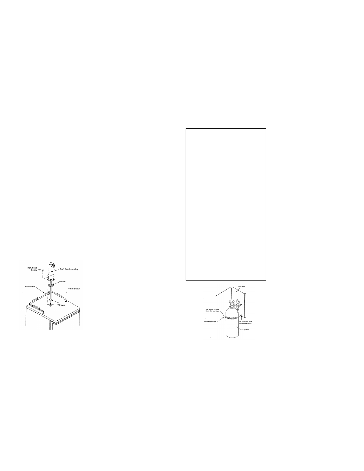
3. Install Draft Arm Assembly (See Fig. 1 ).
a. Slide gasket over wing nut on bottom of draft arm assembly
beer tube. Slide gasket up beer tube to draft arm base.
Fig. 1
b. Push wingnut and beer tube of draft arm assembly through
hole in top of cabinet until draft arm is resting on cabinet
top.
c. Align holes in draft arm base with holes in gasket and pilot
holes in cabinet top, then secure draft arm to cabinet top
with four hex head screws (5mm dia x 15mm).
4. Install Guard Rail (See Fig. 1).
a. Place guard rail on cabinet top and secure guard rail with
eight small screws.
INSTALLATION
1. Install beer dispenser on strong level floor. Avoid direct sun-
light, heat sources and moisture. This beer cooler is designed
to be FREE STANDING, the appliance is to be installed so
that the coils on the back of the unit are at least 4" away from
the wall, 4” on both sides, 4” at the top and the cabinet bot-
tom at least 3/4" to 1" from the floor.
2. Connect to 120V, 60Hz, 15 Amp grounded AC outlet. Do not
use extension cord. Use three-prong plug with three-prong
grounded wall outlet.
WARNING: Unless the above grounding method is followed,
you are not protected against severe or lethal shock in the
event of a short circuit of an electrical component or wiring of
beer dispenser.
TEMPERATURE CONTROL
1. Control is located on rear. First set the control at NORMAL
position. Wait for 24 hours to check the temperature then
adjust temperature control, if needed.
DEFROST
1. Beer dispenser will not require much defrosting since the
door opening is at a minimum. Defrost when ¼ inch frost is
built up on the cold plate. The best time to defrost is when the
keg is changed. To defrost, set temperature control at OFF
position and leave door open until ice melts. Defrost water will
accumulate at the bottom of interior cabinet which can be
absorbed with a sponge or towel. Do not use heating de-
vices or sharp objects to speed defrosting as this could
damage cabinet liner of cold plate. Reset temperature con-
trol after defrosting is completed.
INSTALLATION OF BEER SYSTEM
1. Installing CO2 Cylinder and CO2 Regulator
WARNING: CO2 GAS CAN BE DANGEROUS
a. Your CO2 cylinder is shipped empty to avoid any possible
accident during transportation. When you purchase the first
keg of beer, get CO2 cylinder filled by your beer distributor.
NOTE: Shutoff valve on CO2 cylinder may be different in
shape. Do not open shutoff valve until pressure tube, keg
tapper and beer keg are connected to CO2 regulator.
OPERATING INSTRUCTIONS FOR CO2 CYLINDERS
Do not operate valve control unless cylinder is completely
installed and connected.
TURN HANDWHEEL FULLY COUNTERCLOCKWISE AS
FAR AS IT WILL GO
IMPORTANT: If valve is not fully opened the stem may not
seal properly against the upper packing washer and the valve
may leak. If leak occurs when fully opened, tighten down
packing nut under hand wheel then open and close valve fully
several times. Replacement packing washer must be ordered
directly from valve manufacturer whose name is stamped on
valve.
PRESSURE VESSEL
 Do not remove valve from CO2 cylinder.
 CO2 cylinder should be handled only by trained, experi-
enced personnel and in accordance with the safe handling
practices recommended by the current C.G.A. pamphlet
P-1 *.
 Keep out of reach of children.
 Visually inspect monthly or more frequently. If cylinder
shows evidence of corrosion or mechanical damage, it should
be inspected and tested in accordance with the current
C.G.A. pamphlets C-1* or C-6* or it should be replaced.
CHARGE ONLY WITH DRY CARBON DIOXIDE
 Do not charge with carbon dioxide unless the pressure rat-
ing stamped on CO2 cylinder is 1800 PSI or greater.
 When charged with carbon dioxide do not exceed a fill den-
sity of 68%. (fill density is a percent ratio of the weight of gas
in the cylinder to the weight of water that the cylinder will hold
at 60°F).
 If cylinder has been exposed to temperatures in excess of
350°F, it must be destroyed.
Improper use of cylinder could cause serious bodily injury or
property damage.
C.G.A. pamphlets are published by the Compressed Gas
Association, 500th Ave., New York, N.Y.
Fig. 2
b. Connect pressure tube (clear plastic tube) to CO2 regulator
at nipple. Secure connection with hose clamp. To do this,
place hose clamp over tube and squeeze both ends of hose
clamp so that locking teeth will mate.
c. Place CO2 cylinder at right rear corner inside beer dis-
penser cabinet in upright position. Fasten CO2 cylinder with
CO2 cylinder retainer (spring) provided. Hook both ends of
retainer to holes in cold plate. (See Fig. 2).
WARNING: To avoid personal injury and/or property dam-
age, always secure CO2 cylinder with retainer to prevent it
from falling. Should CO2 cylinder valve become accidentally
damaged or broken off, CO2 cylinder can become an un-
guided missile.
2. Installing Keg Tapper and Beer Keg.
a. The Sankey type keg tapper supplied with beer dis-
penser is the most widely used in the United States.
However, some other type keg tappers, such as Gold-
en-Gate, European Sankey or Hoff-Stevens are still
being used. Before installing keg tapper, check with
your beer distributor to make sure that the Sankey type
keg tapper can be used. If you need a keg tapper other
than Sankey type, it is recommended to purchase the
tapper you need from your beer distributor keeping the
Sankey type keg tapper for future use because the
Sankey system is becoming more widely used.
If you wish to have the Sankey type keg tapper exchanged with
another type keg tapper, please return collect the Sankey type
keg tapper to the address below specifying the type of keg tapper
you need.
Panasonic Appliances Refrigeration Systems Corporation of America
2055 Sanyo Avenue
San Diego, California 92154
ATTN.: Customer Service Dept.
b. Make sure shutoff valve on CO2 regulator is in closed
position. Connect pressure tube to nipple of keg tapper
(use hose clamp). Connect beer tube from draft arm to
keg tapper (fasten securely with washer and wingnut).
c. Make sure that beer faucet and keg tapper are in
closed position, then tap a keg. Open keg tapper valve.
d. Make sure the keg is properly tapped, then open
shutoff valve on CO2 regulator. To install beer keg into
cabinet follow the steps below (See Fig. 3).
 Wet the surface of keg supports (plastic
plates).
 Lean keg supports on the front bottom edge
of cabinet. Place keg on supports supporting
keg by hands.
 Push the upper part of keg to stand in up-
right position then slide keg supports into
cabinet.
 Make sure that keg and beer tube do not
touch cold plate and that keg and keg sup-
ports are properly positioned not to interfere
with door closing.
e. Release air caught in draft arm assembly by opening
beer faucet unit foam appears. Now dispenser is ready
to use.

This manual suits for next models

1

Other Summit Kitchen Appliance manuals

Summit SBC678OS User manual

Summit

Summit SBC678OS User manual

Summit C-60 Guide

Summit

Summit C-60 Guide

Summit C-39 Guide

Summit

Summit C-39 Guide

Summit COOL1D User manual

Summit

Summit COOL1D User manual

Summit SMS1002 User manual

Summit

Summit SMS1002 User manual

Summit SCR114L User manual

Summit

Summit SCR114L User manual

Summit SCR1841BCSS User manual

Summit

Summit SCR1841BCSS User manual

Summit AL57G User manual

Summit

Summit AL57G User manual

Summit CLASSIC CL242WBV User manual

Summit

Summit CLASSIC CL242WBV User manual

Summit C48EL User manual

Summit

Summit C48EL User manual

Summit C30ELBK User manual

Summit

Summit C30ELBK User manual

Summit SCR2466 User manual

Summit

Summit SCR2466 User manual

Summit SWC532BLBIST User manual

Summit

Summit SWC532BLBIST User manual

Summit MB24L User manual

Summit

Summit MB24L User manual

Summit SBC583SS User manual

Summit

Summit SBC583SS User manual

Summit SBC490 User manual

Summit

Summit SBC490 User manual

Summit ALFD24WBV User manual

Summit

Summit ALFD24WBV User manual

Summit SBC4907FRTWIN User manual

Summit

Summit SBC4907FRTWIN User manual

Summit ASDG2411 User manual

Summit

Summit ASDG2411 User manual

Summit SBC677BIIFTWIN User manual

Summit

Summit SBC677BIIFTWIN User manual

Summit SBC500BST Guide

Summit

Summit SBC500BST Guide

Summit SWC530LBISTCSS User manual

Summit

Summit SWC530LBISTCSS User manual

Summit SBC490BI User manual

Summit

Summit SBC490BI User manual

Summit STC6 User manual

Summit

Summit STC6 User manual

Popular Kitchen Appliance manuals by other brands

Bourgini 22.6392.00.00 instructions

Bourgini

Bourgini 22.6392.00.00 instructions

IMC IMC-2000BX Operation manual

IMC

IMC IMC-2000BX Operation manual

Hottek HT-977-001 user manual

Hottek

Hottek HT-977-001 user manual

Domo DO9056C Instruction booklet

Domo

Domo DO9056C Instruction booklet

Melissa 643-049 instructions

Melissa

Melissa 643-049 instructions

NOVO NOVO15WINE1 Installation instructions & owner's manual

NOVO

NOVO NOVO15WINE1 Installation instructions & owner's manual

Vinotemp Element EL-168GFEB owner's manual

Vinotemp

Vinotemp Element EL-168GFEB owner's manual

Ezcuisine AirGO AP360 Cooking guide

Ezcuisine

Ezcuisine AirGO AP360 Cooking guide

PROMARKS Promax DC-640 Operation manual

PROMARKS

PROMARKS Promax DC-640 Operation manual

Baumatic BT3062SS user manual

Baumatic

Baumatic BT3062SS user manual

Zyliss 31500 manual

Zyliss

Zyliss 31500 manual

Eldom Stim DA100 Operating	 instruction

Eldom

Eldom Stim DA100 Operating instruction

Thermos SP400 Smart Lid user manual

Thermos

Thermos SP400 Smart Lid user manual

Euromaid EWC171IB user manual

Euromaid

Euromaid EWC171IB user manual

Princess NICE PRICE SANDWICH MAKER Instructions for use

Princess

Princess NICE PRICE SANDWICH MAKER Instructions for use

Wartmann WM-2110 DH user manual

Wartmann

Wartmann WM-2110 DH user manual

SEVERIN SM 3726 Dimensions

SEVERIN

SEVERIN SM 3726 Dimensions

Bosch NGM5056UC use and care manual

Bosch

Bosch NGM5056UC use and care manual

manuals.online logo
manuals.online logoBrands
  • About & Mission
  • Contact us
  • Privacy Policy
  • Terms and Conditions

Copyright 2025 Manuals.Online. All Rights Reserved.