19
SR 580 Helmet with Visor
1. General information
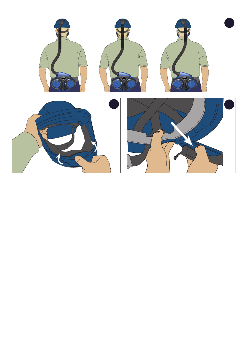
SR 580 together with the fan unit SR 500/SR 500 EX/SR 700
and approved filters is included in the Sundström fan-assisted
respiratory protective device system conforming to EN 12941/
EN 12942:1998 (fig. 2). SR 580 can be used together with fan
unit SR 500 EX in explosive atmospheres.
The breathing hose must be connected to the fan unit equipped
with filters. The above atmospheric pressure generated in the
head-top prevents particles and other pollutants from being
admitted into the breathing zone.
SR 580 can also be used together with compressed air
attachment SR 507 (fig. 1). This combination forms a breathing
apparatus designed for continuous air flow, for connection to
a compressed air supply in accordance with EN 14594:2005.
If you have any questions regarding the selection and mainte-
nance of equipment, consult your work supervisor or get in touch
with the sales outlet. You can also contact the Sundström Safety
AB’s Technical Support department. Respiratory protection
must always be part of a respiratory protection programme.
Forinformationandguidance,seeEN529:2005.
This standard provides information about the important aspects
of a respiratory protection programme, but does not replace
national or local regulations.
1.1 Applications
The SR 580 together with fan SR 500/SR 500 EX/SR 700
or SR 507 compressed air attachment can be used as an
alternative to filter respirators in all situations in which these are
recommended. This applies particularly to work that is hard,
warm or of long duration. When selecting the head top, some
of the factors that must be taken in to account are as follows:
• Typeofpollutants
• Concentrations
• Workintensity
• Protectionrequirementsinadditiontorespiratoryprotective
device.
The helmet must only be used when carrying out work it is
intended for. It provides limited protection by reducing the
force of falling objects that strike or penetrate the top of the
helmet shell.
The risk analysis should be carried by a person who has
suitable training and experience in the area.
1.2 Warnings/limitations
Warnings
The equipment must not be used
• ifthesurroundingairdoesnothavenormaloxygen
content,
• ifthepollutantsareunknown,
• inenvironmentsthatareimmediatelydangeroustolifeand
health(IDLH),
• withoxygenoroxygen-enrichedair,
• ifyoufinditdifficulttobreathe,
• ifyousmellortastepollutants,
• ifyouexperiencedizziness,nauseaorotherdiscomfort.
Materials that come into contact with the skin of sensitive
people may cause allergic reactions.
Damaged or scratched occulars must immediately be replaced.
Eye-protectors against high-speed particles worn over stan-
dard ophthalmic spectacles may transmit impacts, thus
creating a hazard to the wearer.
Limitations
• Thehead-topsmustnotbeusedtogetherwithpeel-offsin
potentially explosive atmosphere.
• Iftheface seal isnotfirmly in contactwiththeface, the
pressure necessary for maintaining the correct protection
factor will not be established.
• Iftheuserisexposedtoveryhighworkintensity,apartial
vacuum may occur in the device during the inhalation phase,
which may involve the risk of leakage into the head-top.
• Theprotectionfactormaybereducediftheequipmentis
used in surroundings in which high wind speeds occur.
• Thesealofthehead-topagainstthefacemustbeassured.
This may be difficult to achieve if the user has a beard or
sideboards.
• Beawarethatthebreathinghosemightmakealoopand
get caught up by something in your surrounding.
• Neverliftorcarrytheequipmentbythebreathinghose.
• Thehelmetisnotdesignedtowithstandpenetrativeimpacts
from the front, sides or back, but can provide protection
against less severe impacts against those surfaces.
• Avoidcontactwithelectricalwiringwhenusingthehelmet.
• When gluingitems tothehelmet,only rubber or acrylic-
based adhesives may be used. The helmet must not be
painted.
2. Use
2.1 Unpacking
Check that the equipment is complete as shown on the packing
list and that it has not been damaged during transit.
2.2 Packing list
• Helmet
• Lowervisorframe
• Visor
• Faceseal
• Breathinghose
• Userinstructions
• Cleaningtissue
2.3 Assembly
Also see the user manual for the SR 500/SR 500 EX/SR 700 fan
and the SR 507 compressed air attachment, whichever is used.
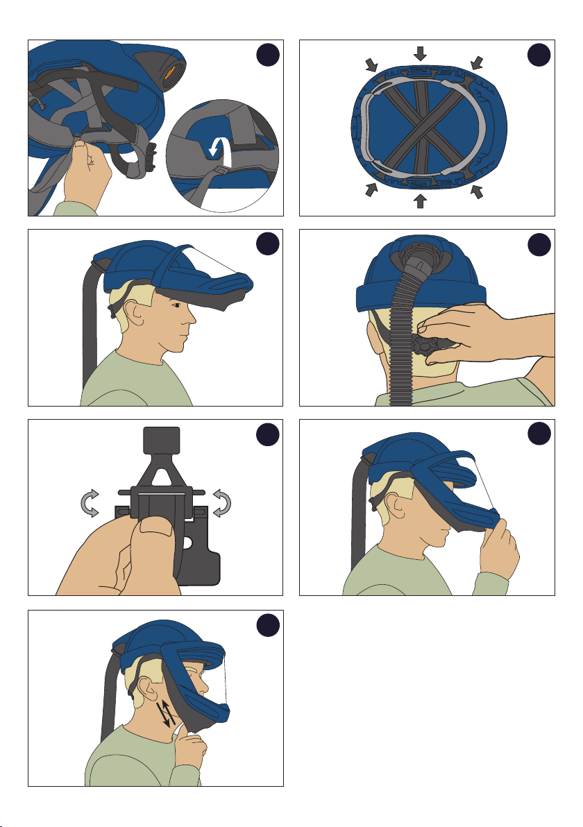
Face seal and visor
Assembly of the face seal and visor does not require any tools.
Do the following:
• Fitthefacesealontheinnerflangeinthelowervisorframe
(fig. 3). Start at one side, push the pin upwards and control
that the lip is fastened in the lower visor frame (fig. 4).
• Pushalongthefacesealframesoitissecurelyfastenedon
the lower visor frame (fig. 5). Control that the pin and lip is
fastened on both sides (fig. 4).
• Fitthevisorintothelowervisorframe.Applyingalittlewater
to the seal will make fitting easier (fig. 6).
• Fitthelowervisorframetothehelmetbyslidingitintoposi-
tion. A ‘click’ indicates that the frame is locked in position
(fig. 7a-7d).
• Checkthatthevisorhasachievedafullsealaroundtheentire
visor frame.
• Attachthehooksintheheadharness(fig.8).
EN