Sungrow EyeM4 User manual

User Manual


This manual is intended for the wireless communication module researched
and manufactured by Sungrow Power Supply Co., Ltd.
This manual is intended to provide users with detailed information on the
wireless communication module as well as installation, operation, and
maintenance description.
Related Documents
This manual may not cover all information on the wireless communication
module. For more information, visit the website at
This manual is intended for technically qualified personnel who need to install,
operate, and maintain the wireless communication module and end users who
view plant information and perform operations through the iSolarCloudAPP.

II

System Diagram
Wireless Communication Module
Product Appearance
Principle Description
Function Description
Unpacking and Inspection
Nameplate
Scope of Delivery
Storage
Installation Location
Installation
Preparation before Installation
Installation Steps
Inspection Before Commissioning
Commissioning Steps
Removal
Disposal

The qualified technical personnel can perform the following operations:
Install the wireless communication module to the inverter bottom.
Commission the wireless communication module.
Operate and maintain the wireless communication module.
Upon receiving, check whether the wireless communication module is
damaged during transport. If there is any damage, contact SUNGROW
or the forwarding company.

Risk of injury due to incorrect operations!
Always observe the instructions in this manual when moving and
placing the wireless communication module.
Incorrect operations on the wireless communication module can
cause minor injury, serious injury, or bruise.
Mechanical installation
Poor ventilation will compromise the system performance!
Ensure that the device is well ventilated and sufficiently cooled down
during operation.
Electrical connection
All electrical connections must comply with local and national
regulations.
During operation
Never remove the wireless communication module if it is running or it
carries voltage.
Danger of burning!
Never touch the hot components when the wireless communication
module is running.

Keep unauthorized persons away!
Place warning signs or labels before starting electrical connections
and maintenance, to ensure that unauthorized persons have no access
to the electrical operating area.
Restart the wireless communication module only after the faults
impairing the safety performance of the wireless communication
module have been cleared.
No serviceable components contained in the wireless
communication module. If maintenance work is required, contact
SUNGROW.
Never replace the internal components without permissions.
Otherwise, SUNGROW shall not be held liable for any damage caused.
The components can be damaged due to touching the PCB or other
components sensitive to ESD or performing incorrect operations.
Avoid unnecessary touch to the PCB.
Respect the ESD protection standards, for example, wear a wrist
strap.
Ensure that all warning labels and nameplates on the wireless
communication module are:
Clearly legible
Not removed or covered

System Diagram
The wireless communication module can obtain the inverter information and
transmit the data to the remote server. show the typical
application of the wireless communication module.
Router
Ethernet
Wireless iSolarCloud
iSolarCloud management platform
EyeM4
signal
Wireless signal
APP
Inverter
Communication accessory port
Application of the wireless communication module (WLAN)
Inverter
Communication base
station
Ethernet
APP
Wireless signal
EyeM4
Wireless signal
iSolarCloud
Remote monitoring platform
Communication accessory port
Application of the wireless communication module (4G)
Inverter
Communication base
station
Ethernet
APP
Wireless signal
EyeM4
Wireless signal
iSolarCloud
Remote monitoring platform
Communication accessory port
PC (WEB page)
Wireless signal
GPRS
WLAN
Application of the wireless communication module (4G+WLAN)

Wireless Communication Module
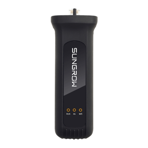
Product Appearance
1
2
Appearance
* The image shown here is for reference only. The actual product you receive
may differ.
Indicating the running state of the module
Used to connect the module with the inverter
Ensure that the wireless communication module is free of visible damages
before performing the next operations.
Principle Description
The wireless communication module can be connected to the inverter through
the standard RS485 interface, thereby obtaining inverter running data. The
running data is transmitted to the remote server in the Wi-Fi wireless
communication manner.
Function Description
The wireless communication module mainly has the following functions:
Data collection
The wireless communication module can store system information such as
running data and fault records.
Communication interface
RS485, Baud rate
Remote management of the iSolarCloud
The device can be periodically connected to the iSolarCloud server and
transmit the data to the server.

The overall installation flow of the wireless communication module is shown in
the following figure 3-1.
U n p a c k a n d c h e c k
R e a d t h e m a n u a l
I n s t a l l t h e w i r e l e s s
c o m m u n i c a t i o n m o d u l e
E l e c t r i c a l c o n n e c t i o n
I n s p e c t i o n b e f o r e
c o m m i s s i o n i n g
C o m m i s s i o n i n g
S t a r t
S t a r t ?
E n d
Troubleshooting
Y e s
N o
1
I n s t a l l ?S t o r e
2
S e l e c t i n s t a l l a t i o n l o c a t i o n
4
3
5
6
7
8
Y e s
N o
9

Description of installation flow
Read the user manual, especially, the "Safety
Instructions".
Store the wireless communication module
properly if it is not installed immediately.
Select the optimum installation site.
Install the wireless communication module.
Electrical connection.
Inspection before commissioning.
Start the wireless communication module.
Troubleshooting.

Unpacking and Inspection
The wireless communication module has been inspected and tested before
delivery, but it may be damaged during transport. Check the module carefully
upon receiving.
Check whether the packing case is damaged.
Check the scope of delivery for completeness and correctness according to
the packing list.
Check whether the device in the packing case is intact and is free of
damage.
If there any damage, contact the forwarding company or SUNGROW. Take a
picture of the damage, with which we can provide quicker service.
Do not dispose of the packing case. It is recommended to store the wireless
communication module in its original packing case.
Nameplate
The nameplate is attached to the side of the wireless communication module,
including information such as product model and manufacturer.
,

( )
Scope of Delivery
B
A
Upload inverter data
Quick installation guide
Storage
Store the wireless communication module in proper environment if it is not
installed immediately. If otherwise, the wireless communication module may be
rusted or its internal components may be damaged, and SUNGROW shall not
be held liable for any damage caused.
The wireless communication module must be packed in its original packing
case with desiccant kept inside.
The packing case must be sealed with adhesive tape.
The wireless communication module must be stored in a clean and dry place
with dustproof and waterproof measures taken.
The storage temperature ranges from –40°C to 85°C ;and the relative
humidity ranges from to
The wireless communication module must be stored in a place away from
chemically corrosive materials.

Installation Location
The wireless communication module is installed at the inverter bottom.
With ingress of protection IP66, the wireless
communication module can be installed both
indoors and outdoors.
The ambient temperature ranges from –30°C
°C
The permissible relative humidity is –
Max. ambient
temperature:
+60°C
Min. ambient
temperature:
-30°C
Max. relative
humidity: 95%
(non-condensing)
Installation
Preparation before Installation
Adapter inverter: single-phase residential inverter and three-phase string
inverter manufactured by SUNGROW.
The inverter has been installed correctly and the DC side can be powered on
(For details, refer to the corresponding user manual.).
Installation Steps
Take out the wireless communication module from the packing case, and
identify the correct connection manner.

Insert the wireless communication module into the network port (COM)
at the bottom of the inverter until it snaps into place with a "Click" sound.
If the module is still loose, remove it from the communication port and
check whether the port is damaged. If the port the normal, reinsert the
wireless communication module.
The wireless communication module can be plugged in and out
without switching off the inverter.
If you need to collect information of several inverters, connect the
inverters in the daisy chain manner through the RS485 communication
cables as described in the corresponding user manual.
Inverter 1
RS485 Inverter 2 Inverter n(n≤10)
RS485 RS485
Multiple inverters in daisy chain
Shielding layer is grounded
Com.
After installation, the wireless communication module will automatically
communicate with the inverter once the inverter is powered on.
Press down the buckles on both sides when plugging/unplugging
the module. Frequent plugging/unplugging operation is not
recommended.
•If the wireless communication module needs to be replaced
during operation, replace it via the iSolarCloud App (For details,
refer to the user manual of the iSolarCloudAPP.).

Inspection Before Commissioning
Check the following items before
Environment inspection
The wireless communication module is installed in a place convenient for
operation and maintenance.
Ensure again that the wireless communication module is firmly in place.
The installation environment is well-ventilated.
The wireless communication module is correctly connected to the
inverter.
The cables are appropriately routed and well protected against
mechanical damage.
Make sure the inverter to be connected has a correct SN number
(product serial number).
Commissioning Steps
When all the foregoing items meet requirements, start the wireless
communication module for the first time.
Connect the AC circuit breakers.
Connect the DC switches of the inverter.
If the sunlight is sufficient, the PV panel starts to supply DC power to the
inverter. When the DC voltage exceeds the start voltage of the inverter,
the inverter will automatically start.
Wait about 15s for the wireless communication module to start
automatically.
Download the iSolarCloud APP and configure the parameters of the
inverter connected with the wireless communication module. For details,
refer to the corresponding quick operation guide.
Table of contents
Other Sungrow Control Unit manuals
Popular Control Unit manuals by other brands

MHD
MHD OBD2 user manual

Jetter
Jetter JX3-DMS2 Installation instruction

Flexball
Flexball Series 3500 Operating manual & installation guide

Cumberland
Cumberland Var-O-Matic installation instructions

IBASE Technology
IBASE Technology ET977 user manual

STIEBEL ELTRON
STIEBEL ELTRON SOKI 7 E plus Operation and installation

TECHCON SYSTEMS
TECHCON SYSTEMS TS5624DMP user guide

Pfeiffer Vacuum
Pfeiffer Vacuum HPU 001 operating instructions

Leuze electronic
Leuze electronic MSI 200 Series user manual

iRangex
iRangex RX4 manual

Mesto
Mesto Neles XH Series Installation maintenance and operating instructions

Mitsubishi
Mitsubishi MELSEC-A AJ71DN91 user manual