manuals.online logo
Brands
  1. Home
  2. •
  3. Brands
  4. •
  5. Sunlight Supply
  6. •
  7. Controllers
  8. •
  9. Sunlight Supply Titan Controls Atlas 4 User manual

Sunlight Supply Titan Controls Atlas 4 User manual

Atlas 4TM
Dual Zone CO2 Controller
Instruction Manual
VANCOUVER, WASHINGTON U.S.A.
www.titancontrols.net
®
VANCOUVER, WASHINGTON U.S.A.
www.titancontrols.net
Notes:
_________________________________________________
_________________________________________________
_________________________________________________
_________________________________________________
_________________________________________________
_________________________________________________
________________________________________________
1 Square = 1 Foot
Step 1: Connecting the Equipment
Step 2: Time Setting
Step 3: Zone Selection
Place the Controller on a wall in the
most convenient location. Locate
one sensor in each growing room,
in a place presenting the average
plant conditions and protecting the
enclosure from light bulbs, heat
sources, spray and condensation.
Sensor must be hanged from the
ceiling with the included cable, tied
to the enclosure flanges as shown
: it is important to direct the sensor
connector toward the floor.
Note : The sensors have light de-
tectors on both sides, allowing
them to be placed along the walls.
1. Controller
2. Output box
3. Sensor
4. Power supply
5. Network cable
6. Telephone cable
New units will require the user to enter the time. See Time
Setting on page 4 and begin at Step 5.
Turn knob only (do not press) to select zone #1 or #2 or to
view the time. The indicator for the selected zone remains lit at
all times, except when the time is displayed.
WARRANTY SERVICE: Please read warranty information first
If after reviewing the troubleshooting tips the unit will still not work, you should return it to the
Dealer where you purchased the controller. They will be able to further evaluate the unit and test its
various components and quite possibly will be able to identify and/or fix any problems. If the Dealer
is unable to fix the unit, they will return it to us for factory repair.
If there are no Dealers in your area, you may contact us directly for technical support. If we cannot
help you resolve the problem over the phone, we will issue you a RMA # (return merchandise
authorization) authorizing you to return the unit to us for factory reconditioning (if the unit is under
warranty). Contact the number below for a RMA and shipping address. Complete the form below
and include it with your unit. Also please write the RMA # on the outside of the box.
Please package the unit in its original packaging. If it is damaged in shipment we cannot be
responsible.
Once we receive the unit back, we will repair or replace the controller within 48 hours (business)
and return it to you freight prepaid via FedEx or UPS ground shipment.
Include the following if returning directly to Titan Controls
• Proof of purchase • This completed form • RMA # on the outside of the box
Return Merchandise Authorization Number (Required
Company Name: ____________________________________________________________________________________
Contact Name: _____________________________________________________________________________________
Address: __________________________________________________________________________________________
____________________________________________________________________________________________________
Phone #: ___________________________________________________________________________________________
Email address: _______________________________________________________________________________
What is the nature of the problem? _________________________________
____________________________________________________
____________________________________________________
____________________________________________________
____________________________________________________
____________________________________________________
____________________________________
Send to your nearest location – shipping address will be given when the RMA # is issued:
www.titancontrols.net
For technical assistance call us at 1-888-80-Titan or 1-888-808-4826.
®
Step 4: Setting high value
Step 5: Setting low value
Step 6: 24 hour log
Sensor calibration and hour setting
Click knob and turn to set high ppm value of
selected zone. This is the maximum CO2 level
the generator will allow. In fact, the generator will
usually stop before reaching this level in order to
avoid overshoots.
Click knob and turn to set low ppm value of selected
zone. This is the minimum CO2 level the generator
will allow. In fact, the generator will usually turn on be-
fore reaching this level in order to avoid undershoots.
Click knob and turn to select log time
among last 24 hours; controller displays
the min., average and max. ppm read-
ings observed during the selected hour,
for each zone separately.
WARNING
Sensor calibration is not required for a new unit (factory calibrated).
Verify CO2 sensor precision by exposing your unit to outdoor air every 6 months (correct value stands
between 350 and 450 ppm). To calibrate your sensor, refer to Appendix 2. Hour can be set at all times;
also refer to Appendix 2.
Appendix 2
Calibration of CO2 sensor
Important Notice : This step is not required for a new unit (factory calibrated).Verify
CO2 sensor precision by exposing your unit to outdoor air every 6 months (cor-
rect value stands between 300 and 500 ppm). If you need to calibrate the sensor,
please follow these instructions. At any time before the last step, the calibration
procedure can be cancelled, causing the controller to return to normal operation.
WARNING EACH ZONE SENSOR MUST BE CALIBRATED SEPARATELY
1. IS CALIBRATION NEEDED? First select zone #1 or #2,
then expose the correspponding remote sensor to outdoor
air for a minimum of 5 minutes, fresh air being used as a
reference. If the value on screen is around 350 to 450 ppm,
YOU DO NOT NEED TO RECALIBRATE THE SENSOR OF
THIS ZONE.
2. CALIBRATION IS NEEDED : Click knob repeatedly until
“Calibration” indicator turns ON.
3. Press knob and keep it pressed for about 5 seconds, until
light indicator begins to flash and “CAL“ appears on screen.
4. Let button go, “CO2 CAL“ appears on screen, click knob
again, then 400 will appear on screen to remind you that
you need to place the unit in fresh air before starting the
calibration. If your controller is not in fresh air condition, just
click knob to abort calibration.
5. STARTING CALIBRATION : press knob and keep it pressed
for at least 5 seconds, until “CAL” shows up on screen,
then let button go.
6. Automatic calibration will take a few seconds to complete:
“CAL good“ will appear on screen for 5 seconds, and con-
troller will return to normal operation automatically.
Calibration
Calibration
Time setting
Follow these instructions
1. View current time by turning knob fully clockwise
2. Click knob until << CALIBRATION >> indicator turns on
3. Press knob for 5 seconds until CAL appears on screen
4. Let knob go, you now enter the time setting mode
5. Click knob to display current time. You must turn knob
to set minutes before going to step 6
6. Click knob and turn to set hours. Click knob to toggle
between hours and minutes
7. Press knob for 5 seconds until GOOD
appears on screen
8. Let knob go to return to normal operation

Step 7: Setting operating mode
Click knob and turn to select your
Control Mode for each zone.
For set –up using two burners
F11: CO2 enrichment – day only
F12: CO2 enrichment – night only
F13: CO2 enrichment – day & night
F14: CO2 exhausting – day only
F15: CO2 exhausting – night only
F16: CO2 exhausting – day & night
For set – up using one burner (see
Appendix 1)
F17: CO2 enrichment, day only,
Click knob to return to CO2 display
PARAMETER SETTING IS NOW COMPLETE, YOUR CONTROLLER IS READY TO USE
Appendix 1
Set-up Mode F17, using
a damper with actuator
Plug the CO2 generator
and fan into Output Box
#1 and the flap switch
into the Output Box #2.
Make sure the airflow is
directed toward Room
#1 when the flap switch
is de-activated.
1. Controller
2. Output box
3. Sensor / Sensor
4. Power supply
5. Network cable
6. Telephone cable
Set-up Mode F17, using ventilation fans and an ON-OFF Switcher
(OSW –sold separately)
• Plug the CO2 generator into the upper outlet of Output Box #1.
• Plug the ON-OFF switcher (OSW) into the lower outlet of Output Box #1.
• Plug the Room #1 Fan into the ON output (OSW upper outlet) .
• Plug the Room #2 Fan into the OFF output (OSW lower outlet).
• Finally, plug the OSW sense cord into the Output Box #2.
1. Controller
2. Output box
3. Sensor
4. Power supply
5. Network cable
6. Telephone cable

Other Sunlight Supply Controllers manuals

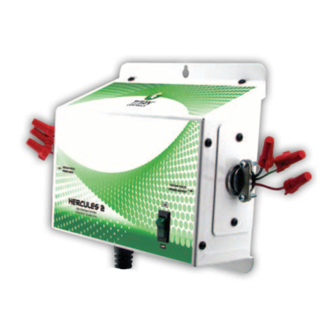
Sunlight Supply TITAN CONTROLS HERCULES 2 User manual

Sunlight Supply

Sunlight Supply TITAN CONTROLS HERCULES 2 User manual

Sunlight Supply TITAN CONTROLS HELIOS 8 User manual

Sunlight Supply

Sunlight Supply TITAN CONTROLS HELIOS 8 User manual

Sunlight Supply TITAN CONTROLS KRONUS 2 User manual

Sunlight Supply

Sunlight Supply TITAN CONTROLS KRONUS 2 User manual

Sunlight Supply TITAN CONTROLS Helios 5 User manual

Sunlight Supply

Sunlight Supply TITAN CONTROLS Helios 5 User manual

Sunlight Supply TITAN CONTROLS ZEPHYR 3 User manual

Sunlight Supply

Sunlight Supply TITAN CONTROLS ZEPHYR 3 User manual

Sunlight Supply Sun System 1 User manual

Sunlight Supply

Sunlight Supply Sun System 1 User manual

Sunlight Supply Titan Controls Helios 1 User manual

Sunlight Supply

Sunlight Supply Titan Controls Helios 1 User manual

Sunlight Supply Titan Controls Helios 2 User manual

Sunlight Supply

Sunlight Supply Titan Controls Helios 2 User manual

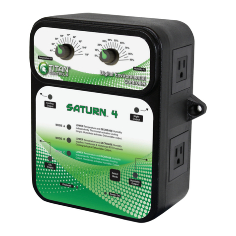
Sunlight Supply TITAN Controls Saturn 4 User manual

Sunlight Supply

Sunlight Supply TITAN Controls Saturn 4 User manual

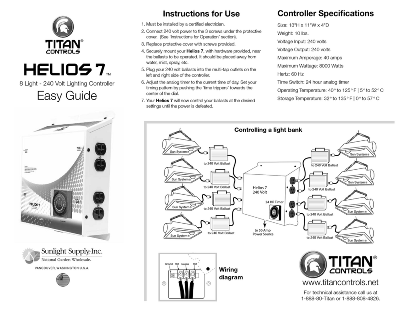
Sunlight Supply Titan Controls Helios 7 Product information sheet

Sunlight Supply

Sunlight Supply Titan Controls Helios 7 Product information sheet

Sunlight Supply TITAN CONTROLS HELIOS 8 Product information sheet

Sunlight Supply

Sunlight Supply TITAN CONTROLS HELIOS 8 Product information sheet

Popular Controllers manuals by other brands

GreenFlux T2235-02 installation manual

GreenFlux

GreenFlux T2235-02 installation manual

AGELKOM CAP04 manual

AGELKOM

AGELKOM CAP04 manual

Mitsubishi Q2ACPU user manual

Mitsubishi

Mitsubishi Q2ACPU user manual

Botex DMX DC-1224 user manual

Botex

Botex DMX DC-1224 user manual

Hydrofarm Autopilot PX1 instructions

Hydrofarm

Hydrofarm Autopilot PX1 instructions

Seagull REC2 user manual

Seagull

Seagull REC2 user manual

Panasonic AW-RP605AN operating instructions

Panasonic

Panasonic AW-RP605AN operating instructions

Leroy-Somer AVR R448 instruction manual

Leroy-Somer

Leroy-Somer AVR R448 instruction manual

TM Technologie MCL quick start guide

TM Technologie

TM Technologie MCL quick start guide

Doli EDC 120 Assembly instruction

Doli

Doli EDC 120 Assembly instruction

Leviton Acenti ACF01-1L installation instructions

Leviton

Leviton Acenti ACF01-1L installation instructions

MOVETEC MCP-TDH6 user guide

MOVETEC

MOVETEC MCP-TDH6 user guide

Inficon VGC031 operating manual

Inficon

Inficon VGC031 operating manual

Matelec FPC-12725 Owner's operation manual

Matelec

Matelec FPC-12725 Owner's operation manual

Allen-Bradley PowerFlex 525 user manual

Allen-Bradley

Allen-Bradley PowerFlex 525 user manual

Siemens Simatic S7-1500 Function manual

Siemens

Siemens Simatic S7-1500 Function manual

ENDA EDT3011 Series manual

ENDA

ENDA EDT3011 Series manual

Danfoss EKC 202B manual

Danfoss

Danfoss EKC 202B manual

manuals.online logo
manuals.online logoBrands
  • About & Mission
  • Contact us
  • Privacy Policy
  • Terms and Conditions

Copyright 2025 Manuals.Online. All Rights Reserved.