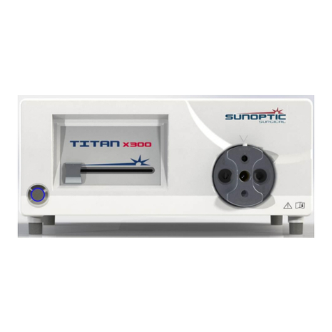
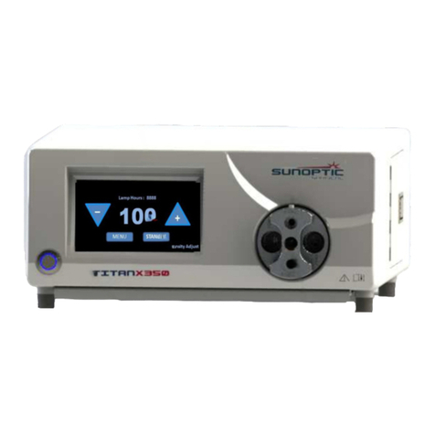
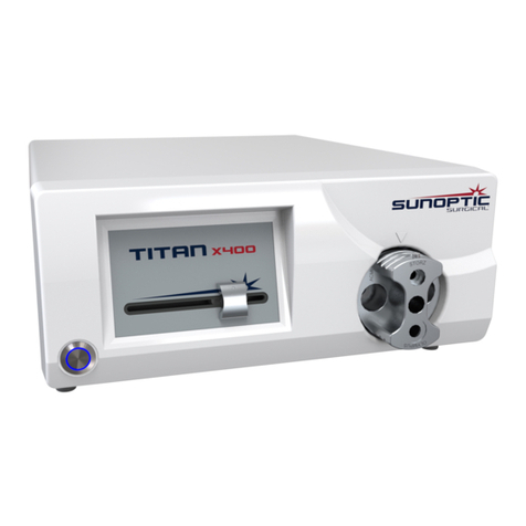
Sunoptic Surgical HDC-300C User manual

LIT-239 SUNOPTIC SURGICAL®
Rev. A (English)
Page 1 of 21
HDC-300C
Titan HD Camera
Instructions for Use
Version 1.0
Sunoptic Technologies
®
6018 Bowdendale Avenue
Jacksonville, FL 32216 USA
Customer Service: 904 737 7611
Toll Free 877 677 2832
EC|REP AJW Technology Consulting GmbH
Königsallee 106
40215 Düsseldorf, Germany
+49 (0) 211 3013 2232

LIT-239 SUNOPTIC SURGICAL®
Rev. A (English)
Page 2 of 21
TABLE OF CONTENTS
1. INTRODUCTION
1.1 INDICATIONS FOR USE
1.2 FUNCTION OF DESIGN
1.3 SPECIFICATIONS
1.4 CLASSIFICATIONS
2. GENERAL WARNINGS
3. PRODUCT OVERVIEW
3.1 THE CAMERA CONSOLE
3.2 THE CAMERA HEAD
3.3 COMPATIBLE ACCESSORIES
4. SETUP AND INTERCONNECTION
4.1 SETTING UP THE CONSOLE
4.2 CONNECTING THE CAMERA
4.3 CONNECTING MONITORS
4.4 CONNECTING AC POWER
4.5 POWERING ON THE UNIT
4.6 TURNING OFF THE UNIT
5. OPERATION
5.1 USING THE CONSOLE TOUCH SCREEN INTERFACE
5.2 ENTER PATIENT DATA
5.3 REVIEW/PLAY CASES
5.4 RECORD
5.5 SETTINGS
5.6 MAIN MENU
5.7 KEYBOARD CONTROLS
5.8 FOOTSWITCH
5.9 FAULT DISPLAYS
6. CLEANING AND DISINFECTION
7. MAINTENANCE, SERVICING & REPAIR, WARRANTY
7.1 USER SERVICE AND MAINTENANCE
7.2 LIMITED WARRANTY
7.3 REPAIR
8. END OF PRODUCT LIFE
9. SYMBOLOGY

LIT-239 SUNOPTIC SURGICAL®
Rev. A (English)
Page 3 of 21
1. INTRODUCTION
Congratulations on the purchase of your new HD Camera System!
The Sunoptic Technologies High Definition Camera System is a head-mounted surgical camera
used to capture still and video images of surgical procedures.
You have chosen the best and we would like to make sure you receive optimal results with your
new Camera System by using it correctly.
This Operator Manual will help you to install, operate and clean the Camera System. It will give
you maintenance and service guidelines as well as recommendations for best performance
results.
Federal law (United States of America) restricts this device to use by, or on the order
of, a physician.
1.1. INDICATIONS FOR USE
The intended use of this device is to display, record and play back surgical procedures. As
such, this device is not intended to diagnose, prevent, monitor, treat or alleviate disease,
injuries or handicaps, nor for the investigation, replacement or modification of the anatomy or of
a physiological process, and is not to be used with or as an endoscope or related system. As
such, this device has no essential performance in accordance with IEC 60601 and users are
advised that should this system fail to operate, suitable backup systems be available for any
procedure in which this device may be used.
There are no known contraindications.
The HD Camera is intended to be used in a controlled operating room environment with
compatible devices by qualified medical personnel. The camera system and head is provided
non-sterile. The system has a 3 year expected service life.
1.2. FUNCTION OF DESIGN
The HD Camera System incorporates a remote camera head which captures an image as
presented with a coupled light source and displays this image onto a viewing monitor. Displayed
images and videos may be captured and stored internally or transferred or transmitted via a
variety of means, controlled through the device’s integrated touch panel.

LIT-239 SUNOPTIC SURGICAL®
Rev. A (English)
Page 4 of 21
1.3. SPECIFICATIONS
PARAMETER VALUE
Power Requirements
Voltage: 90-240VAC
Frequency: 47-31Hz
Power: 100VAC/2.9A 240VAC/1.27A
Video Outputs
2x HDMI
2x DVI
Connectivity 5 x USB 2.0 ports
2 x Ethernet ports
2 x Camera Inputs (Rear
Camera Input Optional)
1 x Footswitch Input
Internal Storage
(Typical)
12Mbps = 90 hours
18Mbps = 60 hours
24Mbps = 45 hours
CCU Dimensions 13”W x 15.25”L x 5.25”T
CCU Weight 16.0 lbs
Camera Weight 0.85lbs
Transport & Storage
Conditions
-40 to 122
⁰
F (-40 to 50
⁰
C)
10 to 90%, non-condensing
Operating Conditions 50 to 86
⁰
F (10 to 30
⁰
C)
30 o 75% RH, non-condensing
1.4 CLASSIFICATIONS
PARAMETER VALUE
System Classification
FDA Class I
EU Class I
Health Canada Class I
Design Criteria IEC 60601-1 Ed. 3.1 : 2012
EMC Certifications CISPR 11 Class B
IEC 60601-1-2 Ed. 4
CE Marking CE Marking for MDD 93/42/EEC
According to protection
against electric shock. Class I [grounded]
According to Degree of
protection against harmful
ingress of water
Camera Control Units are Ordinary [IPX-0] no
protection.
According to the degree of
safety in the presence of
Flammable Anesthetics
Equipment is NOT suitable for use in the presence of
flammable anesthetics.
According to the mode of
operation Continuous

LIT-239 SUNOPTIC SURGICAL®
Rev. A (English)
Page 5 of 21
2. GENERAL WARNINGS
Use of this equipment may present hazards to the user and/or end patient. Before operating this
device, please read this operating manual thoroughly and follow all warnings, cautions, and
instructions for use. The words warning, caution, and note carry special meaning and should be
carefully reviewed:
Warning: Indicates risks to the safety of the patient or user. Failure to follow warnings may result
in injury to the patient or user.
Caution: Indicates risks of improper use and/or damage to the equipment. Failure to follow
cautions may result in loss of function or product damage.
Note: Indicates special information to clarify instructions or present additional useful information.
An exclamation mark within a triangle is intended to alert the user to the presence of important
operating and maintenance instructions in the manual.
Warnings
To avoid potential serious injury to the user, patient, and/or damage to this device, please
note the following warnings:
1. Failure to follow instructions in this manual may lead to serious injury or damage to
the equipment. Read this operating manual thoroughly, especially the warnings,
and be familiar with its contents before using this equipment.
2. This equipment is designed to be used by a qualified physician, having complete
knowledge of the use of this equipment and the procedure to be performed.
3. This equipment should be installed and tested prior to use. A pre-operative check
should be performed prior to administration of patient anesthesia to ensure all
desired functions are operational, that a viable surgical image is being displayed on
the monitor, and there are no signs of damage to the equipment.
4. For the protection of the patient, it is recommended to have a back-up system
ready for use in the event of primary equipment failure.
5. This equipment may present a risk of electric shock. To reduce this risk, this
equipment must only be connected to a supply mains with protective earth.
6. In the case of equipment failure, this equipment may draw excessive power from
the supply circuit and interrupt service to other equipment powered by the same
circuit. To reduce this risk, this equipment should not share the same electrical
outlet or grounding with life support or life sustaining equipment.
7. An uninteruptable power supply is recommended.
8. Always set up the console in a location that allows adequate ventilation (airflow) to
the console. Insufficient ventilation may cause the console to overheat and shut
down and create risk of fire. Always set up the console to position the appliance
inlet (where the power cord attaches to the equipment) so that it is readily
accessible.
9. Use only the provided medical grade power cord and replacement fuses specified
by the manufacturer to reduce risk of harm resulting from fire or interruption of

LIT-239 SUNOPTIC SURGICAL®
Rev. A (English)
Page 6 of 21
mains circuit. Follow the instructions provided herein and always remove power
from the device prior to inspection or replacement of fuses.
10. Use only manufacturer’s specified compatible accessories and peripheral
equipment. Use of non-approved equipment may cause loss of function.
11. Before each use, check the outer surface of this equipment to be used to ensure
that there are no rough surfaces, sharp edges, or protrusions that can cause injury.
12. Avoid dropping the camera system or rough handling. The camera system contains
sensitive components prone to damage by mechanical shock.
13. This device complies with the IEC 60601-1 safety standard. When peripherals are
connected to this device, a Medical Electrical (ME) System is formed and the
system should be evaluated for conformance to IEC 60601-1 safety standards.
When used with other equipment, the leakage currents may be additive. The
person creating the ME system is responsible to comply with the applicable safety
regulations and safety standards for their location. Connect only IEC 60601-1
approved equipment to this device. Never touch peripheral equipment connections
on this device and the patient at the same time. This can create a risk of shock to
the patient.
14. Do not use the equipment in the prescence of flammable liquids, gases, or other
materials susceptible to ignition due to electrical sparking.
15. This equipment generates and radiates RF energy which may affect the normal
function of nearby installed equipment. Equipment that generates and radiates RF
energy may affect the normal function of the HD Camera System. When choosing
a location for the HD Camera System, consult the “Electromagnetic Compatibility”
section of this manual to ensure proper function with other installed equipment.
Cautions
To prevent improper use and/or damage to this device, please note the following cautions:
1. Carefully upack this unit and check if any damage occurred during shipment. If
damage is detected, refer to the Warranty and Return Policy section of this manual.
2. This equipment generates heat and uses cooling fans during normal use. To
reduce the risk of overheating and possible loss of function and/or damage to the
equipment, install the equipment in a well-ventilated space within the operating
conditions listed herein.
3. There is a risk of damage to the equipment if the equipment is subjected to
cleaning or sterilization methods not approved be the manufacturer. To reduce risk
of loss of funtion and/or damage to the equipment, only use the approved cleaning
and sterilization methods described herein.
4. High frequency surgical devices may cause interference with the video image
displayed on the surgical monitor. To reduce this risk, high frequency devices and
imaging equipment should be located on separate supply circuits.
5. There are no user serviceable parts inside the console or camera heads. There are
hazardous voltages present inside the console. Do not remove the cover. Return
the device to the manufacturer for service.
NOTE: The warranty is void if any of these warnings or cautions are disregarded.

LIT-239 SUNOPTIC SURGICAL®
Rev. A (English)
Page 7 of 21
3. PRODUCT OVERVIEW
3.1 THE CAMERA CONSOLE
Figure 1 - Camera Console Front Panel
No.
Name Function
1 Touch Screen Controls all aspects of Camera Console
2 On Button Turns the unit on or off
3 USB Storage Port For external flash drives to store video and pictures
4 Camera Port Accepts the camera cable
1
2
3
4

LIT-239 SUNOPTIC SURGICAL®
Rev. A (English)
Page 8 of 21
Figure 2 - Camera Console Rear Panel
No.
Name Function
1 Fan Provides air flow for cooling of unit
2 Grounding Connector For electric potential equalization
3 Camera Port Accepts the optional second camera cable
4 Circuit Breakers Over current protection
5 AC Power Entry and Switch Accepts AC Power cord and switches on AC power
6 Video Output Ports Two HDMI and two DVI ports provide video output to monitor
7 USB Input Ports
Port functions from left to right
1: Keyboard Port
2: No Function
3 and 4: Used for firmware updates, not to be used for
keyboard or file transfer.
8 Label Regulatory Product Label
9 Recorder Ethernet Port Allows user to connect to recorder via Ethernet
10 Stabilizer Ethernet Port Allows user to connect to stabilizer via Ethernet
11 Foot Pedal Port Accepts the 2.5mm plug from foot pedal
1
2 3 4
5
6
7
8
910
11

LIT-239 SUNOPTIC SURGICAL®
Rev. A (English)
Page 9 of 21
3.2 THE CAMERA HEAD
Figure 3 - Camera Head
No. Name Function
1 Fiber Optic Cable Transmit light from external light source
2 Light Guide Project fiber optic light onto surgery site
3 Camera Lens Lens through which video is recorded
3.3 COMPATIBLE ACCESSORIES
Figure 4 - Compatible Accessories for the Camera System
No. Name Function
1 Fiber Optic Cables Transmit light from external light source
2 Headband Adjustable headband system
3 Camera Head Record video
1
3
2
1
1
2
3

LIT-239 SUNOPTIC SURGICAL®
Rev. A (English)
Page 10 of 21
4. SETUP AND INTERCONNECTION
4.1. SETTING UP THE CONSOLE
Place the Camera Console on a stable surface (cart, counter, stand etc.).
NOTE: Avoid places where the console may be splashed with liquid. Absolutely DO NOT use
in any environment with explosive or flammable gases. This camera console pulls cooling air
into its cabinet through a grille in the bottom panel underneath the front portion and exhausts
warm air from the fan in the rear.
DO NOT block the space in front or below the front of the camera console or impede exhaust
air flow behind or above the cabinet.
A Clear space minimum of 5”/12.7cm behind and above the cabinet is required. The console
should not be placed where its exhaust will influence other devices, nor where exhaust from
other devices will influence the unit.
4.2. CONNECTING THE CAMERA
WARNING: THE CAMERA CORD HAS A LOCKING CONNECTOR. TO REMOVE THE
CABLE FROM THE UNIT, GRAB THE CONNECTOR AND PULL THE CONNECTOR
OUT. THE CONNECTOR CANNOT BE REMOVED BY PULLING THE CABLE AND
DOING SO MAY RESULT IN A DAMAGED CABLE (THIS TYPE OF DAMAGE IS NOT
COVERED BY THE PRODUCT WARRANTY).
Ensure that the camera cable is properly inserted into the Camera Port. To do this, rotate the
right angle connector before inserting until the red dot on the connector aligns with the red
dot on the receptacle. Push in firmly.
4.3. CONNECTING MONITORS
The Sunoptic Technologies High Definition Camera System comes equipped with four (4)
video outputs (two (2) HDMI and two (2) DVI). All four (4) outputs can be used at once and
are configured as shown below.
Output Configuration
HDMI 1 Stabilized Video
HDMI 2 Stabilized Video
DVI 1 Unstabilized Video
DVI 2 Unstabilized Video
Follow the instructions for setting up the monitor(s) and connect to the Sunoptic HDC-300
Camera Console using either HDMI or DVI cables.

LIT-239 SUNOPTIC SURGICAL®
Rev. A (English)
Page 11 of 21
4.4. CONNECTING AC POWER
Ensure the rear power switch is in OFF position.
Connect the AC power cord to the power inlet located on the rear panel of the Camera
Console. Ensure the power cord is completely seated into the power inlet and engage the
cord retainer if so equipped.
Use only power cords provided with the HD Camera System.
Plug the AC power cord into a wall outlet using the three (3) prong plug supplied with the
unit.
To prevent electric shock, connect power cords of peripheral equipment through
medical isolation transformers.
Note: When using medical isolation transformers, be sure to check the transformer power
ratings. Ensure that the power cord is connected to the main power with three prong plug
(USA use UL2601-1 rated isolation transformers and/or power strips only).
CAUTION: Nearby radio or TV units may subject this equipment to radio
interference. To avoid adverse electromagnetic effects, DO NOT operate this
equipment near any RF energy equipment.
4.5. POWERING ON THE UNIT
After ensuring that all external devices are properly connected, use the switch on the power
entry module on the back of the unit to turn the power ON and the switch will light up
GREEN. Once AC power is applied to the unit, push the On Button on the front panel to turn
the unit ON. The Sunoptic splash screen will appear on the touch screen after turning the
unit on.
Please allow approximately 30 seconds for the system to boot.
4.6. TURNING OFF THE UNIT
After pressing the button on the front of the unit to turn the Camera Console off,
allow up to a full minute for the system to shut down before switching the unit off at the
power entry switch or trying to unplug the unit.
Please allow approximately 30 seconds for the system to shut down completely.

LIT-239 SUNOPTIC SURGICAL®
Rev. A (English)
Page 12 of 21
5. OPERATION
5.1 USING THE CONSOLE TOUCH SCREEN INTERFACE
Once the unit has been powered on and finishes its boot sequence the Home Screen
will appear. The following options are available.
5.2 ENTER PATIENT DATA
This menu option will detail instructions on how to access the Patient Data entry form
within the camera system. Add information using the external keyboard. Press Enter to
return to begin recording video or Esc to stop data entry.

LIT-239 SUNOPTIC SURGICAL®
Rev. A (English)
Page 13 of 21
5.3 REVIEW/PLAY CASES
Use this menu to watch previously recorded cases, with included play, pause, fast
forward and stop options while in video playback. "Go to Prev File" and "Go to Next File"
takes the user to the previous or the next video or picture within the selected case.
Press "Close file and exit" to stop video playback and return to the main screen.
5.4 RECORD
The Record Button gives the operator access to recording features of the camera
system including record, pause, and transferring files to a USB drive.
Record Starts video recording (if patient data is entered, Case will be stored with name,
otherwise Case will be automatically named with the date and time video starts).
Pause Pauses video recording (pressing this button a second time will not start
recording again), will start at this point when commenced by pressing record.
Take Picture Takes a static image of whatever is on the screen at the time.
Show available
storage
Toggles the option to show (in hours and minutes) the remaining internal
memory and the free space of the USB drives inserted into the front ports.
Copy Folder to
USB1
Copies the selected file to the USB drive inserted into USB Port 1.
Back Exits Record menu to main menu, video recording will continue.
Close file and Exit Exits Recording file to Home Screen, video recording will stop.

LIT-239 SUNOPTIC SURGICAL®
Rev. A (English)
Page 14 of 21
5.5 SETTINGS
Access this menu to see the Product number or current Firmware version in the unit.
Contact Sunoptic Technologies to use the Update button in this menu.
5.6 MAIN MENU
Press F4 on the keyboard from the Home Screen to access the Main Menu for the
Camera System.
Menu Option Choices Descriptions
Settings Current Settings Shows all current settings for the camera system.
Playback From Selects source for video playback (choose from iHDD
or USB1).
Date and Time Change the date and time manually by using the
arrows on the keyboard.
Language Change the language on the recording device.
Photo Quality Select desired quality for pictures.
Format Select desired format for pictures.
Video Quality Select desired quality for videos.
- EQ (Economy Quality) = lowest quality picture, uses
least memory
- SQ (Standard Quality) = average quality picture
- HQ (High Quality) = highest quality, uses most
memory
Auto Index Select the length of time that indices are set at for
playback within the fast forward function.
Advanced Patient Info. Entry
Switch between entering patient information with a
keyboard or by using a barcode scanner. DO NOT
SELECT 'OFF' OR ALL FUNCTIONS OF THE
KEYBOARD WILL BE LOST AND THE UNIT WILL
HAVE TO BE COMPLETELY RESET AT THE
FACTORY.
Auto File Division Set the size for automatic file division at either 4 GB
or 1 GB. 1 GB is standard to make file transfer easier.

LIT-239 SUNOPTIC SURGICAL®
Rev. A (English)
Page 15 of 21
Format
Recording Device
Format the recording device (FORMATTING A
DEVICE WILL ERASE ALL RECORDED DATA, BE
AWARE THAT THIS CANNOT BE UNDONE).
OSD Set how information is shown on an external monitor.
ON = all information is shown
ICON = only status icon is shown
ICON + TIMER = only timer and status icon is shown
OFF = information is not shown
Copy to (from
Internal HDD)
Copy recorded videos/photos from the internal Hard
Drive to a different location. Choose between starting
from the newest case folder or the oldest.
USB1: Copies information to USB 1 Drive
Network (FTP): Contact Sunoptic Technologies for
additional information.
Network (CIFS): Contact Sunoptic Technologies for
additional information.
Erase iHDD
(Keep)
Choose what data is erased from the iHDD, data will
be erased when the unit is started. Folders will be
erased starting with the oldest data to keep either
200GB, 100GB, 50GB, the last 24 hours of data or
the last 7 days of data. Select the OFF option to avoid
automatically deleting any data,, this will not allow
recording once the iHDD is full.
Storage Device
Info.
This shows various information about the selected
storage device.
(S.M.A.R.T. options for each device will provide a
memory diagnostic for the device)
Beep This feature will beep whenever the TEAC loses
power and hasn't been told to turn off, leave this
feature on at all times.
Printer Options This function is not available currently.
Firmware Update Sunoptic Technologies will issue a notice and a file on
a flash drive with instructions for any future firmware
updates.
Network Mode Select See "Copy to (from Internal HDD)". Contact Sunoptic
Technologies for additional information.
IP Address Choose between automatic and manual IP Address.
Current IP
Address
Shows all current IP Address information.
Exit - Exits Main Menu.

LIT-239 SUNOPTIC SURGICAL®
Rev. A (English)
Page 16 of 21
5.7 KEYBOARD CONTROLS
The keyboard included with the camera system can be connected to the unit using one
of the USB ports in the back of the unit.
Key Function
F3 Brings up case list, scroll with arrow keys.
Press F4 to bring up secondary menu within case list, giving options of
Copy, Edit, Delete and Cancel. Press enter on the option required.
Copy will open the copy menu, choose the desired destination for the file
and press enter (file transfer will take some time to complete.)
Edit will allow the user to edit the patient information for the case that is
selected. Fill in the new information and press enter to make the changes
to the case name.
Select delete to remove the file from the internal memory and Cancel to
exit this menu. Pressing F4 again will exit this menu.
Once out of the secondary menu, press ESC or F3 again to exit the original
case menu.
Press enter on a case name to access all files associated with it. For a file
with multiple indices OR videos and pictures, use the up and down arrows
to access the additional files.
Press F6 or F12 or access Record > Close File and Exit to exit playback.
F4 Brings up Main Menu for the camera system (see section 5.6).
Press ESC or F4 to exit this menu.
F5 Press F5 to immediately begin recording a session. Press F5 again to
pause. Press F6 to stop video, pressing F5 again will start recording in the
same case under a new index.
Press F12 or access Record > Close File and Exit to stop recording.
F6 Stops the index that is being recorded during an active video.
F7 Takes a still picture.
F8 Enters Playback system. Use the up and down arrows to access the
additional files within a selected case.
Press F12 or access Record > Close File and Exit to stop playback and
return to home screen.
F10 Enters Patient Data menu to edit the patient information for a new case.
Fill in the new information and press enter to start recording the first index.
Press F12 or access Record > Close File and Exit to stop recording.
F11 Same functionality as F3.
F12 Closes file and exits recording for any video playing or being recorded.

LIT-239 SUNOPTIC SURGICAL®
Rev. A (English)
Page 17 of 21
5.8 FOOTSWITCH (OPTIONAL EQUIPMENT)
Use the footswitch in conjunction with the unit to control video recording and playback
and to take pictures without accessing the keyboard or the touch screen. Plug the
footswitch cable into the 2.5mm jack on the back of the unit.
Figure 5 - TASCAM Footswitch
No. Name Function
1 Stop Stops video recording or playback.
2 Video/Pause Starts new video or new file, pauses video
that is playing or recording.
3 Photo Take photo of current screen.
1
2 3

LIT-239 SUNOPTIC SURGICAL®
Rev. A (English)
Page 18 of 21
5.9 FAULT DISPLAYS
There are two fault conditions detectable by sensors that will render the Camera System
inoperable until they are corrected. A fault condition notice will appear on the screen
identifying the fault and how to correct it.
FAN FAULT
In the event of a fan problem the unit will display this screen.
Turn off and restart the Camera System. If the fault persists the unit needs servicing.
SYSTEM IS COOLING
If the internal air temperature exceeds preset limits this screen will display. The fan will
run to reduce the temperature. If acceptable reduction is achieved within ten seconds,
the system will turn back on to resume normal operation.

LIT-239 SUNOPTIC SURGICAL®
Rev. A (English)
Page 19 of 21
6. CLEANING AND DISINFECTION
Both the camera head and camera console may be cleaned, but not sterilized. Remove from
power source before any cleaning is performed.
CAUTION: Never immerse or sterilize the camera console as this will damage
the camera console and void the warranty.
The camera head, camera console and headband can be wiped down with commercially
available cleansers commonly used for disinfection of electronic equipment in hospitals such
as ethyl or isopropyl alcohols, disinfecting sprays containing quaternary ammonium
compounds, or hydrogen peroxide. The lenses should be cleaned only with lens tissue,
available in any camera store; follow the directions on the package.
Do not use strongly caustic or acidic cleansers such as “Clorox” hypochlorite
bleach, ammonia, muriatic acid or similar products. Do not use acetone,
methyl ethyl ketone or halogenated / chlorinated hydrocarbon solvents or
cleansers containing any of these restricted compounds.
Apply cleaning agents by light spray or dampened towels.
Do not pour liquids onto the device. Do not allow frank liquids to enter either
the camera head or camera console seams or ventilation openings.
Follow all applicable blood borne pathogen procedures as required by OSHA and/or your
hospital, when cleaning and disinfecting the product.

LIT-239 SUNOPTIC SURGICAL®
Rev. A (English)
Page 20 of 21
7. MAINTENANCE, SERVICING, WARRANTY AND REPAIR
7.1. USER SERVICE AND MAINTENANCE
There are no user serviceable parts on the camera head nor the camera console.
Performance of preventative maintenance is not essential. Regular maintenance can,
however, contribute to identifying potential problems before they become serious; thus,
enhancing the instrument’s reliability and extending its useful operating life. Maintenance
services can be obtained from your local representative or from the manufacturer.
Defective items or equipment are to be serviced and repaired exclusively by persons
authorized by the manufacturer. All repair work shell employ original manufacturer’s parts
only.
7.2. LIMITED WARRANTY
The camera head and camera console carry a 3-year warranty from the date of shipment on
workmanship and all defects of material, excluding, fiberoptic cables. Should your product
prove to have such defects within three years of shipment, Sunoptic Technologies
®
will
repair or replace the product or component part without charge. Should your product(s) need
servicing under this warranty, please contact Sunoptic Technologies
®
for return
authorization documentation. Please carefully pack the unit in a sturdy carton and ship it to
the factory. Include a note describing the defects, your name, telephone number and a return
address. Warranty does not cover equipment subject to misuse, accidental damage, normal
wear and tear or if transferred to a new owner without authorization from Technologies
®.
This warranty gives you specific legal rights and you may also have other rights that vary
from state to state.
7.3. REPAIR
You may return your product(s) for repair, shipping prepaid to the factory. Your product will
be inspected and an estimate of repair charges will be submitted to you for approval.
In the US call: (877) 677-2832 (toll free)
FAX number: (904) 733-4832
8. END OF PRODUCT LIFE
This product contains electrical waste or electronic equipment. It must not be
disposed of as unsorted municipal waste and must be collected separately in
accordance with applicable national or institutional related policies relating to
obsolete electronic equipment. The HD camera system must be disposed of
according to local laws and hospital practices.
Warning: The camera console contains a lithium coin cell battery. This battery must
be disposed of properly according to local regulations.
Table of contents
Other Sunoptic Surgical Medical Equipment manuals
Popular Medical Equipment manuals by other brands

Thuasne
Thuasne LIGAFLEX MANU manual

Medic Therapeutics
Medic Therapeutics YM201 operating instructions

VISIOMED
VISIOMED BewellConnect MyTens Pro BW-TS1 manual

BMC
BMC G3 A20 user manual

COOK Medical
COOK Medical Bird's Nest BNF-45 Suggested Instructions

Gendex
Gendex Dentsply AcuCam Concept IV PC Operation manual

orfit
orfit RAYCAST Instructions for use

Brainlab
Brainlab CURVE Technical user guide

BeaconMedaes
BeaconMedaes Lifeline Medical Systems Installation, operation and service manual

BreatheSuite
BreatheSuite BreatheSuiteMDIV1 user manual

Lumiscope
Lumiscope LUMI-TENS Operation manual

Arthrex
Arthrex AR-3200-1018 Instructions for use manual