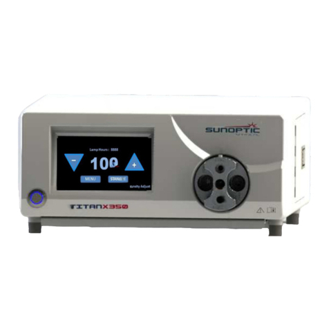
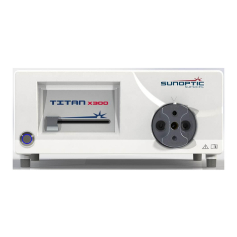
Sunoptic Surgical Titan X400 User manual

LIT-259 Sunoptic Surgical®
Rev. B English)
Page 1 of 100
Titan X400
(US Patent 9,772,094 and 7,510,313)
Xenon Illuminator with Manual Dimming
Control Operator Manual
Sunoptic Technologies®
6018 Bowdendale Avenue
Jacksonville, FL 32216 USA
Customer Service: 904 737 7611
Toll Free 877 677 2832
AJW Technology Consulting GmbH
Breite Straße 3
40213 Düsseldorf, Germany
Telephone: +49 211 54059 6030

LIT-259 Sunoptic Surgical®
Rev. B English)
Page 2 of 100
TABLE OF CONTENTS
1. INTRODUCTION
1.1 Indications for Use
1.2 Functions of Design
2. WARNINGS AND CAUTIONS
2.1 Warnings
2.2 Cautions
3. SPECIFICATIONS
4. CLASSIFICATION
5. OVERVIEW
6. SETUP AND OPERATION
6.1 Device Setup
6.2 Operation
7. CLEANING AND DISINFECTION
8. MAINTENANCE, SERVICING, REPAIR & WARRANTY
8.1 Lamp Replacement
8.2 Limited Warranty
8.3 Repair
8.4 Troubleshooting
9. END OF PRODUCT LIFE
10. SYMBOLOGY

LIT-259 Sunoptic Surgical®
Rev. B English)
Page 3 of 100
1. INTRODUCTION
Congratulations on the purchase of your new Titan X400 Xenon Illuminator!
This user-friendly Xenon Illuminator is a high efficiency light source utilizing state-of-the-art illumination
technology. It offers a variety of features such as:
• 5600 K daylight brightness for perfect color definition
• Quiet operation
• Compact and light weight
• Turret which adapts to various types of light guides
• Mechanical Iris
• Easy lamp replacement
• Lamp life display indication
In short, you have chosen the best and we would like to make sure you receive the optimal results with
your new illuminator by using it correctly.
This Operator Manual will help you to install the device and optimally integrate it with other components
of your system. It will also instruct you how to operate the illuminator and how to keep it clean. It will
give you maintenance and service guidelines as well as recommendations for best performance
results.
1.1 Indications for Use
The intended use of this device is to provide light for fiberoptic cables and instruments – providing
light for instrumentation via fiberoptic cables for use in surgical fields.
The xenon illuminator is intended to be used in a controlled operating room environment by
qualified medical personnel. The illuminator is provided non-sterile and is not intended to be
sterilized. The system has an expected, but not limited, three-year service life.
The illuminator is not intended to be used for monitoring, diagnostic, or other life support functions.
This device does not sustain nor support life. The device is not intended to compensate for injury,
handicap, replacement or modification of anatomy, or control of conception. No special intervention
is necessary in the event of device failure. As such, this device has no essential performance as
defined by IEC 60601-1, and should this device fail to operate, a suitable backup should be
available for any procedure where it may be used.
There are no contraindications.
1.2 Functions of Design
The xenon illuminator comprises a standalone, mains-powered illuminator that produces 390klux
(minimum) with a standard headlight at 16-inch (40cm) distance in the visible spectrum range. The
illuminator is typically used with a fiberoptic light guide that connects to a light port located on the
front panel. Light intensity is controlled via dimming knob located on the front panel of the console.

LIT-259 Sunoptic Surgical®
Rev. B English)
Page 4 of 100
2. WARNINGS AND CAUTIONS
Use of this equipment may present hazards to the user and/or patient. Before operating this device,
please read this operating manual thoroughly and follow all warnings, cautions, and instructions for
use. The words warning, caution, and note carry special meaning and should be carefully reviewed:
WARNING: Indicates risks to the safety of the patient or user. Failure to follow warnings may result in
injury to the patient or user.
CAUTION: Indicates risks of improper use and/or damage to the equipment. Failure to follow cautions
may result in loss of function or product damage.
NOTE: Indicates special information to clarify instructions or present additional useful information.
The appropriate “WARNING”, “CAUTION” or “NOTE” symbol in this manual is intended to alert the user
to the presence of important operating and maintenance instructions in the manual.
2.1 Warnings
• Federal law restricts this device to sale by or on the on the order of a licensed practitioner.
• The illuminator produces highly concentrated light. Avoid shining light beam into eyes or
looking directly into the light beams at the ends of connected instruments and/or light
guides. When not using the device, it is advised to fully dim the illuminator.
• Qualified personnel must determine a safe working distance between the ends of
connected instruments and/or light guides and the patient for each application. There is a
risk of patient injury if a light guide or instrument connected to the light source comes to
close to the patient.
• User is responsible for determining if interruption of light output will create an unacceptable
risk. Having a backup illuminator is advised.
• Not suitable for use in presence of flammable anesthetic mixture with air or with oxygen
or nitrous oxide.
• For endoscopic procedures: the illuminator should only be used with type BF endoscopic
instruments which have been certified to IEC 60601-1 and IEC 60101-2-18.
This symbol indicates type BF equipment.
• All devices and/or instruments connecting to the illuminator must be classified as medical
equipment. It is the user’s responsibility to ensure that all equipment used with this device
meets all applicable standards such as IEC 60601-1.
• To prevent fire and/or electric shock, do not open or expose the illuminator to liquids.
• The illuminator-side light guide connection may become hot during use. Allow adequate
time to for end tip to cool before removal from illuminator.
• Instruments and/or light guides connected to the illuminator must be NON-CONDUCTIVE.
There should be no conductive shielding or any conductive connection between the
illuminator and the patient. Such connections present a risk to patient safety.
• Instruments and/or light guides should be clean and dry before being connected to the
illuminator.
• DO NOT modify the equipment without authorization from the manufacturer.
• The illuminator is provided non-sterile and is not intended to be sterilized.
• Use only the power cord supplied with illuminator or medically approved power cords with
less than 200mΩ of ground impedance and less than 16ft (<5m) of length. If unauthorized

LIT-259 Sunoptic Surgical®
Rev. B English)
Page 5 of 100
cables are used, the device may have increased electromagnetic emissions and/or
decreased electromagnetic immunity which may result in improper operation.
• This device meets CISPR 11 Class A limits and is suitable for use in a hospital and
industrial environments. If it is used in a residential environment (for which CISPR 11 class
B is normally required) this equipment might not offer adequate protection to radio-
frequency communication services. The user might need to take mitigation measures,
such as relocating or re-orienting the equipment.
• Performance of this device may be affected in proximity of another device and/or
equipment capable of producing high levels of RF emissions. The device should be used
no closer than 12 inches (30 cm) to any part of RF equipment including cables. In the
event performance of this device is affected due to high levels of RF emissions, relocation
of the suspected device and/or equipment producing high levels of RF emissions, or the
headlight system may reduce or eliminate the problem.
2.2 Cautions
• Before each procedure, carefully check the illuminator for damage. DO NOT use a
damaged illuminator.
• The user should verify the light guide end tip and the active illumination port are of the
same type before insertion. DO NOT attempt to force an end tip into an incorrect port.
• All servicing and repair must be performed by the manufacturer or qualified service
technicians.
• Ensure that the air vents located on the illuminator are not obstructed to allow the device
to receive the necessary cooling to prevent an overheating.
• Any serious incident that has occurred in relation to the device should be reported to the
manufacturer and the competent authority of the Member State in which the user and/or
patient is established.

LIT-259 Sunoptic Surgical®
Rev. B English)
Page 6 of 100
3. SPECIFICATIONS
PARAMETER
VALUE
Light Source Type
Ceramic 400W Xenon
Color Temperature
5600 K (typ.)
Lamp Life
1000 hours (typ.)
Lamp Replacement
Cartridge replacement
Brightness Control
Mechanical iris control
Light guide adaptor
Rotating turret with STORZ, ACMI, WOLF, and OLYMPUS
Input Power
100-240 VAC, 50/60 Hz
750W (max.)
Circuit Protection
Resettable
Operating Conditions
68 to 104⁰F (20 to 40⁰C), 30 to 85% RH non-condensing, 700 to
1060 hPa
Storage Conditions
-4 to 140⁰F (-20 to 60⁰C), 0 to 95% RH non-condensing, 700 to
1060 hPa
Dimensions
13.3” x 6.1” x 18” (W x H x D)
33.8 x 15.5 x 45.7 cm (W x H x D)
Weight
22 lbs / 10.0 kg
4. CLASSIFICATION
PARAMETER
VALUE
System Classification
FDA Class I, 510(k) exempt
EU Class I, Active device per Annex IX, rule 1
Isolation
Type BF
EMC Certifications
CISPR 11 Class A, IEC 60601-1-2 4th Edition
Electrostatic discharge: ±8 kV contact, ±15 kV air
Radiated RF EM Fields: 3 V/m, 80 – 2700 MHz
EFT / Burst: ±2 kV, ±1 kV signal lines, 100 kHz
SURGE: ±0.5, ±1 kV
Conducted disturbance: 3 V 150 kHz – 80 MHz and 6 V in ISM
bands
Power frequency magnetic fields: 30 A/m
Voltage dips: 0% Un / 0.5 cycles at 0°, 45°, 90°, 135°, 180°,
225°, 270°, 315°, 40 % Un / 5 cycles, 70 % Un / 25 cycles
Voltage interruptions: 0% for 5000 ms
Proximity fields: in accordance with EN 60601-1-2: 2015 table 9
CE Marking
Regulation (EU) 2017/745
Degree of protection against
harmful ingress of water
IPX-0; no protection.
Degree of safety in the
presence of Flammable
Anesthetics
Equipment is NOT suitable for use in the presence of
flammable anesthetics.
Mode of operation
Continuous

LIT-259 Sunoptic Surgical®
Rev. B English)
Page 7 of 100
5. OVERVIEW
FRONT PANEL
No.
Name
Function
1
Lamp Switch
Turns illuminator ON and OFF. Illuminates blue when ON.
2
Intensity Control
Mechanically adjusts light intensity
3
Turret
Auto Shutter turret accepts end tip of fiber optic cable. Light is
shuttered when no cable is present

LIT-259 Sunoptic Surgical®
Rev. B English)
Page 8 of 100
REAR PANEL
No.
Name
Function
1
Fan
Cooling fan
2
Product Label
Device and Manufacturer information
3
Hour Meter
Allows tracking of total running time on unit and provides
tracking of individual lamp running hours
4
Ground Stud
For potential equalization
5
AC Mains Inlet and
Switch
Accepts AC Power cord and switches on AC power
6
Circuit Breaker
Over current protection

LIT-259 Sunoptic Surgical®
Rev. B English)
Page 9 of 100
6. SETUP AND OPERATION
6.1 Device Setup
Place the Illuminator on a stable surface such as a cart, counter, stand, etc.
WARNING: DO NOT use the device in any environment with explosive or flammable gases.
WARNING: Avoid placing the device in an area where the illuminator may be splashed with liquids. A
clear space minimum of 5 inches (12.7 cm) behind and above the cabinet is required. The illuminator
should not be placed where its exhaust will influence other devices, nor where exhaust from other
devices will influence the illuminator.
WARNING: DO NOT obstruct the exhaust or cooling vents of the illuminator. User must ensure that
environment air temperatures surrounding the unit are within the allowable limits.
Make sure the power switch is in the OFF position.
Connect AC power cord to the appliance inlet located on the rear panel of the light source.
CAUTION: Use only power cords provided with the unit or cables approved for medical use.
WARNING: To prevent electric shock, connect power cords of peripheral equipment through medical
isolation transformers.
NOTE: When using a medical isolation transformer, ensure that the transformer has sufficient power
ratings. Ensure that the power cord is connected to mains power with a three-prong plug.
Connect a fiberoptic light guide to the topmost position of the rotating turret, ensuring that the
fiberoptic end tip type matches the accepting port.
6.2 Operation
After the power cable and light guide are properly connected, ensure the illuminator is in the lowest
dimming position, and turn on the illuminator by pressing the mains power switch located on the
front panel. The power indicator light within the switch should illuminate.
Ensuring that the light output from the attached light guide is directed to a safe area, adjust the
intensity control slider until the desired brightness is achieved.
NOTE: The brightness control slider operates a progressive mechanical shutter. The lamp is running
at full power irregardless of the intensity.
The hour meter located on the rear of the unit shows the total elapsed running time of the unit.
When the lamp is replaced, reset the hour meter to track total lamp usage hours on the replacement
lamp.

LIT-259 Sunoptic Surgical®
Rev. B English)
Page 10 of 100
7. CLEANING AND DISINFECTION
WARNING: Ensure that the illuminator is de-energized and disconnected from mains power before
attempting to clean and disinfect.
The illuminator can be wiped down with commercially available cleansers commonly used for
disinfection of electronic equipment in hospitals such as ethyl or isopropyl alcohols, disinfecting sprays
containing quaternary ammonium compounds, or hydrogen peroxide.
WARNING: DO NOT use strongly caustic or acidic cleansers such as “Clorox” hypochlorite bleach,
ammonia, muriatic acid, or similar products. DO NOT use acetone, methyl ethyl ketone, or halogenated
/ chlorinated hydrocarbon solvents or cleansers containing any of these restricted compounds.
Apply cleaning agents by light spray or dampened towels. Do not pour liquids onto the device. Do not
allow liquids to enter the device seams or ventilation openings.
Follow all applicable bloodborne pathogen procedures as required by OSHA and/or your hospital
when cleaning and disinfecting the product.
WARNING: The illuminator is not sterilizable. DO NOT attempt to autoclave the device.
8. MAINTENANCE, SERVICING, REPAIR & WARRANTY
Performance of preventative maintenance is not essential. Defective items or equipment are to be
serviced and repaired exclusively by persons authorized by the manufacturer. All repair work shall
employ original manufacturer’s parts only.
8.1 Lamp Replacement
WARNING: Ensure that the illuminator is unplugged from mains power and de-energized before
attempting to replace the lamp.
WARNING: Ceramic Xenon lamps are at high internal pressure when cold and at operating
temperature. Ceramic Xenon lamps may unexpectedly rupture resulting in discharge of hot fragments
of quartz and/or glass and metal. Only handle lamps with protective covers in place.
WARNING: Do not change lamp while touching patient.
NOTE: This illuminator is designed for exclusive use with the Sunoptic Surgical P/N: SSX0400 lamp
module. Failure to use this lamp could void warranty.
Turn unit off and unplug from mains power. Open lamp door located on side of illuminator.
Move the lamp positioning lever (found to the right of the lamp) clockwise, from horizontal to vertical,
and pull the lamp cartridge out.
Grasp only the horizontal top and bottom grip flanges of the plastic housing of the lamp, pull straight
out to remove the lamp. Insert a new one (lamp pointed to the left), pushing firmly to assure full
engagement to the power connectors. Lower the lamp engagement lever counterclockwise, from
vertical to horizontal, and observe that the lamp rises about 3mm as it moves to its proper operating
position.
Log the serial number and hours on the hour meter. Close the lamp compartment door. Re-connect
the power cord and turn the light source on according to 6.1. Reset hour meter to zero by
depressing hour meter reset button on rear panel.

LIT-259 Sunoptic Surgical®
Rev. B English)
Page 11 of 100
8.2 Warranty
The illuminator carries a 3-year warranty from the date of shipment on workmanship and all defects
of material.
Should your product prove to have such defects within three years of shipment, Sunoptic
Technologies® will repair or replace the product or component part without charge. Should your
product(s) need servicing under this warranty, please contact Sunoptic Technologies® or a local
distributor for return authorization documentation.
Please carefully pack the unit in a sturdy carton and ship it to the factory. Please include a note
describing the defects, your name, telephone number and a return address. Warranty does not
cover equipment subject to misuse, accidental damage, normal wear, and tear or if transferred to
a new owner without authorization from Sunoptic Technologies®. This warranty gives you specific
legal rights and you may also have other rights that vary from state to state.
8.3 Repair
You may return your product(s) for repair, shipping prepaid to the factory. Your product will be
inspected, and an estimate of repair charges will be submitted to you for approval.
PHONE: +1 (877) 677-2832 INTERNATIONAL: +1 (904) 737-7611
FAX: +1 (904) 733-4832
8.4 Troubleshooting
Problem
Solutions
The power indicator (refer to
section 5) is not lit.
Check that the AC power cord is properly connected
Check the circuit breakers. If necessary, reset.
Power input switch is in the off position
The power indicator is lit but the
lamp will not ignite.
Check lamp connection.
Check that the lamp door cover is secured.
Check hourmeter if lamp hours exceed the rated lamp life
Replace the lamp (refer to 8.1).
9. END OF PRODUCT LIFE
In accordance with the European Waste from Electrical and Electronic Equipment (WEEE) directive,
we encourage our customers to recycle this product whenever possible. Disposal of this unit must be
performed in accordance with the applicable local environmental regulations.
In the US a list of recyclers in your area can be found at: http:/www.eiae.org/.
Please contact customer service to issue a return authorization to return product to manufacturer at the
end of product life.
10. SYMBOLOGY
Manufacturer
Date of manufacture (YYYY-MM-DD)
Symbol for Authorized Representative in the European Community

LIT-259 Sunoptic Surgical®
Rev. B English)
Page 12 of 100
Caution, consult accompanying documents
Consult Instructions for Use
CE mark
Do not use if package is damaged.
Not for disposal in general waste
Medical device
Caution: Hot Surface
Caution: Dangerous Voltage
Storage / Shipping Humidity
Barometric Pressure
Unique Device Identifier
Keep Dry
AC Current
Product Safety Mark
Equipotentiality
Power on
Power off
Type BF
Protective Earth (Ground)
Table of contents
Other Sunoptic Surgical Medical Equipment manuals
Popular Medical Equipment manuals by other brands

Leica
Leica FL560 user manual

Rehan Electronics
Rehan Electronics i-Pulz 2 user manual

Verity Medical
Verity Medical NeuroTrac Sports Operator's manual

Akron
Akron 8601B operating manual

Scaleo medical
Scaleo medical Poweo CITY user manual

Atos Medical
Atos Medical Provox HME System Cassette Patient's and Physician's Manual

Joerns
Joerns Oxford Stature quick start guide

Interacoustics
Interacoustics VRA Screen Instructions for use

Armstrong Medical
Armstrong Medical AquaVENT FD140 Instructions for use

Dräger
Dräger Babytherm 8004 Supplement

Westmed
Westmed Circulaire II Hybrid Instructions for use

Fresenius Medical Care
Fresenius Medical Care 2008K2 manual