5OMNI2 Rev.A
ENGLISH
WARNING!
Programming and diagnoscs should only be conducted by
health care professionals with in-depth knowledge of R-net
electronic control systems. Incorrect programming could
result in an unsafe setup of a vehicle for a user. Sunrise
Medical accept no liability for any losses of any kind if the
programming of the control system is altered from the
factory preset values.
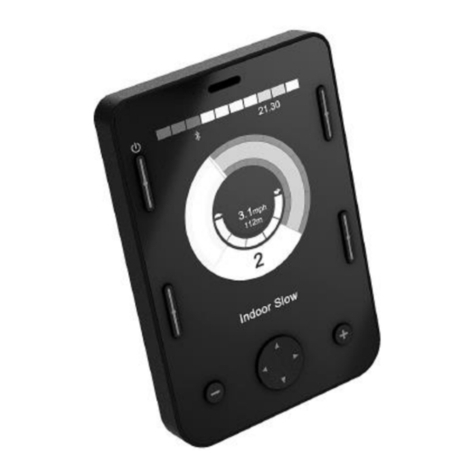
LCD Screen, (Fig. 1.0).
A full color, backlit LCD screen that can show OMNI2
conguraon details and operang informaon. More details
of actual displays are given in the LCD Screen Details Secon
and throughout this manual.
On/Off Button, (Fig. 1.0).
The On/O buon provides a complete power-down of the
control system electronics. In addion to the buon mounted
on the Display Secon, there is facility for an oponal,
externally-mounted switch on the Input Secon, which can
be operated by the user, see Secon External On/O Switch
Input.
Profile Button, (Fig. 1.0).
The Prole buon allows you to change between the available
Drive Proles.
Settings Button, (Fig. 1.0).
The Sengs buon launches the Sengs Menu screen.
Mode Button, (Fig. 1.0).
The Mode buon allows you to change between the available
Modes.
Navigation Buttons, (Fig. 1.0).
The array of 4 Navigaon buons allows the funcon screens
to be navigated.
- / + Buttons, (Fig. 1.0).
These buons make adjustments to speed and highlighted
parameters.
Display/Input Section Connectors, (Fig. 1.0 & 1.1).
These connectors are used to link the two OMNI2 Secons
together.
Use only the authorised Sunrise cable.
Communications Connector, (Fig. 1.1).
This connector is used to link the OMNI2 to the R-net system.
Charger Socket, (Fig. 1.1).
This 3-pin socket can be used to charge the wheelchair
baeries and, dependent on system programming, to lock the
wheelchair. For details of baery charging, refer to Chapter 9.0
& to the wheelchair Owner’s Manual or User Instrucons.
USB Charging Port, (Fig. 1.1).
This ‘Type A’ USB socket can be used to charge devices such as
mobile phones.
9-Way D-Type Specialty Input Device (SID) Connectors,
(Fig. 1.1).
These provide connecons to analogue or digital SIDs. There
is a facility to detect if a mang connector is in place; and
provision of a low current 12V supply.
User Switch Jacks, (Fig. 1.1).
There are two stereo 3.5mm / 1/8” jack sockets which provide
connecon to the User Switches. Full details of User Switches
can be found in the Connecon of SIDs secon.
There is also facility to detect if the mang User Switch jack
plug is in place.
External On/Off Switch Jack, (Fig. 1.1).
This is a stereo 3.5mm / 1/8” jack socket which provides
connecon to a user operated On/O buon. This connecon
is oponal and the OMNI2 will funcon normally without it.
Sip and Puff Input, (Fig. 1.1).
This input will accept a 3.5mm / 1/8” pipe connected to a Sip
and Pu mouthpiece.
Assignable Buttons
Via programming, it is possible to change the funcon of most
of the buons . This includes assigning the funcon of another
buon or making the buon act as a shortcut to a parcular
acon, such as moving a seang funcon. Addionally, a
buon can be assigned a second funcon, which is accessed
by depressing the buon for a length of me.
For more informaon on changing the funcon of a buon
and assigning a second funcon, please contact your servicing
agent.


