Super Anchor Safety Version 07 SCN User manual

Version 07
SCN
Instruction Manual / Product Guide
©
English Pages 1-24 Spanish Pages 24-47

ORIENTATION / INSTRUCTION / SPECIFICATION MANUAL
QUICK STRAP™:
Made from 1.75” wide, 5,000 lbs. polyester webbing. The strap is 48”
long and is fitted with a zinc-plated D-ring for attaching the lifeline.
The Quick Strap™wraps around wood or steel framing members.
WARNING TO USER
All persons using this fall protection equipment must read, understand and
receive training from this manual before use. Additional training may be
required by a “competent”* or “qualified”* person in order to identify
potential hazards that could result in serious injury or death. For additional
information regarding anchorage installation or other fall protection equip-
ment, consult Super Anchor Safety’s®web site at www.superanchor.com.
Or contact our sales office in Woodinville, WA USA at 425-488-8868.
*See Definitions, Page 21
ADJUSTABLE
HINGED ANCHOR™:
11 ga. di-chromate plated steel with a stamped D-ring
attachment point for lifeline connection. Installs with
factory certified nails or screws. Do not use on slopes
greater then 20/12. Rated for maximum 5,000 lbs.
This equipment is designed to be used as a complete system for personal fall protection and is rated
for one person at a time. It meets the criteria for all fall arrest equipment specified in OSHA Subpart
M 1926:502 and ANSI Z359.1-1992. All of the components are factory certified for component com-
patibility and may be used with other anchorage devices manufactured by Super Anchor Safety®. All
components are rated for a maximum user weight of no more than 310 lbs.
FULL BODY HARNESS:
The body harness is made from 1.75” polyester webbing and is rated at 5,000 lbs. Leg and chest
straps are adjustable for a personal fit using friction-type buckles. Each harness has a serial number
on the warning label. Shock absorber or accessory lanyards attach to the 5,000 lbs. proof-loaded
D-ring located on the back of the harness.
SHOCK ABSORBER:
Fabricated from 1.75” polyester tear-away webbing. It has a maximum elongation of 42” and is
encapsulated in clear shrink tubing. The harness attachment end is fitted with a double locking
snaphook. The shock absorber is permanently attached to the rope grab witfh a sewn loop. When
used as specified in this manual, the shock absorber should limit the MAF (maximum arrest force)
to no more than 900 lbs. for a worker with a maximum weight of 310 lbs. (including tools) when
subjected to a 6 ft. free fall. The minimum force needed to initiate absorber deployment is between
650 lbs. and 750 lbs.
ROPE GRAB:
The mechanical, single-direction rope grab is rated for 5,000 lbs. of force and is factory attached to
the shock absorber. It has a corrosion resistant finish. The rope grab is adjusted on the lifeline by
holding the cam locking-lever in the open position. During normal operation the rope grab will remain
at its fixed position on the lifeline and will lock when subjected to the tension of a sudden force or
free fall. Note: The rope grab only locks when correctly installed onto lifeline.
LIFELINE:
Made from 5/8”, 3-strand, 9,200 lbs. test polyester and spliced with a double-locking snaphook for
attachment to the anchor. The eye splice and product warning label are encased in clear shrink
tubing. A “termination knot”* is tied 12” from the tail-end of the lifeline to prevent the rope grab
from coming off due to “accidental disengagement.”*
FACTORY SUPPLIED
ANCHORAGE DEVICES:
2

TABLE OF CONTENTS
COMPONENT ORIENTATION 2
TABLE OF CONTENTS 3
SYSTEM SET UP & INSPECTIONS
HARNESS ADJUSTMENT AND COMPONENT CONNECTIONS 4
SECTION 1
INSPECTIONS: SHOCK ABSORBER / HARNESS 5
SECTION 2
ADJUSTING LIFELINE / ROPEGRAB TO LIMIT FREE FALL 6
SECTION 3
ANCHOR SERVICE ZONES 7
SECTION 4
INSTALLING / MAINTAINING / INSPECTING ROPE GRAB 8
SECTION 5-A
INSPECTIONS: LIFELINE / SNAPHOOK 9
SECTION 5-B
ANCHOR SYSTEMS
INSTALLING HINGED ANCHOR™10
SECTION 6-A
INSTALLING QUICK-STRAP™ANCHOR 11
SECTION 6-B
PERMANENT ANCHORAGE DEVICES: ARS / RETRO-FIT™12
SECTION 7-A
PERMANENT ANCHORAGE DEVICES: RS-20 ™/ WALL MOUNT™13
SECTION 7-B
TEMPORARY AND REUSABLE ANCHORS: 3-K™/ 5-K™14
SECTION 7-C
MOVABLE ANCHORS: UNIVERSAL™/ ARS / SAFETY BAR™15
SECTION 7-D
COMPONENT COMPATIBILITY
LIFELINES AND ANCHORAGE DEVICES 16
SECTION 8-A
BODY HARNESS AND ROPE GRAB 17
SECTION 8-B
NON-COMPATIBILITY
LIFELINES AND LANYARDS 18
SECTION 8-C
HARNESS / ROPE GRABS / CONNECTORS 19
SECTION 8-D
FALL HAZARDS
LEADING EDGE / SWING FALL / GABLE EDGE 20
SECTION 9
DEFINITIONS
TERMS AND DEFINITIONS 21
SECTION 10
PARTS LIST 22
INSPECTION REPORT FORM 23
USER TRAINING LOG: ENGLISH AND SPANISH 24
SPANISH TRANSLATION 24-47
SPECIFICATIONS OF USE:
All instructions and references to fall protection equipment con-
tained in this manual SPECIFICALLY APPLY to products manufac-
tured / distributed by Super Anchor Safety® and do not apply to
equipment manufactured by other fall protection companies.
COMPONENT
COMPATIBILITY:
When using fall protection equipment manufactured by Super
Anchor Safety®, “component compatibility”* is ensured. This
means that our equipment has been designed, tested, and certified
to work together without creating unforeseen hazards. Any time
equipment from other manufactures is used with our equipment,
“component compatibility”* needs to be ensured by a “qualified
person”* that is in harmony with OSHA, ANSI, or other fall protec-
tion equipment standards that govern their use in the area where
you are working.
NON-SPECIFIED USE:
HORIZONTAL LINES /
MULTIPLE USERS
Unless otherwise stated, the equipment shown in this manual is
specifically rated for a single person only. Any modification of use,
such as for more than one person, or for horizontal line** configu-
rations are required to be engineered by a “qualified person.”*
**OSHA 1926-502(d)(8).
3
*See Definitions, Page 21

ADJUSTING A
NEW HARNESS:
Hold the harness by the metal D-ring. Unbuckle the
chest strap and leg strap friction buckles. Remove any
twists in the webbing. Insert arms through the shoulder
straps so the D-ring is on your back and the arrow indi-
cator on the shoulder strap, shown in Fig. 3, is
pointing up toward your head. Leg straps should be
hanging down with no twists or tangles. Adjusting for
personal fit may require the harness to be put on and
taken off several times.
CHEST AND SHOULDER
STRAP ADJUSTMENT:
1. Align the shoulder straps so they are parallel to
each other as shown in Fig. 1. Buckle the chest strap
by inserting buckle "A" through buckle "B" as shown in
Figs. 5, 6 and 7below. Adjust the chest strap length by
moving the webbing through buckle "A" so the shoulder
straps do no extend past your armpits. For an average
size person the length between the shoulder straps
should be no more than 12". The chest strap should be
positioned at armpit level as shown in Fig. 1.
SECTION 1
HARNESS ADJUSTMENT AND COMPONENT CONNECTIONS
D-RING ADJUSTMENT:
3. The D-ring on harness back should position about the center of
the shoulder blades as shown in Fig. 2. Position the D-ring pad at
least 4" below the top of your shoulders but no more than 6". Adjust
the D-ring location by moving the webbing through the slots in the
D-ring pad (Fig. 3) and taking up excess webbing through the leg
strap friction buckles (Fig. 1). The chest strap position may have to be
adjusted after moving the D-ring pad.
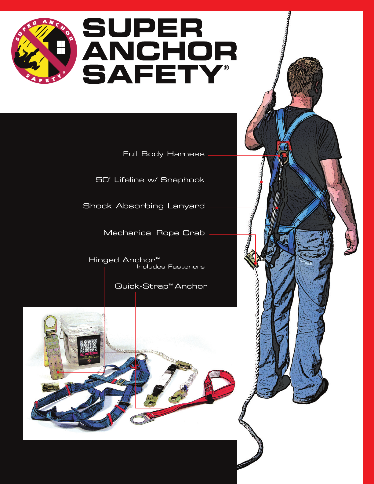
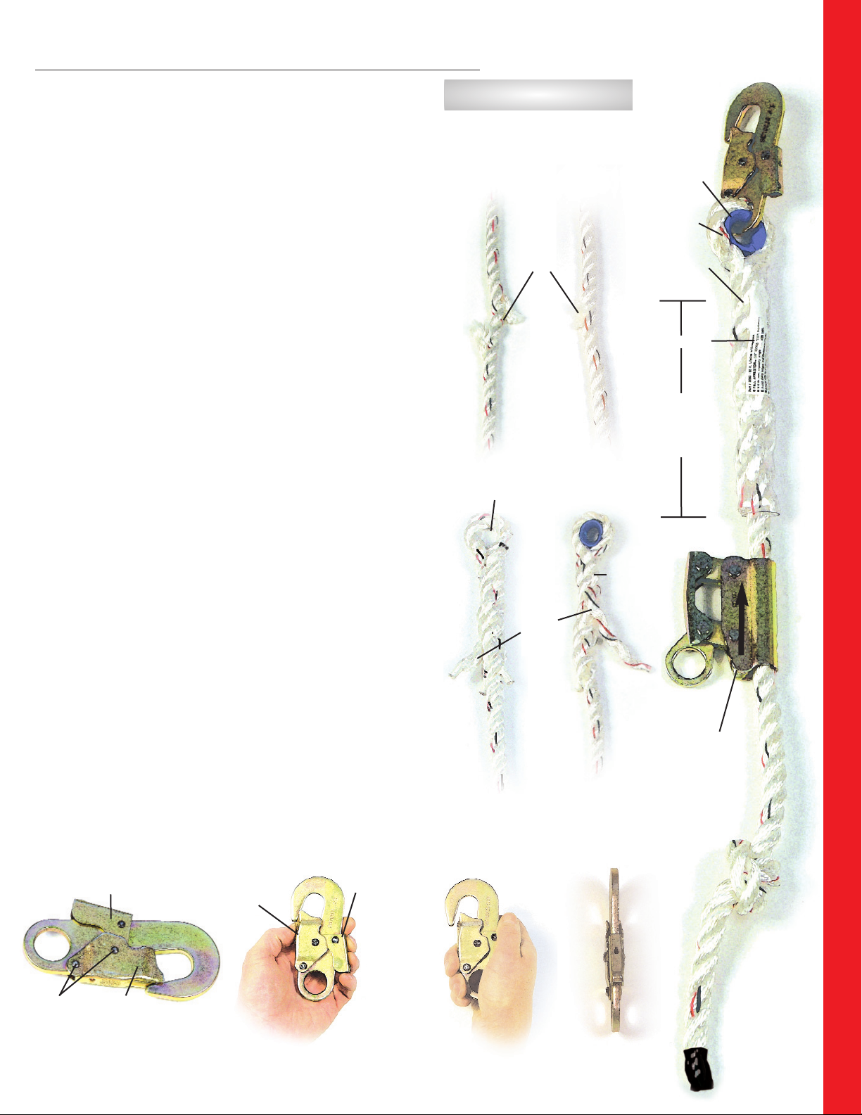
4. Connect shock absorber as shown in Fig. 3 to the back of the
D-ring on the harness with the snaphook. Make sure the snaphook
functions properly by following instructions in Section 5-B.
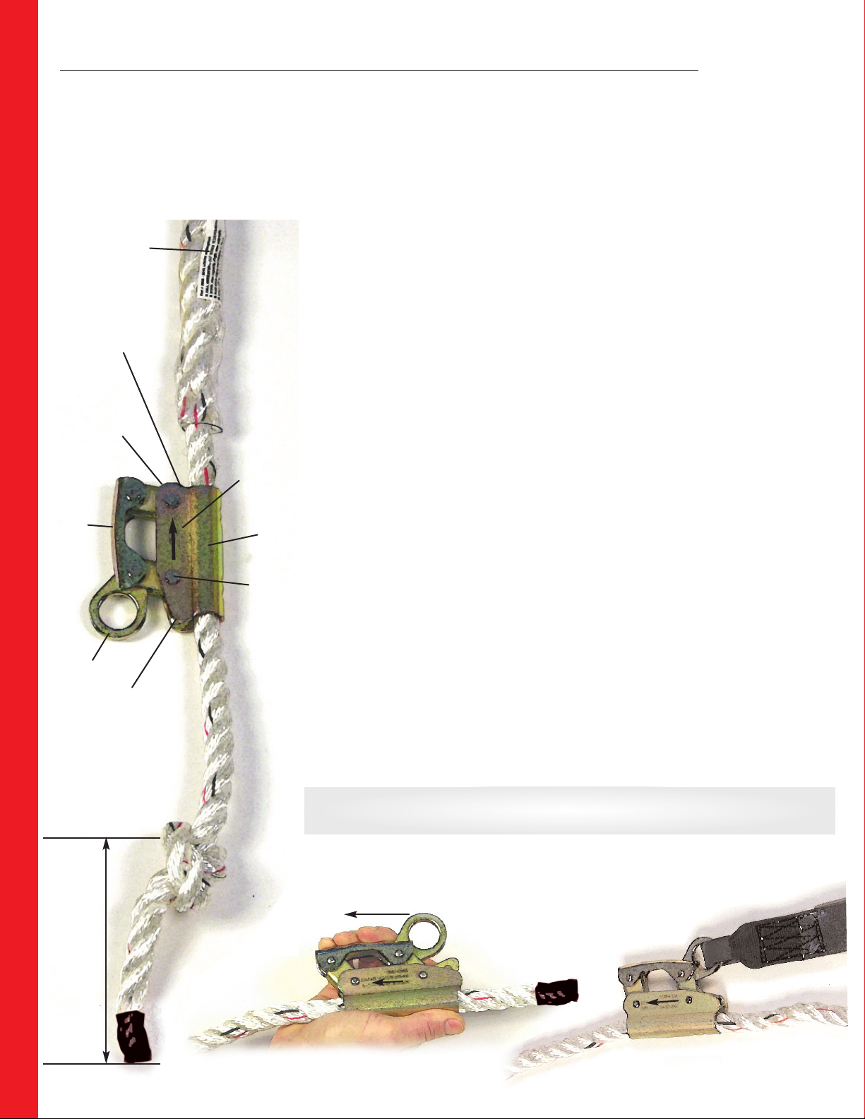
5. Lifeline should be installed through the rope grab with the arrow
indicator pointing toward the anchor-point end of the lifeline shown in
Fig. 4. Follow the instructions for the rope grab adjustment in
Section 3 before use.
FRICTION BUCKLES:
7. Friction buckles are locked by inserting the smaller "A" buckle
through the larger "B" buckle (Fig. 5). Turn "A" buckle at an angle as
shown in Fig. 6 and slide through "B" buckle. The "A" buckle should
lay flat over the top of the "B" buckle as shown in Fig. 7.
LEG STRAP
ADJUSTMENT:
2. Buckle the leg straps and adjust for a snug
fit. Shorten or lengthen the strap by unbuck-
ling and moving the webbing through the "A"
buckle. Store excess webbing using keepers
shown in Fig. 7.
WEBBING KEEPERS:
8. Excess webbing from the chest and leg/shoulder straps are stored using the
plastic webbing keepers shown in Fig. 7. Webbing strap ends are terminated by
folding over and sewing in place. This prevents the webbing from sliding back
through the "A" buckle. For this reason, do not cut off excess webbing. If
termination overlap is missing do not use the harness.
WARNING:
IF THE HARNESS IS NOT ADJUSTED
FOR A SNUG FIT, IT IS POSSIBLE TO
COME OUT OF THE HARNESS IF YOU
FALL. THE CHEST STRAP MUST BE
CLOSED AND BUCKLED AT ALL
TIMES WHEN YOU ARE USING
THE HARNESS FOR FALL
PROTECTION.
Fig. 5 Fig. 6 Fig. 7
“A” “B”
Insert small buckle "A"
into large buckle "B" at an angle Buckle "A" lays over
the top of buckle "B"
Webbing
Keepers
"A" on top
Fig. 3
approx 12"
Adjust webbing
through D-ring
pad slots
D-ring pad
D-ring
Shoulder
strap arrow
Shock absorber
Fig. 1
Max length
below shoulder
6"
Harness
D-ring at
center of
back
Rope grab
Make sure "arrow" on
rope grab is pointed
toward anchorage point
6. Attach lifeline to anchorage device
with the snaphook. Ensure the snaphook
is locked and the lifeline is not twisted
or entangled.
Shoulder strap
Chest strap
position
(armpit height)
Leg strap
Friction buckles
NOTE: Shoulder strap webbing is adjusted by shortening
or lengthening the leg straps.
Fig. 4
Webbing overlap
Fig. 2
4

The shock absorber is designed to arrest a fall one time only and it must be
replaced. The original length is approximately 17". When the absorber is subject-
ed to a free fall the tear-away fabric will rip out a maximum of 42" as it slows
the fall and then comes to a complete stop. It takes about 650-750 lbs of force
to deploy or initiate the rip out function.
1. SHOCK ABSORBER:
The absorber snaphook and rope grab are factory attached with a web loop as
shown in Fig. 1.
REMOVE FROM SERVICE IF ANY OF THE FOLLOWING INSPECTIONS FAIL:
a) Snaphook or rope grab are missing.
b) Snaphook does not pass inspection in Section 5-A.
c) Web loop at snaphook or rope grab are worn or cut.
d) Clear shrink tube cover is missing, cut, or damaged. Fig. 2-B
e) Warning label is missing.
f) The absorber has been fully or partially deployed in a fall or by applying
some other force as shown in Fig. 2-A. and is longer than the factory
length of 17".
g) Webbing stitching is missing, cut, or loose.
2. BODY HARNESS:
REMOVE FROM SERVICE IF ANY OF THE FOLLOWING INSPECTIONS FAIL:
a) Webbing is cut or damaged in any way.
b) Webbing stitches are loose, pulled apart, broken or cut. Fig. 6
Inspect webbing overlaps and stitches on the underside of stitch pattern
as shown in Fig. 7.
c) Friction buckles are bent, cut, damaged or corroded. Small buckle "A"
inserts through buckle "B" and locks in place. Fig. 8
d) Chest strap webbing holders (black plastic) are broken or missing. Fig. 5
e) D-ring chafe pad slots where webbing passes through are broken. Inspect
back side of pad. Fig. 4
f) Front side of chafe pad D-ring is missing, broken, cracked or corroded.
Fig. 3
g) Plastic webbing keepers and webbing terminations are loose, broken or
missing. Fig. 8
h) Harness arrow and/or warning label are missing. Fig. 3, 9
SECTION 2
INSPECTIONS: SHOCK ABSORBER / HARNESS
Shock Absorber has
been deployed
(ripped out)
Plastic
Shrink
Tube is
missing
Plastic
shrink
tube
and
warning
label
Web loop
not worn
or cut
Rope
grab
attached
Snaphook
Attached
Fig. 2
“A” “B”
Fig. 1
D-ring
pad
(front
side)
D-ring
intact
Direction
arrow label
D-ring
pad
(back
side)
Slots not
broken or
missing
Fig. 3 Fig. 4
Shoulder straps
Chest strap
Chest strap
webbing
holders
Fig. 5
Slots not
broken or
missing
Fig. 6 Fig. 7
Stitch pattern on front and back
have no cut or broken stitches.
Underside of webbing overlap have
no cut or broken stitching.
Web termination
sewn and not
loose or missing
Buckle
"A" fits
through
buckle
"B" and
lays flat. Warning label
serial #
Webbing
keepers
Fig. 8
Fig. 9
Length is
approx.
17"
Web loop
not worn
or cut
Back
Side
Tear
Away
Fabric
Front Side
ABSORBER
FABRIC
The absorber cover fabric is
black polyester. The tearaway
webbing is white polyester
5

OSHA 1926:502(d)(16)(iii) Allows a worker to free fall no more than 6 ft. before
his equipment begins to arrest the fall. During a fall the rope grab device locks
onto the lifeline when all the slack of the various components are taken up in
the fall. The shock absorber will deploy, slow the fall, and the worker will come
to a complete stop before contacting the ground or a lower level.
The 6 ft. length is measured from the “leading edge”* (as shown in Fig. 1,
where the worker is standing) to the point where the fall begins to arrest
(Fig. 1 foot position to Fig. 2 foot position).
SECTION 3
ADJUSTING LIFELINE / ROPE GRAB TO LIMIT FREE FALL
ADJUSTING ROPE GRAB FOR FREE
FALL LENGTH:
1. Position your rope grab a few feet below the snaphook on your lifeline with the rope
grab arrow pointing toward the anchor-point end of the lifeline as shown in
Section 1,
Figs. 3 & 4
, and connect your lifeline to a properly installed anchor point.
2. Position the shock absorber/rope grab under your arm as shown in Fig. 1 above,
and descend in a straight line toward the leading edge while holding the rope grab
locking lever in the open position shown in
Section 5A, Fig. 2
. Slide the rope grab
down the lifeline keeping all the slack out of the line.
3. With your feet at the “leading edge”* position, release the rope grab locking-
lever. The shock absorber and rope grab should be in tension as shown in Fig. 1.
Mark the position of the rope grab on the lifeline. At this position your free fall should
be no more than the length of the D-ring to the leading edge: 52” as shown in Fig. 1,
(B) of our example.
4. Slide rope grab down the lifeline 20”, as shown (C) in our example. The adjustment
slack added to the lifeline length will allow you to move in a radius to the left or right
of the anchor center point while limiting your free fall to 6 ft. As you continue to
advance along the leading edge, the adjustment slack will reach its maximum length at
the “anchor service-zone”* overlap, which is the intersection along the leading edge
shown in
Section 4, Fig. 3
. The lifeline will be in tension. In order to continue working
along the leading edge, the worker will have to connect to a different anchor point.
LENGTH OF FALL:
The approximate length of a fall shown in Fig. 3 includes the following: Free-fall
72”(A), absorber deployment 42”(D) and harness stretch 12”(E). Note: rope grab
deceleration is less than 2”.
Approximate length of fall from leading edge to full arrest is 11 ft. (F).
NOTE: The “length of fall” may vary depending on the harness D-ring height of the
individual worker and how well the harness is adjusted for snug fit. Calculate your own
personal fall protection plan to avoid contacting a lower level or the ground if you fall.
*See Definitions, Page 21
The following method to gauge a free fall is a recommen-
dation only and all measurements in this manual are
EXAMPLES ONLY. Each worker will need his own personal
fall protection plan.
MEASURE THE
D-RING LENGTH:
From a standing position, measure the length from your
own D-ring to your feet. Deduct this length from 72”. This
is the amount of “adjustment slack” for your own personal
fall protection plan.
ADJUSTMENT
SLACK EXAMPLE:
The length from the harness
D-ring to the leading edge is
52”(B). To find the amount of
adjustment slack, deduct 52”
from 72”.
The “adjustment slack” in the
lifeline is 20”(C)
Fig. 1
Rope grab
tension
position
Harness D-ring
Move rope grab
20" down line for
adjustment slack
Fig. 2
Foot position
Full arrest
position
Fig. 3
Approx. Free Fall Length
20ft rafter length
(B)
D-ring
Height
52”
(C)
Adjustment
slack
20"
Leading edge
(D)
Absorber
deployment
42"
(F)
11 FT.
(E)
12"
Harness
stretch
Ground, lower level, or hazard below
6
(A)
72" Free
Fall
length
Lifeline
in tension
20”
Leading Edge Line
Limiter Knot
Position (Optional)

Fig. 2 Fig. 3 Fig. 4
Anchor
Point
"B"
Lifeline
Position
"B"
Rope
grab
Maximum limit
of travel at zone
"A" leading
edge.
Service Zone
overlap area
20" adjustment slack
Lifeline
"A"
Service Zone "A" Radius
Anchor
Point
"A"
Limiter
Knot
Leading Edge
Service Zone "B" Radius
7
SERVICE ZONE:
The “anchor service zone”* is the area of fall protection provided by a single anchor point.
A lifeline attached to an anchor point becomes a radius line that creates a 360º circle over
the work area as shown in Fig. 1. When a portion of the circle extends beyond the leading
edge, as shown by the blue shaded area at the bottom of Fig. 1, the worker is exposed to
a free fall. In order to limit the free fall to no more than 6 ft., the worker needs to adjust his
position on the lifeline by using the rope grab as shown in
Section 3, Fig. 1
.
ANCHOR LOCATION:
Some anchors can be installed as permanent fixtures, while others serve as temporary
anchor points that are removed after use. “Anchor service zones” provide a way to calcu-
late how many anchors may be needed and where to locate them.
USING SERVICE ZONES TO LIMIT
FREE FALL:
A single anchor point, shown in Fig. 1, provides fall protection for the entire area within the
radius of anchor “A”, while limiting free fall to 6 ft. along the leading edge fall hazard. The
area outside the “A” “service zone” will require using another anchorage point.
EXAMPLE:
Lifeline “A” rope grab position is adjusted 20” from the leading edge so as to limit the free
fall to 6 ft. as shown in Fig. 4. The worker may travel to any area on the work surface that
is inside service zone “A” as long as there is no other exposure to a fall hazard. When
working along the leading edge where zone “A” overlaps into zone “B” shown in Fig. 3, the
worker can not travel into zone “B”Leading Edge because the rope grab position on the
lifeline has reached its limit. In order to do work in zone “B” along the leading edge, the
worker will have to disconnect from anchor point “A” and connect to anchor point “B” as
shown in Fig. 2. If the worker unlocks the rope grab and continues to move along the
leading edge, the free fall will be greater than 6 ft.
SECTION 4
ANCHOR SERVICE ZONES
WARNING:
FALL HAZARD:
Note: If the rope grab is adjusted
on lifeline “A” to allow travel into
zone ”B”, the free fall and swing
fall hazard will become greater
than 6 ft. Refer to
Section 9
for
common fall hazards.
NOTE: A Jobsite Safety Plan (JSP)
or personal fall protection plan
may allow for limited duration
exposure to free falls.
As the worker in Fig. 4 travels
along the leading edge toward
Fig. 3, the rope grabs fixed
postion on the lifeline will force
him up-slope away from the
leading edge where the zone
overlaps occur.
SAFETY
STATISTIC
Falls from elevated work sur-
faces are among the top 3
leading causes of death on
construction sites in the US.
*See Definitions, Page 21
Service Zone
"A"
Ridge
Slope
Anchor Point
"A"
Free Fall Hazard
Fig. 1
Radius
These areas not
protected by
zone "A"
Leading edge
Limiter Knot:
The rope grab position on the lifeline is used as a reference point
for the free-fall based on the adjustment slack. However, during
the course of work, the rope grab position can change. To mark
or gage the adjustment slack position shown in
Section 3, Fig. 1,
a limiter-knot may be tied just below the rope grab as a gauge to
mark the maximum free fall length.

8
SECTION 5-A
INSTALLING / MAINTAINING / INSPECTING ROPE GRAB
The mechanical rope grab device is pre-installed onto the lifeline at the factory. An arrow indicator is stamped onto the rope chamber of the grab and must always
point to the anchor attachment end of the lifeline in order to function properly. The tail end of the lifeline has a "termination knot"* tied approximately 12" from the
rope end to prevent the rope grab from coming off the end of the lifeline accidentally. Do not use the lifeline system without the termination knot in place.
TEST PROCEDURE FOR LOCKING FUNCTION:
Before each use and anytime the rope grab has been removed from the lifeline, check the locking function:
•With rope grab properly installed, and with the locking cam in the closed position, take the lifeline in one hand and rope grab attachment ring in the other. Pull
lifeline and rope grab in opposite directions. The rope grab should not move on the lifeline. If movement does occur, the rope grab device is defective. Do not use it.
Direction
arrow points to
anchor attach-
ment end of
lifeline
Rope
chamber
Check each
side for a
total of 4
rivet heads
Shock
Absorber
attachment
ring
Locking cam
return spring
inside
Locking
cam
lever
Anchor Attachment
end of lifeline
Termination
knot
12"
from
tail
end
Shrink tube
at tail end
of lifeline
Locking cam open position.
Lifeline slides easily through.
Rope grab should not
move on the lifeline.
Push cam lever
forward to unlock
Fig. 2 Fig. 3
Fig. 1
Cam foot
INSTALLATION / REMOVAL OF THE ROPE GRAB:
NOTE: The mechanical rope grab device can only be removed or installed by sliding it on or off the lifeline
through the rope chamber.
REMOVING THE ROPE GRAB:
•Untie the "termination knot" at the end of the lifeline. Hold the rope grab in the unlock (open cam) position
shown in Fig. 2 and slide it off the lifeline.
INSTALLING THE ROPE GRAB:
•With direction arrow pointed toward the anchor attachment end, hold the rope grab in the open position
shown in Fig. 2 and insert the tail end of the lifeline through rope grab chamber.
•Re-tie the termination knot 12" from the tail end of the lifeline.
CLEANING / MAINTAINING / INSPECTING
THE ROPE GRAB:
Normal use of the lifeline will cause the rope diameter to enlarge as the lifeline absorbs dirt and dust.
Although this will not prevent the rope grab from locking onto the lifeline, it may become difficult to move the
rope grab up and down the lifeline. Check for abrading of the lifeline, cut or damaged filaments, paint, caulk-
ing, or other contaminants on the lifeline which can also interfere with the rope grab movement. Debris can
also get trapped inside the rope grab device and may require cleaning.
CLEANING THE ROPE GRAB:
•Remove the rope grab from the lifeline and clean using air pressure. Move the locking cam up and down
while cleaning. Re-install the rope grab onto the lifeline and check the locking function. DO NOT LUBRICATE
ROPE GRAB OR USE SOLVENTS.
INSPECTING THE ROPE GRAB:
•Remove the rope grab from the lifeline to inspect the interior mechanism of the locking cam.
a) Check for debris in the locking cam.
b) Make sure all locking lever rivets are intact and none are missing or broken.
c) Move the locking lever to the open position shown in Fig. 2. Release the locking lever and it should
return to the closed position shown in Fig. 3. A failure to close may be caused by a broken or damaged
locking cam return spring or some other damage. Check for broken spring or trapped debris inside the
rope grab.
d) Make sure the Rope Grab attachment ring, locking lever, or any other components are not broken,
cracked or distorted in any way.
WARNING: IF THE RETURN TO LOCK FUNCTION DOES NOT WORK, THE ROPE GRAB WILL FAIL WHEN
SUBJECTED TO A FREE FALL IMPACT. IMMEDIATELY REMOVE FROM SERVICE.
•DAMAGE FROM ABUSE OR SUBJECTED TO FALL IMPACT:
Do not use if damaged. If the rope grab is subjected to a free fall, it must be removed from service and not
used again.
Cam foot
Locking cam
closed position
*See Definitions, Page 21

USERS INSPECTION:
All components of a personal fall protection system need to be inspected before each
use by the person using the equipment. The inspection procedures in this manual are
recommendations only and should be used as a guideline for your own inspection plan.
EMPLOYERS / USERS
CERTIFICATION INSPECTION:
A scheduled or routine inspection of all safety equipment should be carried out by a
“qualified”* or “competent”* person to ensure that all components are free of
defects. Such an inspection should consider the specific type of work being done,
job site conditions to which the equipment is exposed, and the frequency of use.
See Inspection Form on page 23.
SECTION 5-B
INSPECTIONS: LIFELINE / SNAPHOOK
1. SPLICE AND EYE THIMBLE:
Remove from service if any of the following conditions are present:
a) Plastic eye thimble is oval, oblong, cut, smashed, or melted. Fig. 2-D
b) Thimble is missing from the lifeline. Fig. 2-C
c) Shrink tube plastic cover and warning label are missing. Fig. 2-C,D
d) Rope strands are pulled loose, sticking out, or splice is coming loose. Fig. 2-D
2. LIFELINE:
Inspect the entire length of the lifeline for defects and remove from service if the fol-
lowing conditions are present:
a) Rope strands are cut or sticking out as shown in Fig. 2-A and 2-B.
b) Signs of chemical or heat damage; such as melted or distorted strands.
c) Tail end of rope is coming undone, frayed because the shrink tube termination is
missing, or the rope has been cut off.
d) Termination knot is missing. Fix by re-tying.
3. SNAPHOOK FUNCTION TEST:
The auto-lock snaphook has two internal springs that cause the gate to remain in the
locked position. To pass inspection, the gate must remain locked when the safety is
released.
SAFETY LOCK TEST:
a) Push down on the safety lock as shown in Fig. 3, and release. The safety should
spring back to the closed position.
LOCKING GATE TEST:
b) As shown in Fig. 4, push on locking gate only and do not push on safety lock.
The gate should not move at all.
c) Hold the snaphook in hand as shown in Fig. 5 and push down on the safety
lock. The locking gate should open. Release the safety lock. The gate should
close by itself.
Make sure all moving parts do not have any contaminants inside or outside that could
interfere with the opening and closing of the gate, such as caulk or roof cement.
SNAPHOOK FRAME:
The snaphook frame shown in Fig. 6 does not have any defects. If the frame, locking
gate, or safety lock mechanism is bent, distorted, cut, gouged, or damaged in any way,
remove it from service.
TO "REMOVE FROM SERVICE"
means DISPOSE OF and DO NOT USE.
"A"
Strand
cut through
"B"
Strand
cut or
damaged
"C"
Eye thimble
missing
"D"
Oblong or
oval shape
thimble
cut
Cover
missing
Snaphook
attached
Eye thimble
is round
3-Strand
splice
Clear plastic
splice cover
Grab locks
onto lifeline
ROPE GRAB:
Arrow on grab
must point
toward splice.
Termination
knot
Tail
end
cover
Safety lock closed position
Rivets Locking
gate
Hook
Satety Lock
in closed
position
Safety Lock closed.
Gate should not open.
To open lock
push down
Safety Lock open
allows gate to open
To open gate
push in
Snaphook
frame is straight
Fig. 1
Fig. 2
Splice
coming
loose
Fig. 3 Fig. 4 Fig. 5 Fig. 6
Gate
won't
open
FAIL INSPECTION; REMOVE FROM SERVICE.
Splice
length
approx.
6"
Warning label
9
*See Definitions, Page 21
NOTE: Fig. 1 shows a lifeline
system with no defects.

SECTION 6-A
INSTALLING HINGED ANCHOR™
6-16d
duplex
nails
Center
row
Leg
"A"
6
nails
Center
row
Leg
"B"
6-16d
Nails
Center
row
Leg
"A"
6
nails
Center
row
Leg
"B"
1 nail ea.
corner
1 nail ea.
center
side
1 nail ea.
corner
1 nail ea.
center
side
1 nail ea.
corner
6
#12x1-5/8"
Screws
Center
row
Leg
"A"
6
screws
Center
row
Leg
"B"
Side nail
holes
Fastener
holes
Fig. 1
Fig. 2 Fig. 3 Fig. 4
24
Sinker nails
5,000 lbs.
rating
12
Screws
5,000 lbs.
rating
12
Duplex nails
3,000 lbs.
rating
D-ring
D-ring attachment
tabs
Fig. 5
Center row
fasteners:
Center on
top chord
Minimum 2x4 top
chord required with
7/16" sheathing.
Outside edge nails pene-
trate sheathing only.
Leg “A”
WARNING:
DO NOT REUSE NAILS OR
SCREWS AFTER REMOVAL
because the strength of the
fasteners will be reduced.
DO NOT USE GALVANIZED 16d
INSTEAD OF VINYL SINKERS.
Anchor leg
ADJUSTABLE HINGED ANCHOR™:
Reuseable 11 ga. di-chromate plated legs fitted with a D-ring for attaching the lifeline snaphook. Install at the
peak or in the field. Do not install on a roof pitch greater than 20/12. The Hinged Anchor™ must be installed
over a minimum 7/16” OSB or plywood sheathing that is attached to a minimum 2x4 top chord or truss as
shown in Fig. 1 and Fig. 5. Anchor leg “A” is stamped with basic instructions. DO NOT USE AN ANCHOR THAT
HAS BEEN DAMAGED, SUBJECTED TO A FREE FALL, OR HAS ONE LEG MISSING.
FACTORY CERTIFIED FASTENERS:
Replacement fasteners supplied by Super Anchor Safety®are certified to meet the installation requirements in
this instruction manual. Generic, untested fasteners can not be relied upon to withstand the forces generated
in a free fall.
ANCHOR FASTENING
REQUIREMENTS:
SINKER NAILS: 5,000 lbs. rating.
Secure anchor leg “A” and “B” using 12 – 16d vinyl coated
nails in each leg. All 24 nails are required as shown in Fig. 2.
Align center row of 6 fastener holes over the center of a top
chord shown in Fig. 5 and nail in place. Then, secure 6 more
nails in each leg through the sheathing at the 4 corner holes
and 1 nail in each leg-side center hole shown in Fig. 2.
WOOD SCREWS: 5,000 lbs. rating
Secure anchor leg “A” and “B” over the center of a truss or
rafter top chord as shown in Fig. 3 and Fig. 5 using
6 ea. #12x1-5/8” hex head screws in each leg for a total of 12
screws. Corners are not required to be fastened.
UNCOATED 16d DUPLEX NAILS: 3,000 lbs. rated.
Secure anchor leg "A" and "B" as shown in Fig. 4 and
Fig. 5. Center over the top chord with 6 each 16d - duplex
nails in each anchor leg for a total of 12 fasteners.
REMOVING ANCHOR:
Remove the nails by pulling the nail heads only. Remove the
screws by unscrewing. Do not remove the anchor by prying
the underside of the anchor leg or by pulling on the D-ring.
Prying or pulling on the D-ring or anchor legs can result in
damage to the D-ring itself or the welds that attach the D-ring
to the legs.
FACTORY FASTENER
REPLACEMENT PACKAGES:
PART# TYPE OF FASTENERS CONTENTS FORCE RATING
3007 16d-vinyl coated sinkers 24 5,000 lbs.
3008 #12x1-5/8" black hex screws 12 5,000 lbs.
3009 16d Duplex nails 12 3,000 lbs.
See parts list page 22 for complete list of fastener packs.
HINGED ANCHOR™INSPECTION:
a) Examine the anchor legs for deformation, cracks or other signs of damage.
b) Inspect the D-ring and the D-ring attachment tabs to the legs for cracking,
deformation, broken welds or other signs of damage.
c) The D-ring must rotate freely between anchor legs without binding or forcing
them open.
FRAMING INSPECTION IS REQUIRED:
Inspect underside of framing / sheathing at the anchor location and make sure none of
the center top chord fasteners have blown out the sides of the top chord. If they have,
relocate the anchor and reinstall.
10
Min. 2x4
top chord

SECTION 6-B
INSTALLING QUICK-STRAP™ANCHOR
QUICK STRAP™ ANCHOR PART # 3005
Fabricated with 1-3/4" x 48" red polyester webbing rated for 5,000 lbs. Two lay-
ers sewn together and fitted with di-chromate plated D-ring and sewn web loop
termination.
SPECIFIED USE:
Lifeline anchorage for a single user not to exceed 310 lbs. Rated for fall arrest or
fall restraint use. Reuseable, moveable, tie-off point not intended for use as a
permanant anchor.
Insert D-ring
through
web loop end
Correct position of
D-ring through
web loop
Web loop
Webbing
body
Quick-Strap™
wraps around top
chord and is pre-
vented from slid-
ing by the sheath-
ing or blocking.
Cut a 4"x 4"
hole in sheath-
ing for easy
removal
Warning
label
Inspect box
stitching for
cuts/breaks
Web loop
w/wear pad
Fig. 1
D-ring
Web loop
D-ring
end
Fig. 2
Fig. 3
Fig. 4
Fig. 5
48" length
2x4 Top Chord
11
ATTACHMENT SPECIFICATIONS:
The Quick-Strap™is designed to be wrapped around a rafter, truss top chord,
header, beam, or other structural member that is capable of supporting 5,000
lbs. or twice the intended load for personal fall protection.
INSTALLATION METHOD:
Wrap the Quick-Strap™around a framing member capable of supporting
5,000 lbs. or two times the intended load for personal fall protection. Insert the
D-ring through web loop end shown in Fig. 2 and 3. Cinch tight with the web-
bing flat against the tie-off surface. Do not allow twists or knots to form.
Blocking or sheathing is required on sloped top chords as shown in Fig. 4 to
prevent strap from sliding. For installation or removal when sheathing is pres-
ent, cut a 4"x 4" hole over the top chord center as shown in Fig. 5.
Attach the lifeline to the D-ring end using only a locking snaphook or locking
carabiner. DO NOT tie a lifeline directly to the D-ring or connect a snaphook to
the web loop end because these are non-compatible connections. See section
8-C and 8-D.
As an alternate method of installation, the web loop end of the Quick-Strap™
may be inserted through the D-ring only when using a locking type carabiner
to attach the lifeline. This method is not recommended because the
D-ring can cause chaffing of the webbing.
WEBBING HAZARDS:
Do not allow the webbing to come in contact with sharp edges, exposed fas-
teners, hanger hardware, truss web connector plates, high heat, petroleum
products, chemicals, caulk, wet concrete, wet stain, wet paint, or any solvent
or liquid that could degrade or weaken the webbing.
MAINTENANCE:
The Quick-Strap™should not be stored when it is wet or damp. Mildew can
form and deteriorate the webbing and stitching. Do not dry the webbing by
direct heat, air dryer, or high heat which can deteriorate or weaken the Quick-
Strap™. To remove moisture: hang the strap from the D-ring in an open area
at room temperature or outside in warm air.
Webbing may be cleaned by using compressed air or washing with warm
water and mild detergents. DO NOT USE SOLVENTS OR CHEMICAL CLEANING
AGENTS ON WEBBING as this may cause the stitching or webbing to weaken
or deteriorate.
INSPECTION:
Before each use inspect the D-ring for cracks, cuts, gouges, deformation or
elongation. NOTE: The D-ring should lay flat and be perfectly round.
Inspect the stitching for cut, broken, or damaged stitches. The webbing must
be free of cuts, abrasions, punctures, or contaminants. Examine the inside of
the webbing loops where they attach to the D-ring and web loop end where
the D-ring passes through. Remove from service if the Quick-Strap™fails to
pass inspection or has been subjected to a free fall.
NON-SPECIFIED USES:
Do not use as a permanent tie-off point. If the Quick-Strap™is left outside, the
webbing and stitching will deteriorate over time due to prolonged moisture
and U.V. exposure.
Do not use for any purpose other than personal fall protection such as, but not
limited to, lifting, hoisting, towing, and securing of loads. Do not link two or
more straps together.
SERVICE LIFE:
Webbing products in regular outside use should be removed from service and
replaced annually.

The anchorage devices shown in Section 7-A, 7-B, 7-C, and 7-D are supplied with their own instruction /
specification manuals that are required for installation and use. Copies are available on our website at
www.superanchor.com, or by contacting our USA office at 425-488-8868.
SECTION 7-A
PERMANENT ANCHORAGE DEVICES: ARS-2x4 / 2x8 / 2x12 AND RETRO-FIT™
INSTALLATION LOCATIONS:
Anchor locations are installed using the “anchor service zones”*
method recommended in Section 4.
ARS-SERIES: These anchors attach to all standard framing top chords,
rafters, and joists. Anchor is rated for 5,000 lbs.
Model: Attaches:
ARS 2X4 2X4
ARS 2X8 2X4, 2X6, 2X8,
ARS 2X12 2X10, 2X12
ARS Tile Roof 2X4, 2X6, 2X8, 2X10, 2X12
I-JOIST 1-1/4” up to 2-3/4”
FLASHING SYSTEMS: Santoprene, lead, EPDM, EPDM w/Aluminum.
STEM COVERS: Black, Grey, Terra-Cotta.
ARS®-SERIES: 11 GA. AND
14 GA. STAINLESS STEEL
1.
Install the anchor over the top chord of truss or rafter using factory
supplied grade-8 attachment bolt as shown in
Fig. 1
and
Fig. 3
.
Install sheathing over anchor stem as shown in
Fig. 1
. For removal of
anchor, cut a 3”x 3” access hole as shown in
Fig. 2
. When using the
ARS®2X8 on a 2X4 top chord, a 24” length of 2X4 blocking is required
under the top chord so the attachment bolt will fit properly. Unless oth-
erwise specified, a black Santoprene flashing base and black poly stem
cover are the standard flashing bases supplied as shown in
Fig. 1
.
2.
ARS-Tile Roof™anchor has a longer stem and is used with a lead
flashing or EPDM w/Aluminum base flashing.
RETRO-FIT™ANCHOR:
Designed for use with asphalt or wood roofing using standard or vented
ridge cap systems. Made from 20 gauge stainless steel and fitted with
two 5,000 lbs. rated D-rings for attaching to a lifeline. The strap-type
anchor is mounted on the ridge over the last course of new or existing
roofing shown in
Fig. 5
. The Retro-Fit™anchor includes butyl strips for
waterproofing the fasteners. Exposure to a free fall must be directed
parallel / vertical to the anchor leg as shown in
Fig. 5
. DO NOT position
lifeline for a free fall that is perpendicular to the leg or in the opposite
direction of the slope as shown in Section 7-B, Fig. 4-A & 4-B. Consult
the product specification manual before use.
1.
Install anchor over minimum 7/16” sheathing. Position the anchor
over the center of a 2X4 truss or larger size top chord as shown in
Fig. 4
. Secure with 8 factory supplied 10 ga. 12d stainless steel spiral
shank nails.
2.
Use factory supplied butyl strips between anchor and roofing
membrane for a waterproof installation. It is also recommended to caulk
the nail heads.
3.
Install ridge system over top of anchor as shown in
Fig. 5
.
ARS 2x8
11 ga. or 14 ga.
stainless
Removable
stem cover
Flashing base
min. 7/16"
OSB/Plywood
3"x 3" access hole cut through
sheathing allows anchor to be
removed from service or vacated.
Factory supplied
attachment bolt
2-1/4 x 5/16"
grade-8 w/lock nut.
Teko Nails
3 ea. leg
Fig. 1
Fig. 2
Fig. 3
Fig. 4
Fig. 5
2x-top
chord
Attachment
Bolt
Position anchor
over center of
top chord.
4-factory sup-
plied 10ga. 12d
nails each leg.
Ridge line
7/16" OSB or plywood
D-ring
2x4 or larger
top chord
Ridge shingle
Buytl strips
Direction of free
fall hazard is par-
allel with the
rafter run and
slope.
When working
on this side,
attach lifeline to
this D-ring.
When working
on this side,
attach lifeline
to this D-ring.
Center line
Leg
NOTE:
Anchors are designed for a single person tie-off and
require the use of a shock absorbing lanyard when
exposed to a free fall hazard.
Top chord
center
Access
Hole
NOTE:
If anchor is installed over top of
sheathing, the attachment bolt
may not fit under top chord.
12
*See Definitions, Page 21
slope slope

RS-20™SURFACE MOUNTED
PERMANENT ANCHOR
The RS-20™is specifically designed for use with high and low profile concrete and clay roof tiles,
slates and vertical sidewalls and is rated for 5,000 lbs. The RS-20™is made from 20 gauge stainless
steel and is fitted with a 5,000 lb. rated di-chromate plated D-ring. One anchor is required for each
side of a sloped work surface, such as a roof. The load must always be directed parallel or vertical to
the anchor leg as shown in Fig. 3 and Fig. 4-C.
DO NOT position the lifeline when exposed to a
free fall that is perpendicular to the leg as shown in Fig. 4-A or in the opposite direction of the
slope as shown in Fig. 4-B.
Consult product specification manual before use.
SECTION 7-B
PERMANENT ANCHORAGE DEVICES: RS-20™AND WALL MOUNT™
INSTALLATION:
1. The RS-20™must be installed over a minimum 7/16" OSB or
plywood sheathing with a minimum 2x4 top chord. The anchor posi-
tion should be laid out before fastening.
2. Adjust the D-ring exposure to extend past the edge of the tile
overlap as shown in Fig. 2. This is usually between 3"-4". The D-ring
should rotate up and down.
3. Use the fastener hole furthest away from the D-ring on the
anchor leg to position over the center of the top chord as shown in
Fig. 1. There are 10 fastener holes but only 8 fasteners are required.
This allows the leg to be installed over the barrel part of a high pro-
file roof tile by not using the first two fastener holes closest to the
D-ring shown in Fig. 2.
4. Secure anchor using 8 factory supplied 12d stainless steel spiral
shank nails shown in Fig. 1. WARNING: DO NOT subject the anchor
to side-loading (perpendicular to anchor leg) as shown in Fig. 4-A or
loading that is in the opposite direction of the slope as shown in Fig.
4-B.
WALL MOUNT ™ANCHORS:
Made from 11 ga. stainless steel available in two models that allow
attachment to the top plate of 2x4 / 2x6 / 2x8 wall. It is designed as
a permanent anchor for vertical loading and is rated at 5,000 lbs.
The wall must be properly braced or sheathed to support the intend-
ed fall protection load.
1. Mount the anchor on a double top plate wall and align it next to a
truss top chord as shown in Fig. 5 and 6. Drill through the truss and
truss connector plate and attach factory supplied 2-1/4”x 5/16”
grade-8 bolt and nut. Secure back side of anchor with 4 each 16d
vinyl sinkers as shown in Fig. 6.
2. It is recommended to notch the back side of the top plates so
that the anchor is flush with the wall joist. May also require to notch
top chord blocking/bird blocking for the stem.
Fig. 1
8 ea. 12d spiral shank
stainless steel nails
OSB / Plywood
7/16" min.
RS-20™ is centered
over the top chord.
D-ring
RS-20™anchor
is mounted to
wall stud with
7/16" sheathing.
Conform the RS-20™to
the tile profile. Do not
use the first 2-nail holes.
Fig. 2 Fig. 3
High profile tiles
Opposite of slope
WRONG
Perpendicular
side-loading
WRONG
RIDGE-LINE
Fig. 4-B
4-16d vinyl
sinkers.
Notch back
side of top plate
for interior.
Attach
lifeline here.
Drill through
truss.
2-1/4" x 5/16"
attachment bolt.
Fig. 4-A
Fig. 4-C
SLOPE
SLOPE
Fig. 5 Fig. 6
Model #1004
Wall Mount™
Anchor
Fig. 4-C shows correct loading position
when exposed to a free fall hazard.
13

SECTION 7-C
TEMPORARY AND REUSEABLE ANCHORAGE DEVICES: 3-K™AND 5-K™
Fig. 1
Center anchor
legs and
fasteners over
top chord.
Anchor stem
7/16" OSB or plywood
Secure each leg with 5-16d
vinyl sinkers
Anchor leg
2x4 top chord or
larger required
Lifeline is shown loaded
in direction of force
parallel with rafter / slope.
Anchor
stem 5-K™shown ridge
mounted over 7/16"
sheathing.
5 hex head
screws required
in each leg
Fig. 2
Fig. 3
Fig. 4
Direction of slope
Direction of slope
Direction of slope
NOTE:
Anchors are designed for a single person tie-off and require the use
of a shock absorbing lanyard when exposed to a free fall hazard.
Top chord
center
Leg
Anchor legs always
run with the slope
The anchorage devices shown in Section 7-A, 7-B, 7-C, and 7-D are supplied with
their own instruction / specification manuals that are required for installation and use.
Copies are available on our website at www.superanchor.com, or by contacting our
USA office at 425-488-8868.
INSTALLATION LOCATIONS:
Anchor locations are installed using the “anchor service zone”* method
recommended in Section 4.
ARS 3-K™NON-REUSABLE ANCHOR:
Surface mounted / Work positioning / Fall restraint anchor
The ARS 3-K™shown in Fig. 1 is a non-reusable 16 ga. steel anchor that is pre-formed
to a 5/12 pitch. The 3-K™is designed to be a temporary, single use anchor that is
buried under the roofing membrane or removed after use. The maximum load rating is
3,000 lbs. It is not to be used on a roof that has a pitch greater than 8/12. Strength
rating is not suitable for applications where the worker is exposed to a free fall.
1. Install over a minimum 7/16” sheathing. Position the anchor over the center of a
2X4 or larger top chord shown in Fig. 2. The anchor may be located at the ridge as
shown in Fig. 1 and 3, or in the field of the roof deck. Secure the anchor using 10 fac-
tory supplied 16d vinyl coated sinker nails, 5 in each leg as shown in Fig. 1 and 3.
2. Roof Deck, or field installation, requires the anchor legs to run parallel with the
rafter/slope. Do not install over top chord without sheathing.
3. After use, flatten the anchor stem and cover it with roof material. If the anchor is
removed from the roof, dispose of the anchor and fasteners so they can not be used
again.
4. Inspect anchor location on the underside of sheathing before use. Make sure all fas-
teners have penetrated the top chord. Do not use if nails have “blown out” the top chord
sides or missed the top chord. If that condition is present, reinstall at a different location.
ARS 5-K™REUSABLE ANCHOR:
Surface Mounted / Fall Arrest Anchor
The ARS 5-K™ shown in Fig. 4 is made from 18 gauge stainless steel and is designed
for removal and reuse as a surface mounted fall arrest anchor rated for 5,000 lbs. The
legs are easily adjusted from a flat position for field installation, up to a 12/12 for ridge
mount. Force load must be directed parallel/vertical to top chord as shown in
Section
7-B, Fig. 4-C
when exposed to a free fall hazard.
1. Install 5-K™over a minimum 7/16” sheathing as shown in Fig. 4. Position anchor
over center of 2X4 or larger top chord as shown in Fig. 2. Secure the 5-K™using 10
factory supplied #12x2-7/8” red colored hex head wood screws. DO NOT use any other
type of fasteners or nails. The strength rating of the ARS 5-K™requires the specified
fasteners to be used. Inspect underside of top chord for fasteners that have “blown
out” the sides or missed the top chord. Reinstall if that condition is present.
2. The anchor legs must always run parallel with top chord and slope. DO NOT install
over top chord without sheathing and do not install through sheathing only.
3. After use, remove the anchor and dispose of the screws. DO NOT reuse screws
because the heads are subject to metal fatigue caused by torque during the installation
and removal process.
4. Discard anchors that have had the stem flattened or damaged. DO NOT rebend the
stem because metal fatigue can result.
NOTE:
The 3-K™and 5-K™
are similiar in design
but have different
strength and fasten-
ing requirements.
14
*See Definitions, Page 21

Slope
Blocking required to
prevent movement
down slope.
UNIVERSAL ANCHOR™
Surface Mounted / Fall Arrest Anchor
The Universal Anchor™is made from 11 guage stainless steel fitted with a 5,000 lbs. rated ring for attaching a lifeline system. Installs using a wide range of fasteners. Install over a
minimum 7/16” OSB/Plywood sheathing as specified below:
SECTION 7-D
MOVEABLE ANCHORS: UNIVERSAL™/ MOVEABLE ARS / SAFETY BAR™
The anchors shown in this section are designed for temporary anchorage. They are made from a heavier guage stainless steel and may be reused many times. Temporary anchors are
not intended to replace permanently installed anchors like the ARS 2x4/2x8 and Retro-fit™. They should be used as an accessory where a permanent “anchor service zone"* may not
provide 100% coverage. Use when permanent anchors are not installed, or when temporary hazards are present.
Fig. 2
Fig. 6
ARS 2x8 moveable
11 ga. stainless steel
powder coated.
Fig. 5
Fig. 4
Attachment ring
Fall Arrest Rating.
Screws must center
over top chord.
Install over sheathing
w/ no top chord. 15
screws required
in each leg.
UNIVERSAL ANCHOR™
7/16" sheathing
5 ea. #12 red hex head
screws in each leg
over top chord.
Detent Locking
pin handle
Fig. 1
Detent locking pin
Fig. 3
FASTENER SCHEDULE:
TYPE OF SURFACE FASTENERS REQUIRED PART# STRENGTH RATING
7/16" OSB / plywood 10 ea.#12x2-7/8" red hex head screws 2009 5,000 lbs.
over top chord 10 ea.16d un-coated duplex nails 2012 3,000 lbs.
7/16"OSB/Plywood only 30#12x1-5/8" black hex head screws 2011 3,000 lbs.
1 layer asphalt shingle same as above--------------------------------------------------------
1 or 2 layers asphalt 10 ea./#12x2-7/8” red hex head screws 2009 5,000 lbs.
shingle over top cord
1. Install the anchor using specified fasteners for the type of substrate. When installing over a rafter center,
always use center leg holes as shown in Fig. 1 and 3. Always secure both legs in accordance with fastener
specifications. Do not use on slopes greater than 12/12. Not intended for suspension-type applications.
2. Field and ridge installation requires the anchor legs to run parallel with the rafter / slope as shown in
Fig. 1 and 2.
3. After use, remove anchor and dispose of fasteners. Do not reuse screws or nails due to metal fatigue
caused by installation and removal. Do not use the anchor if it is damaged. Do not rebend the stem section
or legs if they are distorted. Inspect attachment ring (Fig. 3) for defects, cuts, deformation or a broken weld.
Remove from service if damage is present or subjected to a free fall.
MOVEABLE ARS ANCHOR:
Temporary fall protection 5,000 lbs. anchorage device. The moveable ARS shown in Fig. 4 and 5is made
from 11 guage stainless steel and powder coated red. Designed to be used as a temporary anchor point
that can be used for fall arrest or work positioning. Available in two sizes, 2x8 and 2x12, allowing attach-
ment to all common rafters and joists. May be used on open framing provided the structure is partially
sheathed or braced as shown in Fig. 5, and is capable of supporting the intended fall protection load.
1. Attach to rafter or top chord using detent locking pin. Use a 16d duplex nail on each leg side to prevent
movement in the direction of the load, or position above sheathing as shown in Fig. 5.
2. Inspect locking pin for proper function. With pin in place as shown in Fig. 4, pull on the handle and do
not depress detent pin locking button. If the detent pin comes out of the attachment hole, the ball lock may
be defective or the attachment hole may be oversized due to wear. Remove from service. The detent pin
can be replaced with Part# 2015 and retested.
SAFETY BAR™
A heavy duty 1"x 3/16" square steel tube that is powder coated red. Designed to attach to the top cords of
3 trusses or rafters as shown in Fig. 6. The 48" length bar has 3 legs that are perfectly spaced for 24"
centers.
1. Attach Safety Bar™to top chords as trusses are put up. Lock in place with detent locking pins on each end
of bar. Use several bars in series to space and hold trusses into position. Each bar has a single tie-off point.
2. Requires partial sheathing and /or cross bracing
for fall arrest or work positioning use.
3. Inspect detent locking pins for function test specified in
paragraph 2 above and replace if needed. Inspect legs and
lifeline attachment stem welds for cracks. Remove from
service if welds are cracked, bar is bent, or has been
subjected to a fall. Do not attempt to repair bent or deformed
legs, bar, stem, or detent pins.
Detent
locking pin
48" length Safety Bar™spaces top
chords on 24" centers.
15
Slope
Detent
locking pin
*See Definitions, Page 21

Total Package™
Lifeline
MAX™Lifeline
w/snaphook
ARS™2x4/2x8/2x12
WALL MOUNT™
HINGED
ANCHOR™
UNIVERSAL
ANCHOR™
CONNECTORS
The two primary types of locking connectors
that comply with OSHA standards for linking
components or attaching lifelines or lanyards
to an anchorage device are:
Auto-locking snaphook Fig. A
Auto-locking carabiner Fig. B
NOTE: Do not use connectors that are not
rated for fall protection or are not tested in
compliance with OSHA, or ANSI standards.
Value Pack™
Lifeline
SECTION 8-A
COMPONENT COMPATIBILITY / LIFELINE ANCHORAGE DEVICES
COMPATIBILITY:
Fall protection equipment components are
linked together using various types of connect-
ing hardware, splices, and fittings. In order for
the equipment to withstand the forces of a free
fall and guard against unforeseen hazards, the
components must be aligned in the direction in
which they were designed to carry the load. By
ensuring what is called “component compatibil-
ity,”* the possibility of equipment failure due to
improper connection is reduced or eliminated.
NON-COMPATIBILITY:
The linking together of connecting hardware,
lanyards, and lifelines in a way in which they
were not originally designed to be connected.
See Section 8-C and 8-D. Equipment failure
can result in serious injury or death. Improper
connections can also cause damage and accel-
erated deterioration of the equipment.
ARS MOVEABLE
TIE-OFF STRAP W/D-RING
RS-20™
SAFETY BAR™
NOTE: Not all anchorage devices mfg. by Super Anchor Safety®are shown.
RETRO-FIT™
TRUSS
SPACER BAR™
Fig. A
Snaphook
Fig. B
Carabiner
ALL OF THESE
CONNECTIONS ARE
COMPONENT
COMPATIBLE
3-K™and 5-K™
16 *See Definitions, Page 21

SECTION 8-B
COMPONENT COMPATIBILITY / BODY HARNESS & ROPE GRABS
COMPATIBLE
CONNECTORS:
1. Only a locking carabiner may be attached to a web loop. Fig. 1
2. A locking snaphook or locking carabiner may be connected
to a D-ring of a harness or other component fitted with a D-ring. Fig. 2
3. Do not use a snaphook on a web loop.
Fig. 1
Fig. 3
Mechanical grab,
carabiner, and shock
absorber with web-loop
Fig. 4
Value Rope Grab™
with snaphook, D-
ring, and
shock
absorber Fig. 5
Super Grab™,
auto-lock carabiner,
and shock absorber
with web-loop Fig. 6
Auto-lock
carabiner with
web lanyard
Fig. 7
Web lanyard
with factory
attached
shock
absorber
Fig. 8
Mechanical
rope grab
attached to
shock
absorber
Fig. 2
The following compatibilty chart applies only to equipment manufactured by Super Anchor
Safety®. Harnesses, shock absorbers, lanyards, and rope grabs are fitted with two types of
terminations for connecting hardware: forged or stamped proof-loaded D-rings shown in
Fig.2, or sewn web loops shown in Fig. 1.
Auto-locking snaphooks or auto-locking carabiners
are the only type of connecting hardware specified
for use with our equipment.
Web loops are compatible
with carabiner only.
17
NOTE:
Some harnesses have a shock absorber
attached to the harness D-ring with a sewn
web loop. If the harness/absorber is subject to
a free fall, do not cut off the absorber and
attach a new one. The harness and absorber
must be removed from service.

18
Steel Beam or Steel
Framing
*See Definitions, Page 21

19

20
A fall hazard is created when a workers position on an elevated surface has the potential to cause serious injury or death when travel over the leading edge of
that hazard occurs. A few of the most common types of fall hazards are shown below.
NOTE: Total length of fall from leading edge is about 11 ft. See Section 3.
SECTION 9
FALL HAZARDS
LOWER LEVEL: Fig. 2
When working above a lower level, the length of fall is greater than the
distance between the two levels. This type of hazard is usually addressed
in the personal fall protection plan. Keep slack to a minimum.
SWING FALL: Fig. 4
If a fall occurs while working along an eave line or gable edge, the pendu-
lum motion can swing a worker into an obstruction, a lower level, or the
ground. Continuous adjustments are required to keep slack in the lifeline
to a minimum.
LIFELINE SLACK:
A failure to make adjustments in the lifeline length as a worker progresses
up slope will produce slack in the lifeline. This is especially dangerous
when swing fall and gable edge hazards are present. Adjustments are
easily made by pulling the lifeline through the rope grab in the opposite
direction of the arrow indicator on the rope grab.
LEADING EDGE:
EAVE LINE: Fig. 1
When working along the eave line, the worker is exposed to a free fall.
Adjust the rope grab on the lifeline to limit the distance of the free fall or
to prevent striking a lower level.
TUMBLE OR SLIDE: Fig. 2 & 3
When working above a leading edge on a steep slope, a worker could
trip and then tumble or slide down the slope over the leading edge. Do
not allow excessive slack in the lifeline to accumulate.
GABLE EDGE: Fig. 3
When working up-slope along a gable
edge, slack in the lifeline will accumulate.
Making several adjustments as you work
up-slope will reduce the amount of slack.
Fig. 1
Fig. 3
Fig. 2
Fig. 4
Table of contents
Other Super Anchor Safety Safety Equipment manuals

Super Anchor Safety
Super Anchor Safety 6060 User manual

Super Anchor Safety
Super Anchor Safety PD-6101 User manual

Super Anchor Safety
Super Anchor Safety Deluxe 3 D-Ring User manual

Super Anchor Safety
Super Anchor Safety ARS Series User manual

Super Anchor Safety
Super Anchor Safety SideWinder 2901k User manual

Super Anchor Safety
Super Anchor Safety WS-TrussBar User manual

Super Anchor Safety
Super Anchor Safety Quick-Strap User manual