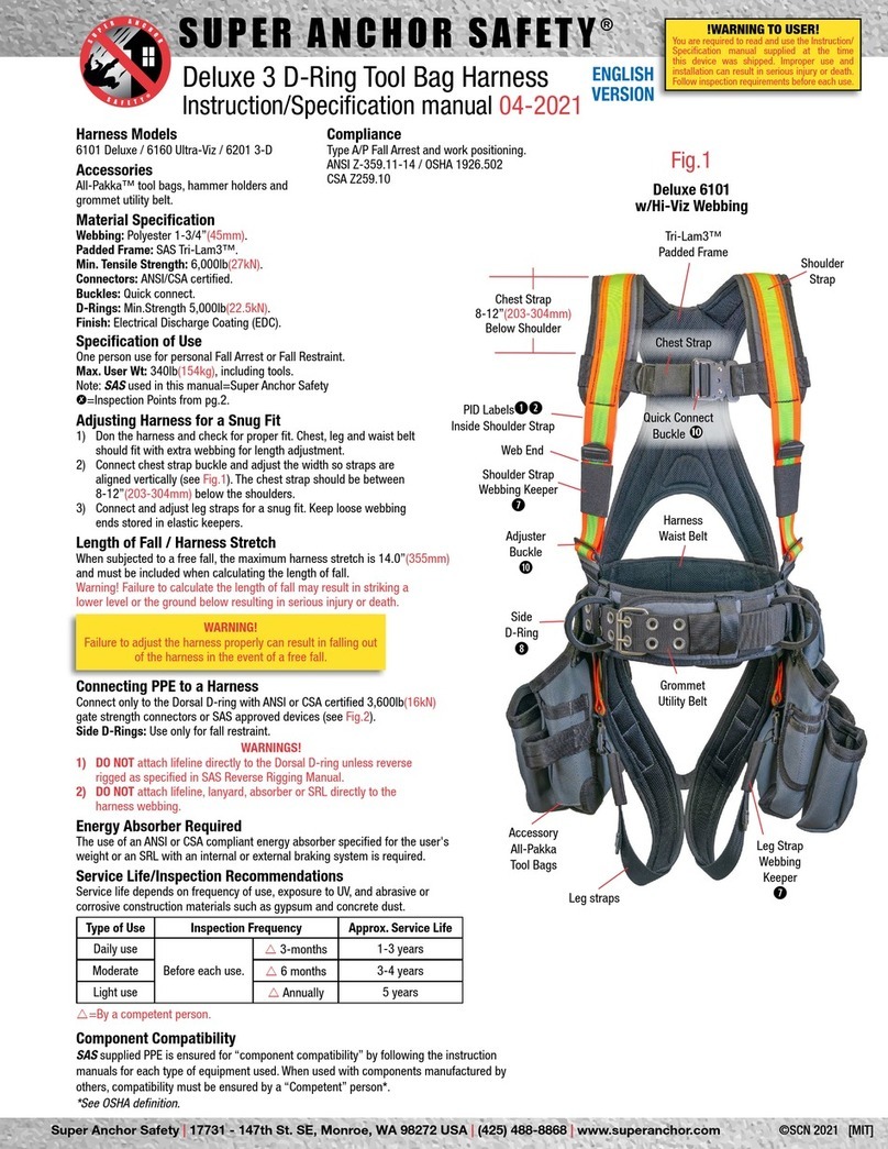
Super Anchor Safety SideWinder 2901k User manual

Super Anchor Safety |17731 - 147th St. SE, Monroe, WA 98272 USA |(425) 488-8868 |www.superanchor.com
SUPER ANCHOR SAFETY®
SideWinder™ Self Retracting Lifline (SRL)
Instruction/Specification Manual 2020
User Specifications
Max. User wt.: 130-310lb(59-140kg)
Max. Arrest Distance: 54”(1.37m)
Max. Free Fall: 24”(610mm)
Performance Specifications
Avg. Arrest force: 1,350lb(6kN)
Max. Arrest force: 1,800lb(8kN)
Brake System: Centrifugal
ENGLISH
VERSION
©SCN 2020 [MIT]
Compliance
ANSI Z359.12-2012 Type B
OSHA 1926.502
Part No. Length Wt.
2901k 50ft 18lb
2903k 30ft 16lb
2904k 20ft 14lb
2906k 10ft 12lb
!HAZARD WARNINGS!
• Cable must not come in contact with sharp or
abrasive surfaces, chemicals or acids.
• DO NOT wrap the cable around any object.
• DO NOT expose to high heat, open flame, cutting
or grinding tools, or electrical sources.
PPE Connection/Requirement
All PPE must comply with current ANSI, CSA or OSHA fall protection
standards and be inspected annually by a “competent” person.
Fall Arrest: Connect SRL cable “B” end ONLY to the dorsal D-ring
of a full body harness (FBH) as shown at Fig. 1.
DO NOT connect to side D-rings.
Fall Restraint: Connect SRL cable “B” end to the FBH dorsal
D-ring or side D-rings. See Fig.11b.
SRL Anchorage Point
Anchorage points that are not pre-engineered by SAS must be
engineered by a “competent” or qualified person and designed to
support the intended fall protection load.
Fall Arrest: Attach the “A” end to an anchorage point capable of
supporting 5,000lb(22.5kN) or 2x the engineered fall protection load.
See Fig.9a.
Fall Restraint: No free fall hazard exposure. The anchorage point
must be capable of supporting 3,000lb(13.6kN) or 2x the engineered
fall protection load. See Fig.11b.
Leading Edge/Low Slope Fall Hazards
Horizontal tie-off points as shown at Fig.11a increase the free fall
hazard to more than 24” due to the dorsal D-ring height above
the work surface. When exposed to a free fall of more than 24”, a
personal energy absorber is required to guard against severing the
wire cable during a fall. ANSI Z359.14-14 requires to use SRL-LE
models when the tie-off point is between horizontal and overhead
and leading edge fall hazards are present.
Service Life
The service life depends on the frequency of use, exposure to salt air
and moisture, and if the unit is used indoors or outdoors. In extreme
cases of contamination exposure, the SRL may require factory service
during the first year of use. See Table 1.0.
Factory Service: SRLs subjected to a free fall, do not pass function
tests or inspections, are required to be returned to SAS factory for
service or repair.
WARNING! DO NOT attempt to open the casing or make repairs. SRLs
have an interior recoil spring that is capable of causing serious injury.
Table 1.0 Service Life and Inspections
Note that all annual (12 months) or semi-annual (6 months) inspections must
be performed by a “competent” person before being returned to service.
Type of Use Approx.
Service Life Inspections
Indoor/Light 3-5 years Before each use
and every 12 months
Indoor/Heavy 2 years +
Outdoor/Heavy 1-2 years Before each use
and every 6 months
Salt Air 1 year
Note: Exposure to salt air, water saturation, gypsum and dust
will reduce the service life.
Storage
Store indoors in a dry area and hang from the “A” end to allow
moisture to drain. Do not place any objects on top of the casing to
prevent casing damage.
Disposal of SRL/Hazard Warning
Units removed from service must be disposed of in a way that prevents further use and
prevents the possibility of someone dismantling the SRL. Due to the acute danger posed
by the recoil spring, it is recommended to return non-serviceable units to the SAS factory
for safe disposal.
Fig.1
Fig.2
Model 2901k
Overhead Anchorage
Tie-Off Strap
w/D-ring
Carabiner
Casing
“A” end
Wire Cable
Dorsal
D-ring
Tongue Buckle
Full Body Harness
w/Side D-rings
Model TB-6067
4”
Steel Auto-Lock
Carabiner
No. 5001Z
Casing Handle
Steel Edge
cable severing
hazard.
Auxiliary
Label
Pack
Inspection
Label
Cable Grip
Swage Thimble
Fall Indicator
Swivel Snaphook
“B” end
Inspection Points pg. 2
Function
This device has a centrifugal
braking system that will lock up
when the cable is subjected to a
rapid movement. Release tension
on the cable to unlock.
!WARNING TO USER!
You are required to read and use the Instruction/
Specification manual supplied at the time
this device was shipped. Improper use and
installation can result in serious injury or death.
Follow inspection requirements before each use.
Warning
Label
Casing
Screws
Length
2901k 24”
2903k
2904k 21”
2901k

SUPER ANCHOR SAFETY®Page 2
SideWinder Manual 2020 English Version
Fig.2a Snaphook
Fig.3a
Fig.2b
Fig.3b
Fig.2c
Fig.3c
Push
gate
only
Gate Locked
Un-lock gate
Gate
Push
Push
Gate-
lock
Rivets
Release!
Gate closes
Gate open
Gate open
Pull gate
Barrel-lock
Gate
Rotate
Barrel-lock
Then release!
Gate closes
Push
Daily and Semi-Annual Inspections
Perform inspection/function tests for SRLs and connectors prior to each use. SRLs
should be inspected by a qualified or “competent” person every 6 months and
recorded on the SRL inspection label. A record of inspections, repair and removal
of equipment from service should be maintained for each SRL. The following
inspection points are a guideline of common conditions that occur as a result of
abuse, poor maintenance or long service life. Safety personnel are responsible for
drafting their own fall protection equipment inspection and maintenance program
which may include the information contained in this manual.
Remove equipment from service if any of the following
conditions are present:
Primary Inspection Points
Subjected to a free fall or other
force.
Obvious damage to any
component.
Has not been inspected annually.
Fails to pass inspection/function
tests.
PID labels unreadable or missing.
Service life is more than 5 years.
T=Remove From Service
Wire Cable is cut, abraded or knotted.
Swage or swage thimble is damaged
or missing. TFig.5, 7
Snaphook fall indicator is visible. T
Fig.8b
Casing is cracked, broken or seams
are separated. TFig.6
Casing handle is broken or bent.
TFig.1
Casing Screws are missing. TFig.6
Cable Grip is missing. TFig.5
Snaphook and/or Carabiner T
won’t pass inspection or function
tests.
Connectors:
Obvious damaged/missing rivets. T
Gate is bent or won’t close. T
Gate locking device is damaged. T
Gate in closed position, does not
lock. T
Table 2.0 Remove from service if any test fails.
Fig. Test Type Function Pass RFail. T
2a-3a Gate-lock Push against gate only Won't open Opens.
2b Gate-open Push gate-lock and gate Opens Won't open.
2c Gate-close Release gate and gate
Lock at same time
Snaps
shut
Won't close
and lock.
3b-3c Unlock gate Rotate barrel lock Gate opens Won’t open.
3a Gate closes Release gate/barrel Snaps shut Won't close.
Table 2.1 SRL Inspection/Lock Function Tests
Failure to pass any of these tests require the unit to be removed from service.
Test Type Test Specification Pass Fail
Deployment Pull out a few feet of cable
slowly and then retract slowly.
Smooth function,
no jerks or stops.
Cable won’t deploy.
Cable won’t retract.
Brake
See Fig.4
Secure “A” end from movement.
Pull quickly on “B” end. Perform
this test 3 times.
Cable locks up
and holds
position.
Cable does not
lock up.
Cable Pull out entire length of cable.
Hold in place with light pressure
vice grip as shown at Fig.5.
No evidence of
cuts, abrasions
kinks or knots.
Cable damage
present.
Fig.4
Cable Deployment
Brake Lock Test
Lock Test
Pull quickly
away from
casing.
Ü
Cable
Grip
Swages
Eye
Thimble
Seam
Casing
Screws
Fig.7
Cable Damage
Kink, Bend,
Gouge, or
Cut Strands
Extend the SRL Service Life
• DO NOT allow the cable to retract freely.
Uncontrolled cable recoil can damage the braking system and recoil
spring, causing irreparable damage.
• Salt Air or Chemical Exposure
Chemicals, salt air, gypsum, asphalt and earth dust produce oxidation
and can cause interior contamination of the braking system.
• Moisture Exposure
SRL casings are not air or water-tight. Units exposed to moisture or
water saturation should be stored in a vertical position in a dry area.
DO NOT store outside where salt air or moisture are present.
Fall Indicator Inspection
Fall indicators located below the Snaphook swivel will show a RED color
when subjected to a force of approx. 400lb. Remove SRL immediately
from service.
Auto-Lock Carabiner
Fig.8a
Fall indicator not visible.
Snaphook
swivel
Fig.8b
Fall indicator deployed.
Red band is visible.
Remove From Service!
Fig.5
Cable/Swage Inspection
Clamp or anchor the casing
and cable ends to prevent
recoil during inspection.
Fig.6
Casing Inspection
Examine all casing
seams for defects.
Move cable
grip to
inspect
swages.

SUPER ANCHOR SAFETY®Page 3English Version
Anchorage Point
SRLs are designed for use where the tie-off point is located overhead for fall arrest, but may
be used for fall restraint as shown on page 4. Swing-falls present the greatest hazard and
will increase in severity as a worker travels away from the tie-off point as shown at Fig.10a.
A fall protection plan that is specific to each job site should be provided by a “competent” or
qualified person. The sample plans shown here are for reference only.
Calculating the Length of Fall (LOF)
The LOF is a factor used to determine the ground clearance (GC) between the work surface
and the nearest lower level or an obstacle in the path of the swing-fall as shown at Fig.10b.
Sample Plan “A” LOF Standard Anchorage Attachment
Fig.9a is an example of standard overhead SRL attachment. To avoid swing-falls, travel along
the work surface fall hazard as shown here should be no more than a few feet from the
anchors vertical center point above. A pre-planned SRL service zone can be used to define
the area of protection provided by the tie-off point.
Note: Length of Fall (LOF) is a formula based on the maximum deployment lengths of the PPE
components and other factors and is used to estimate the ground clearance (GC).
Real life free falls may be greater or lesser due to unforeseen variables in the factors.
Table 3.0 Plan “A” LOF Calculation
• SL=31” The Service Length is the SRL component length +
the amount of the deployed SRL webbing.
• SRB=12” SRB is the amount of cable that is deployed
before the brake lock engages.
• HS=12” Full Body Harness stretch.
• EA=54” Energy Absorber deployment length.
Max. user wt. 310lb/Max. Free Fall 2ft.
• DR= 60” D-ring height above the work surface.
Total LOF=169” Length from Tie-Off point to the next lowest level
below the work surface.
Deduct TO=[84”] Tie-Off point height above the work surface.
Total=85” Min. Ground Clearance(GC) required.
WARNING: PROMPT RESCUE!
A plan for immediate rescue is necessary to avoid serious injury,
excruciating pain or death resulting from suspension trauma.
Use SAS S.T.E.P. 6060 suspension ladder and provide
user training in its use for each worker.
WARNING!
Insufficient
Ground Clearance!
A failure to
calculate the LOF
and connect PPE
correctly, can
result in striking
the ground or a
lower level in the
event of a fall and
may cause serious
injury or death.
SRL Internal Energy Absorber (EA)
The SRL’s cable brake lock system has an internal energy
absorbing design that limits the maximum arrest force to 1,800lb
or less when subjected to a free fall of no more than 24” with a
max. user wt. of 310lb.
Sample Plan “B” Swing Fall Hazard Warning!
Fig.10a is an example of an extreme swing fall hazard that results
from moving more than a few feet from the anchorage point above
when exposed to a fall hazard at the work surface edge. Swing
falls must be avoided to prevent serious injury.
Table 3.1 Plan “B” LOF Calculation
• SL=60” The Service Length is the SRL component
length + the amount of the deployed SRL
cable.
• SRB=12” SRB is the amount of cable that is deployed
before the brake lock engages.
• HS= 12” Full Body Harness stretch.
• EA= 54” Energy Absorber deployment length.
Max. user wt. 310lb/Max. Free Fall 2ft.
• DR= 60” D-ring height above the work surface.
Total LOF=198” Length from Tie-Off point to the next lowest
level below the work surface.
Deduct TO= [75”] Tie-Off point height above the work
surface.
Total = 123” Min. Ground Clearance(GC) required.
Work Surface
Service Length 31”
Distance
from
anchorage
point.
16”
Fig.10a
Swing-fall path
Tie-Off point
above work
surface.
(TO)
75”
Work Surface
Tie-Off point
above work
surface.
(TO)
84”
Fig.9a
Service
Length
(SL)
31”
Brake Lock Length
(SRB)
12”
Harness Stretch
(HS)
12”
Free Fall
Energy Absorber
Deployment
(EA)
54”
Fig.9b
D-Ring
Height
(DR)
60”
LOF
Length of Fall
169”
Distance from
work surface
to lower level=
Ground Clearance.
(GC)
85”=7ft-1”
Service
Length
(SL)
60”
Brake Lock Length
(SRB)
12”
Harness Stretch
(HS)
12”
Free Fall
Energy Absorber
Deployment
(EA)
54”
D-Ring
Height
(DR)
60”
Fig.10b
Distance from
work surface
to lower level=
Ground Clearance.
(GC)
123”=10ft3”
Distance from anchorage
point 60”
Service Length 60”
LOF
Length of
Fall
198”
SideWinder Manual 2020

24”
Above
Tie-Off
Point.
36”
Tie-Off
Point
SUPER ANCHOR SAFETY®Page 4English Version
Inspection Record
Record annual and
semi-annual inspections
and date of first use.
No. 6180-LE Energy Absorber (EA)
SRL “B” end Snaphook
Work Surface
Fall Hazard Edge
60”
D-ring
Height
Above
Work
Surface.
Leading Edge
Length of Fall
Sample Plan
(LOF)
18”
Harness and
components
stretch
60”
Max F
ree Fall
54”
Max. SRL-LE
Deployment
Length
60”
Foot to
D-ring
Length
LOF
192”
16ft
To ground or
next lower level
below work
surface.
SAS Factory Service
SRLs requiring warranty or service work must be returned to the SAS factory.
Contact the sales office to request a Return Authorization Form (RAF).
Offsite annual and semi-annual inspections that do not require service or
repair may be performed by a “Competent” person using SAS inspection
forms. Replacement PID labels will be provided if the original label data is
available.
Casing Warning Label
Do not attempt to repair an SRL. There is an interior recoil spring
that poses a serious safety hazard.
Fig.11b
Dorsal D-ring
24”
Side
D-ring
Fall Hazard
Fall Restraint Use
SRLs may be used for fall restraint when there is
no exposure to a free fall as shown in Fig. 11b. The
worker is prevented from moving close to the fall
hazard by a warning line or other guarding system.
The SRL connector “B” end may be attached to the
dorsal D-ring or side D-ring. Note: SRLs are not rated
for “work positioning” because the cable cannot be
set to a fixed length.
Fall Restraint Definition OSHA 1926.751
“A means of fall protection that prevents the user
from falling any distance.”
WARNING! Free falls over the edge of a fall hazard
can result in severing of the SRL cable. Safety
standards specify the use of an SRL with an external
E/A to prevent cable damage. Most deaths occur
from falls less than 8ft from the work surface.
Casing Marks
SRL model, cable length, serial no. and DOM ( date
of mfg.) are engraved at the time of shipping from
SAS factory.
Free Fall Hazard Warning
The following instructions apply only when a worker is exposed to a free fall hazard of more than 2ft.
Calculating the Free Fall Length:
The height of an SRL connection to the dorsal D-ring above the work surface determines the free fall length. As
shown at Fig.11b, the D-ring height above the work surface is 24”, the maximum free fall allowed Class A SRL’s.
Leading Edge (LE) Models Length of Fall
Shown at Fig.11a, the worker’s D-ring height is 5ft/60”above the work
surface the maximum free fall distance allowed for an LE model. The
maximum deployment length of the SRL internal braking system
combined with the external energy absorber
No. 6180-LE is 54”. The min. ground clearance is 16ft.
Fig.11a
SideWinder Manual 2020
Template SRL 3.0
SRL Label EE.1
©SCN 02-2020
[MIT]
!WARNING TO USER!
You are required to read
and use the Instruction/
Specification manual supplied
at the time this device was
shipped. Improper use and
installation can result in
serious injury or death. Follow
inspection requirements
before each use.
BEFORE EACH USE:
Perform locking and retraction
tests as specified in the
manual.
Mfg. Super Anchor Safety
Monroe, WA USA 98272
425-488-8868
Template SRL 3.1
SRL Label EE.2
©SCN 02-2020 [MIT]
BEFORE EACH USE:
Inspect and remove from
service if any of the following
conditions are present:
• Fall indicator on snaphook
swivel has been deployed.
• Cable has kinks, cuts or burs.
Storage, Maintenance, Use:
• Cable angle should not
exceed 40° from anchorage
point. See manual.
• Do not allow cable to retract
without tension serious
damage will result.
• Clean cable before storing.
• Store wet units vertically and
in a warm
Maintenance WARNING!
Do open the casing or attempt
repair. This device has an Internal
spring that can seriously injure a
person. Return to SAS factory for
service or repair
Template SRL 3.1
SRL Label EE.3
©SCN 02-2020 [MIT]
Compliance
ANSI Z359.14-2014 TYPE B
Cable: Galvanized steel
3/16”(4.8mm)d.
min.strength: 4,000lb(18kN)
Avg. Arrest force 900lb(4kN)
Max. Arrest distance: 42”(1.06m)
1-Person max wt: 310lb(140kg)
Including tools and equipment
Max. Free fall length: 54”(1.4m)
Temperature range-22°F(-30°C)
122°F (50°C)
! HAZARDS !
• DO NOT allow cable to come in
contact or wrap around sharp
or abrasive surfaces, equipment
tools or electrical sources.
• Do not use for fall restraint or
work positioning.
• Calcuate free fall length from
all leading edges.
Template SRL 3.0
SRL Label EE.1S
©SCN 02-2020
[MIT]
¡ADVERTENCIA AL USUARIO!
Se requiere leer y utilizar
el manual de Instrucción/
Especificación proveído en
el momento de envío de este
dispositivo. El uso e instalación
inadecuados puede resultar en
lesiones graves o la muerte.
Seguir los requisitos de
inspección antes de cada uso.
ANTES DE CADA USO:
• Efectuar las pruebas de
bloqueo y retracción cómo se
especifica en el manual.
Inspeccionar y sacar de servicio
si cualquiera d las siguientes
condiciones se presentan:
• El indicador de caída en
el rotador del gancho de
seguridad se ha desplegado.
• El cable tiene retorceduras,
cortadas o rebabas.
Template SRL 3.1
SRL Label Indicator
©SCN 02-2020 [MIT]
Fall Indicator is visible
Remove From Service!
Red Fall Indicator
Indicador de caída de
color rojo
El indicador de caída
esta visible.
Retirarlo de servicio
Template SRL 3.1
SRL Label EE.2S
©SCN 02-2020 [MIT]
Almacenamiento,
Mantenimiento, Uso:
• El ángulo del cable no debe
exceder 40° del punto de
anclaje. Ver el manual.
• No permitir que el cable se
retracte sin tensión resultara
en danos serios.
• Limpiar el cable antes de
almacenar.
• Almacenar unidades mojadas
verticalmente y en un área
tibia si han sido expuestas al
agua helada.
• Rango de Temperatura
-22°F(-30°C) 122°F (50°C)
¡ADVERTENCIA de Mantenimiento!
No abrir el revestimiento e intentar
reparar. Este dispositivo tiene un
resorte interno que puede lastimar
a una persona gravemente.
Regresarlo a la fábrica SAS para
servicio de reparacion.
Year: Month: By: Pass
Inspection Record
Date of First Use:
____________________
Property of: ______________
________________________
Template SRL 3.1
SRL Matrix
©SCN 02-2020 [MIT]
Template SRL 3.1
SRL Label EE.3S
©SCN 02-2020 [MIT]
Cable: Acero Galvanizado
3/16”(4.8mm)d.
Fuerza Mínima: 4,000lb(18kN)
Fuerza de Detención Promedio
900lb(4kN)
Distancia de Detención Máxima:
42”(1.06m)
1-Persona Peso Maximo:
310lb(140kg)
Incluyendo Equipo y Herramienta
Longitud de Caída Libre Máxima:
54”(1.4m)
¡PELIGROS!
• NO permitir que el cable tenga
contacto o se envuelva alrededor
de superficies afilados o abrasivos,
herramientas del equipo o fuentes
de electricidad.
• No utilizar para restricción de caída
o posicionamiento de trabajo.
• Calcular la longitud de la caída libre
de todos los bordes delanteros.
• Evitar peligros de caídas colgantes y
• Se requiere AMORTIGUADOR para
uso con este dispositivo.
SRL Label W.1.1S Eng-SP © SCN 03-2020 [MIT] Template SRL W.1
WARNING! Do not disassemble the casing. Return to
SAS factory for service or repair. Recoil spring inside is
extremely dangerous and can result in serious injury or death.
¡ADVERTENCIA! No desarmar oi retirar las tapas de un SRL. Para
reparaciones o servicio de mantenimiento, devolver la unidad a las
instalaciones de SAS. El resorte de retracción dentro de la unidad, es
extremadamente peligroso y podría ocasionar heridas serias o la muerte.
PID Labels
English and Spanish PID labels are attached to the SRL casing as
shown at Fig.2. Request replacement labels from SAS factory.
English Label Pack EE Spanish Label Pack EE.S
Model Length
Serial No. DOM
This manual suits for next models
3
Other Super Anchor Safety Safety Equipment manuals

Super Anchor Safety
Super Anchor Safety Deluxe 3 D-Ring User manual

Super Anchor Safety
Super Anchor Safety WS-TrussBar User manual

Super Anchor Safety
Super Anchor Safety ARS Series User manual

Super Anchor Safety
Super Anchor Safety PD-6101 User manual

Super Anchor Safety
Super Anchor Safety Version 07 SCN User manual

Super Anchor Safety
Super Anchor Safety 6060 User manual

Super Anchor Safety
Super Anchor Safety Quick-Strap User manual