Surface Concept CEM 4230 User manual

CEM 4230 Detector Setup Manual
CEM 4230 Detector Setup
Manual

2
Surface Concept GmbH
Am Sägewerk 23a
55124 Mainz
Germany
phone: +49 6131 62716 0
fax: +49 6131 62716 29
email: info@surface-concept.de
web: www.surface-concept.de
All rights reserved. No part of this manual may
be reproduced without the prior permission
of Surface Concept GmbH.
CEM 4230 Detector Setup
Manual Version 2.0
Printed on 2018-09-14

3
CEM 4230 Detector Setup Manual
1 Table of Contents
1 Table of Contents ......................................................................................................................3
2 Introduction................................................................................................................................4
2.1 General Information..........................................................................................................4
2.2 Safety Instructions .............................................................................................................4
3 Installation...................................................................................................................................5
3.1 Initial Inspection.................................................................................................................5
3.2 Installation ............................................................................................................................5
3.2.1 Mounting the CEM..................................................................................................5
3.2.2 Cabling and High Voltage ....................................................................................7
4 Operation of the CEM..............................................................................................................9
4.1 “Start Up“ Procedure for First Time Operation.........................................................9
4.1.1 Basic Checks ..............................................................................................................9
4.2 Standard Operating Procedure.................................................................................. 10
4.3 Bake Out Procedure.......................................................................................................11
5 Additional Information........................................................................................................12
5.1 Storage................................................................................................................................12
5.2 Replacement.....................................................................................................................12
6 List of Figures ..........................................................................................................................13

4
2 Introduction
2.1 General Information
This manual is intended to assist users in the installation, operation and maintenance of Release Version
1.1 of the CEM 4230 Megaspiraltron Detector Setup.
2.2 Safety Instructions
Pleaseread thismanualcarefullybeforeperforminganyelectrical orelectronicoperations
and strictly follow the safety rules given within this manual.
The following symbols appear throughout the manual:
Note
The“note symbol”marks text passages, which contain important information/hints about
the operation of the detector. Follow this information to ensure a proper functioning of
the detector.
The “caution symbol” marks warnings, which are given to prevent an accidentally
damaging of the detector or the readout system. Do NOT ignore these warnings and
follow them strictly. Disregarding these warnings my cause permanent damage to the
system and is not covered by the device warranty.
The “high voltage symbol” marks warnings, given in conjunction with the description of
the operation/use of high voltage supplies and/or high voltage conducting parts.
Hazardous voltages are present, which can cause serious or fatal injuries. Therefore
only persons with the appropriate training are allowed to carry out the installation,
adjustment and repair work.

5
CEM 4230 Detector Setup Manual
3 Installation
3.1 Initial Inspection
Table 1: Packing list for the CEM 4230 Detector Setup.
Visual inspection of the system is required to ensure that no damage has occurred during shipping. Should
there be any signs of damage, please contact SURFACE CONCEPT immediately. Please check the delivery
according to the packing list (see Table 1) for completeness.
• CEM 4230 Detector Setup in transport container (delivered under Argon atmosphere)
3.2 Installation
3.2.1 Mounting the CEM
The CEM is mounted to a transport container which is lled with Argon atmosphere. To install the CEM into
your vacuum chamber, proceed as follows:
Figure 1: A CEM assembly mounted to the transport container and after removal.

6
• Open the plastic bag containing the transport container.1x Wall Power Supply (5V/3A)
• Remove the three pairs of nuts and screws holding the CEM.
• Carefully remove the CEM assembly by pulling the ange upwards. The cables and the CEM mount
may touch the opening, but do not rotate the assembly before the CEM funnel has fully cleared the
opening.
• Remove the viton gasket. Again, touching the cables or CEM mount with the gasket is not a problem,
but keep away from the CEM funnel.
The funnel at the front of the CEM should be protected from exposure to particle
contamination. While transporting the CEM outside the container keep the funnel
pointing downwards or inside a suitable container. Larger particles can be removed by
carefully using tweezers.
• Install the CEM by placing a copper gasket on the base ange and inserting the CEM assembly into an
appropriate DN40CF ange opening. Take care not to touch the walls or other obstacles with the CEM
funnel and do not pinch the cables between the ange edges.
• After installation of the CEM assembly, evacuate the chamber. This is a high-pressure channeltron, do
not perform bakeout.
• At this point, you can perform some basic resistance checks, see Chapter 4.1.
• Keep the transport container in case the CEM must be sent back for repair or modication. It can also
be used for storing the detector temporarily when not installed in a vacuum chamber.
Adry atmosphere/rough vacuumis recommendedin bothcases.SeeChapter5.1foradditionalinformation.
• High-Pressure channeltron assembly: Do not perform bakeout when using the
standard mount.
• Maximum operating temperature: 70 °C
• Maximum ambient pressure with high voltage applied: < 1E-3 mbar
Note
The CEMs should be kept under vacuum or in protective atmosphere if possible.
Alternatively use a dry atmosphere.Water contamination may change gain characteristics
over time. The best long term storage environment is an oil free vacuum in the 10E-2
mbar range or better. The transport container is not designed for a long term storage of
the CEMs.

7
CEM 4230 Detector Setup Manual
3.2.2 Cabling and High Voltage
The general connection scheme of the CEM 4230 Detector Setup including its CEM decouple box is shown
in Figure 2. The components shown greyed out are additional possibilities for further pulse processing.
Those devices are not part of the CEM 4230 Detector Setup.
Figure 2: Possible connection scheme of the CEM 4230 Detector Setup.
• Connect any HV Supply to the 3 SHV feedthroughs of the CEM base ange.
• Connect any HV Supply to the“U-DET” SHV connector of the decoupling box.
• In case of using a Surface Concept CEM Decoupling Box, mount the CEM Decoupling Box to the ange
of the CEM and connect the 3 SHV cables of the decoupling box to the 3 SHV feedthroughs of the CEM
ange.
• Terminate the“U-IN”SHV connector of the decoupling box with a SHV termination plug or by a dened
reference potential.
• “Pulse Out” is the signal output for the CEM pulses. The corresponding connector type is BNC with a 50
Ohm terminated signal line.

8
• Use any analogue pulse processing devices (e.g. the Surface Concept 1Channel Preamplier/ CFD) for
the processing of the analogue CFD pulses.
• Use any digital counter or time resolved measurement device (e.g. the Surface Concept 4 Channel
Counter or the Surface ConceptTime-to-Digital Converter) for pulse recognition/ counting and/ or time
resolved measurements.Connect any HV Supply to the 3 SHV feedthroughs of the CEM base ange.
Finish the complete cabling before any HV supplies and/ or pulse processing devices are
turned on and any software is started. Also, close the software and turn o any connected
devices, especially any high voltage before performing any changes to the cabling.
Don’t start the detector operation as long as you are not familiar with the detailed
descriptions of Chapter 4 within this manual.

9
CEM 4230 Detector Setup Manual
4.1 “Start Up“ Procedure for First Time Operation
4 Operation of the CEM
Note
Mistakes, which lead to wrong measurement results or damage the CEM can happen very
easily while taking the system into operation. Therefore it is strongly advised to read the
following sections completely beforehand and to strictly follow all advices given.
Due to gain degradation it will become necessary to increase the operating voltage from
time to time.
4.1.1 Basic Checks
We recommend this procedure when taking the system into operation the rst time and after every
venting.
• Remove any cables/plugs from the feedthrough ange if connected.
• Use a multimeter to check the resistance between each of the three HV inputs “U-IN”, “U-OUT” and
“U-DET”on the CEM assembly and between any of the three inputs“U-IN”,“U-OUT”, U-DET”and ground.
The only measurable resistance should be between R(U-IN/U-OUT) of several 10 MOhm, of R(U-IN/U-
DET) of several 10 MOhm and of R(U-OUT/ R-DET) of 1 MOhm. All resistances towards ground should
be innite (> 2 GOhm).
• Reconnect the cabling and nish it as described in chapter 3, if not already done.
• Turn on the power for all devices.
Ion gauges and ion pump are both sources for electrons and ions. Ion pumps can also be
a source for X-rays. They can produce so many particles/X-rays that a CEM is in complete
overload, even when not facing the particle source directly. This will wear out the CEM
very fast. Turn o ion pumps and ion gauges before turning on the high voltage.
• Switch on any HV supply.
• If possible, watch the vacuum pressure while increasing the high voltage; turn the voltages back, if an
unusual increase is observed in the pressure (indicator for high voltage sparking).
• Increase the voltage step wise up with around 400 V per minute to the operation voltage of the CEM. It
is given in the specication sheet of the detector.

10
High voltage sparks may seriously damage the detector. Observe the chamber pressure
carefully every time the high voltage is turned on. Switch o the high voltage immediately
in case of a temporary pressure rise by an order of magnitude or more. This indicates
high voltage sparking.
If sparking occurs, turn down the high voltage immediately and wait some time (up to 5
min.). Check for shorts, start the“Start-Up”procedure again with and increase voltage in
small steps. Turn o the high voltage completely, stop the procedure and call SURFACE
CONCEPT for further assistance, if is it not possible to reach the operation voltage without
sparking.
• After nishing the previous steps with a satisfying result, you may now start carefully with a charged
particle or light source observing the detector output.
Turn o the high voltage, close the software and turn o the controller before performing
any changes of the cabling.
4.2 Standard Operating Procedure
Use this procedure later on for all operations when the detector has already been operated in vacuum
before and has not been vented in between.
• Connect the CEM 4230 Detector Setup as described in chapter 3.
• Be sure that the vacuum pressure at the detector is below the specied maximum operating pressure.
• Turn o all sources for electrons, ions, light or X-rays that might hit the detector.
• Turn on the power for all devices.
• Switch on any HV supply.
• If possible, watch the vacuum pressure while increasing the high voltage; turn the voltages back, if an
unusual increase is observed in the pressure (indicator for high voltage sparking).
• Increase the voltage step wise up in a couple of minutes to the operation voltage of the CEM. It is given
in the specication sheet of the detector.
• Switch on your charged particle or light source observing the detector output.
Turn o the high voltage, close the software and turn o the controller before performing
any changes of the cabling.

11
CEM 4230 Detector Setup Manual
4.3 Bake Out Procedure
This high-pressure channeltron assembly is not intended for bake-out.

12
5 Additional Information
5.1 Storage
CEMs are comparatively resistant to the repeated aeration of the vacuum chamber. However, when exposed
to air over a longer period of time, the binding of moisture leads to a decrease in gain and therefore to a
reduction of the lifetime.
For this reason, the CEM assemblies are delivered in a sealed container lled with argon. We recommend
not opening the container before the detector is actually required. Alternatively, store the CEMs in argon,
dry air or even better, in vacuum.
Water may lead to a reduction in the work function, resulting in a higher gain. During the burn-in after
having been stored for a longer period of time, the CEMs may pass through a deep valley of gain until
they reach a stable plateau again. This should be considered when setting the applied voltage and the
discriminator threshold.
5.2 Replacement
Note
Contact SURFACE CONCEPT before performing a replacement.
Please contact Surface Concept before performing replacement of any parts. We will provide you with a
detailed step by step description.

13
CEM 4230 Detector Setup Manual
6 List of Figures
Figure 1: A CEM assembly mounted to the transport container and after removal...................................................................................... 5
Figure 2: Possible connection scheme of the CEM 4230 Detector Setup........................................................................................................ . 7
Table of contents
Other Surface Concept Security Sensor manuals

Surface Concept
Surface Concept Delayline DLD 8080 User manual
Surface Concept
Surface Concept DLD4040 User manual
Surface Concept
Surface Concept HVPS User manual
Surface Concept
Surface Concept Delayline DLD 8080 User manual
Surface Concept
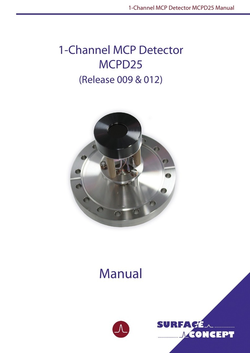
Surface Concept MCPD25 User manual
Surface Concept
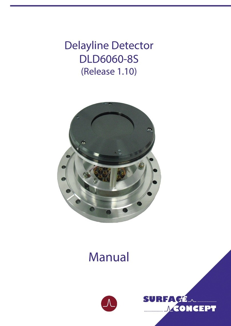
Surface Concept DLD6060-8S User manual
Surface Concept
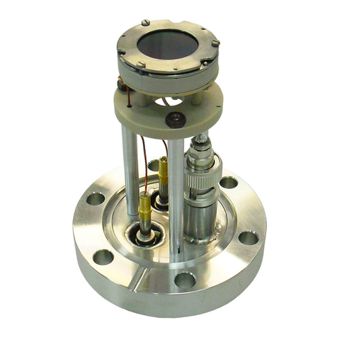
Surface Concept MCPD18 User manual
Surface Concept
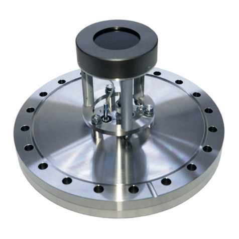
Surface Concept MCPD40 User manual
